EP1987907A2 - Reibrührschweißverfahren - Google Patents
Reibrührschweißverfahren Download PDFInfo
- Publication number
- EP1987907A2 EP1987907A2 EP08009241A EP08009241A EP1987907A2 EP 1987907 A2 EP1987907 A2 EP 1987907A2 EP 08009241 A EP08009241 A EP 08009241A EP 08009241 A EP08009241 A EP 08009241A EP 1987907 A2 EP1987907 A2 EP 1987907A2
- Authority
- EP
- European Patent Office
- Prior art keywords
- face
- plate
- friction stir
- joining
- raised
- Prior art date
- Legal status (The legal status is an assumption and is not a legal conclusion. Google has not performed a legal analysis and makes no representation as to the accuracy of the status listed.)
- Granted
Links
- 238000005304 joining Methods 0.000 title claims abstract description 86
- 238000003756 stirring Methods 0.000 title claims abstract description 67
- 238000000034 method Methods 0.000 title claims description 16
- 238000003466 welding Methods 0.000 claims description 19
- 238000004519 manufacturing process Methods 0.000 description 10
- 238000010276 construction Methods 0.000 description 5
- 229910052751 metal Inorganic materials 0.000 description 4
- 239000002184 metal Substances 0.000 description 4
- 238000003825 pressing Methods 0.000 description 4
- 239000000463 material Substances 0.000 description 3
- 229910000838 Al alloy Inorganic materials 0.000 description 2
- 238000003780 insertion Methods 0.000 description 1
- 230000037431 insertion Effects 0.000 description 1
Images

Classifications
-
- B—PERFORMING OPERATIONS; TRANSPORTING
- B23—MACHINE TOOLS; METAL-WORKING NOT OTHERWISE PROVIDED FOR
- B23K—SOLDERING OR UNSOLDERING; WELDING; CLADDING OR PLATING BY SOLDERING OR WELDING; CUTTING BY APPLYING HEAT LOCALLY, e.g. FLAME CUTTING; WORKING BY LASER BEAM
- B23K20/00—Non-electric welding by applying impact or other pressure, with or without the application of heat, e.g. cladding or plating
- B23K20/12—Non-electric welding by applying impact or other pressure, with or without the application of heat, e.g. cladding or plating the heat being generated by friction; Friction welding
- B23K20/122—Non-electric welding by applying impact or other pressure, with or without the application of heat, e.g. cladding or plating the heat being generated by friction; Friction welding using a non-consumable tool, e.g. friction stir welding
-
- B—PERFORMING OPERATIONS; TRANSPORTING
- B23—MACHINE TOOLS; METAL-WORKING NOT OTHERWISE PROVIDED FOR
- B23K—SOLDERING OR UNSOLDERING; WELDING; CLADDING OR PLATING BY SOLDERING OR WELDING; CUTTING BY APPLYING HEAT LOCALLY, e.g. FLAME CUTTING; WORKING BY LASER BEAM
- B23K33/00—Specially-profiled edge portions of workpieces for making soldering or welding connections; Filling the seams formed thereby
-
- B—PERFORMING OPERATIONS; TRANSPORTING
- B23—MACHINE TOOLS; METAL-WORKING NOT OTHERWISE PROVIDED FOR
- B23K—SOLDERING OR UNSOLDERING; WELDING; CLADDING OR PLATING BY SOLDERING OR WELDING; CUTTING BY APPLYING HEAT LOCALLY, e.g. FLAME CUTTING; WORKING BY LASER BEAM
- B23K2101/00—Articles made by soldering, welding or cutting
- B23K2101/04—Tubular or hollow articles
- B23K2101/045—Hollow panels
-
- Y—GENERAL TAGGING OF NEW TECHNOLOGICAL DEVELOPMENTS; GENERAL TAGGING OF CROSS-SECTIONAL TECHNOLOGIES SPANNING OVER SEVERAL SECTIONS OF THE IPC; TECHNICAL SUBJECTS COVERED BY FORMER USPC CROSS-REFERENCE ART COLLECTIONS [XRACs] AND DIGESTS
- Y10—TECHNICAL SUBJECTS COVERED BY FORMER USPC
- Y10T—TECHNICAL SUBJECTS COVERED BY FORMER US CLASSIFICATION
- Y10T428/00—Stock material or miscellaneous articles
- Y10T428/12—All metal or with adjacent metals
Definitions
- the present invention relates to a friction stir joining method.
- the present invention is suitable for a friction stir joining method of an aluminum alloy made extruded frame member which is used in a railway vehicle or a building structure etc.
- a friction stir joining method is a method in which by rotating a round rod (it is called as "a rotary tool") which is inserted into a joining portion and moving the rotary tool along to a joining line of extruded frame members, and the friction stir joining portion is heated, softened and plastically fluidized and a solid-stately joined.
- the rotary tool is comprised of a small diameter portion which is inserted into the friction stir joining portion and a large diameter portion which is positioned at an outside of the small diameter portion of the rotary tool.
- the small diameter portion and the large diameter portion of the rotary tool have the same axis. A boundary between the small diameter portion and the large diameter portion of the rotary tool is inserted a little into the joining portion.
- a joining of two faces of hollow extruded frame members is carried out from one of the two faces of the hollow extruded frame member. Namely, a plate of one side face is abutted and from another face side of the another member a friction stir joining is carried out. An outer face side of said plate is joined flatly. An end portion of the plate of the another face side is orthogonal to a thickness direction.
- step-wise difference it is necessary to make small the pitch of the pressing-under metal fixing means, then the apparatus becomes a high cost. Further, after the temporary fixing welding, when the friction stir joining is carried out, it is necessary to remove be the step-wise difference and similarly there is a problem. When the condition where there is the step-wise difference, after that it is impossible to remove the step-wise difference.
- an object of the present invention is that in the abut joining of the plates a joining in which a step-wise difference does not exist in a joining portion is carried out.
- the present invention provides a friction stir joining method comprising the steps of: inserting a raised portion of an end portion of a plate of a first frame member into a recessed portion of an end portion of a plate of a second frame member; and to the insertion-into portion inserting a rotary tool from one face side of the plate and carrying out flatly a friction stir joining to another face side of the plate.
- the present invention provides a manufacturing method of a structure body comprising the steps of: inserting a raised portion of an end portion of a plate of a first frame member into a recessed portion of an end portion of a plate of a second frame member; to the insertion-into portion inserting a rotary tool from one face side of the plate and carrying out flatly a friction stir joining to another face side of the plate; and positioning a face of the one side of a matter which has obtained by the friction stir joining to an outer face of a structure body and manufacturing the structure body.
- the present invention provides a manufacturing method of a car body comprising the steps of: inserting a raised portion of an end portion of a plate of a first frame member into a recessed portion of an end portion of a plate of a second frame member; to the insertion-into portion inserting a rotary tool from one face side of the plate and carrying out flatly a friction stir joining to another face side of the plate; and positioning a face of the one side of a matter which has obtained by the friction stir joining to an outer face of a car body and manufacturing the car body.
- the present invention provides a friction stir joining use frame member wherein, a recessed portion is provided at an end face of a rectangular direction against a thickness direction of a plate.
- the present invention provides a friction stir joining use frame member wherein, a raised portion is provided at an end face of a rectangular direction against a thickness direction of a plate.
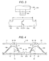
- Fig. 1 is an enlarged view showing an abutted portion of Fig. 4 .
- Fig. 2 is an enlarged view of the abutted portion shown in Fig. 1 and shows a view of a condition of the abutted portion before the abutting of the extruded frame members, and Fig. 3 shows a condition of after the abutting.
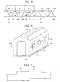
- Fig. 4 is an enlarged view of an essential portion of Fig. 5.
- Fig. 5 is a longitudinal cross-sectional view of a side structure body of Fig. 6 .
- a car body 200 is comprised of a side structure body 201 for constituting a side face of the car body 200, a roof structure body 202 for constituting a roof of the car body 200, a stand frame 203 for constituting a floor of the car body 200, and a side structure body 204 for constituting an longitudinal direction end portion of the car body 200.
- Each of the side structure body 201, the roof structure body 202, and the stand frame 203 is constituted respectively by joining plural extruded frame members.
- a longitudinal direction of the extruded frame member is formed toward a longitudinal direction of the car body 200.
- the extruded frame member is a hollow frame member made of an aluminum alloy.
- a constitution and a joining method of a hollow extruded frame member 10 and a hollow extruded frame member 20 for constituting the side structure body 201 will be explained.
- Other portions and other structure bodies are similar to the above.
- the hollow frame member 10 and the hollow extruded frame member 20 are comprised of two sheet face plates 11, 12 and 21, 22 and truss shape arranged plural ribs 13 and 23.
- the two sheet face plates 11 and 12 (the two sheet face plates 21 and 22) are substantially in parallel.
- a pitch of the truss structure according to ribs 13 and 23 is the same.
- the truss structure is constituted by the ribs 13 and 23 and a center line of a plate thickness of the face plates 11 and 12 and the face plates 21 and 22.
- An apex exists at a side of the face plates 11 and 12 and the face plates 21 and 22.
- rails 19 and 29 for installing machines and apparatuses are provided integrally.
- the rails 19 and 29 are comprised of L shape two members.
- the rails 19 and 20 are seats for installing the machines and apparatuses such as interior mounting plates and chairs, etc..
- End portions of the face plates 12 and 22 which are positioned an outer face side of the car body project to a side of the adjacent hollow frame members 20 and 10 from the end portions of the face plates 11 and 21 in the car body side. These projected face plates are indicated by 12b and 22b. By abutting end portions of the face plates 12b and 22b to each other, the friction stir joining is carried out. A plate thickness of each of the face plate 12b and 22b is thicker than another portion of the face plates 12 and 22.
- the hollow frame members 10 and 20 are mounted on a bed 240 by laying them the face plates 12 and 22 at the lower portion.
- the side of the face plate 11 and 231 are formed to the upper portion.
- a rotary tool 250 By inserting a rotary tool 250 to the abutted portion from the upper portion and the friction stir joining is carried out.
- the friction stir joining is carried out from the inner side of the car.
- raised portions 16 and 26 which project in the car inner side (namely, the face plates 11 and 21 side) are provided.
- a width and a height of each of the raised portions 16 and 26 are substantially the same.
- connection member 30 Between the end portion of the face plate 11 in the car inner side and the face plate 21 is joined with a connected through a connection member 30.
- a connection member 30 To the end portion of the connection member 30 is mounted (overlapped) to a seat 27 which is provided on the apex of the truss structure.
- a seat 17 To the end portion of the connection member 30 is mounted (overlapped) to a seat 17 which is provided on the apex of the truss structure..
- the seat 27 is arranged at an intersecting point between the rib 23A and the rib 23B.
- the seat 17 is arranged at an intersecting point between the rib 13A and the rib 13B. At a center of the width of the seat 27 the above stated intersecting point is arranged..
- the above stated intersecting point is arranged. Namely, the apex of the truss of the end portion is arranged at the central portion of the width of the seat 27 and the apex of the truss of the end portion is arranged at the central portion of the width of the seat 17.
- the width of the seat 27 is similar to the width of the raise portion 35 of the connection member 30 and the width of the seat 17 is similar to the width of the raise portion 35 of the connection member 30.
- the seat 27 is recessed from the outer face of the face plate 21 and the seat 17 is recessed from the outer face of the face plate 11.
- the end portion 27b of the face plate 21 is inclined as a groove for the arc welding to the connection member 30 and the end portion 17b of the face plate 11 is inclined as a groove for the arc welding to the connection member 30.
- connection member 30 is arranged to aim to form the surfaces of the plate plates 11 and 21 being continuously just as. For this reason, the seat 27 (17) is recessed with a plate thickness of the face plate 21 (11) _against the outer face of the face plate 21 (11).
- the central portion except for the both end portions of the connection member 30 is a plate 31 and a plate thickness of the plate is substantially same to the plate thickness of the face plate 21 (11).
- the raised portions 35 which project to an upper portion is provided at the both ends of the connection member 30.
- An upper face of the raised portion a V-shape groove 36 is provided.
- the groove 36 is arranged at a center of the width of the raised portion 35.
- a width of the raised portion 35 is larger than a diameter of a large diameter portion 252 of the rotary tool 250.
- the groove 36 becomes a subject matter for position detecting to lead the rotary tool 250.
- the groove 36 is detected by a laser sensor and the axial center of the rotary tool 250 is coincided with the groove 36.
- An extension line of the groove 36 namely on the axial center of the rotary tool 250, there is an intersecting point of the two rib 13A (23A) and rib 13B (23B).
- connection member 30 is smaller than an interval of the face plates 11 and 21 of the two hollow frame members 10 and 20.
- the connection member 30 is made of the extruded frame member having the same material of the hollow frame members 10 and 20.
- a length of the connection member 30 is the same of the length of the hollow frame members 10 and 20.
- a distance P from the end portion of the face plate 11 to the end portion of the face plate 21 is the same pitch P of the truss structure of the other positions.
- the truss structure of the hollow frame member is an isosceles triangle.
- the truss structure of the end portion of the hollow frame members 10 and 20 is not an isosceles triangle.
- the rib 13A (23A) is connected to a midway of the face plate 12 (22) and the rib 23B is connected to a midway of the face plate 22.
- a space for inserting the friction stir joining apparatus is formed between a connection portion between the rib 13A and the face plate 12 and a connection portion between the rib 23A and the face plate 22, a space for inserting the friction stir joining apparatus is formed.
- the plate thickness of the ribs 13A and 23A are thicker than the plate thickness of the ribs 13B and 23B.
- the plate thickness of the ribs 13B and 23B are thicker than the plate thickness of other ribs 13.
- the connection portions between the ribs 13A, 13B and 13 and the face plates 11 and 12, 21 and 22 have an arc shape. Further, the thickness of the connection member 30 is determined according to the strength aspect.
- the end portion of the face plates 12b and 22b namely a construction of the abutted portion will be explained.
- a trapezoid shape raised portion 22c which projects in the face plate 22b side is provided.
- a trapezoid shape recessed portion 12c is provided, this recessed portion 12c receives the raised portion 22c of the face plate 22b.
- the end faces 12d and 22d of the face plates 12b and 22b can be contacted.
- the end faces 12d and 22d of the face plates 12b and 22b, except for the recessed portion 12c and the raised portion 22c, are substantially orthogonal in the thickens directions of the face plates 12b and 22b.
- a height and a width of the recessed portion 12c are larger a height and a depth of the raised portion 22c.
- the upper end portions of the recessed portion 12c and the raised portion 22c are formed at an upper portion of an extension line of the upper faces (the inner face of the car body) 12bb and 22bb of the face plates 12b and 22b. Namely, the upper end portions of the recessed portion 12c and the raised portion 22c are existed in the raised portions 16 and 26.
- the recessed portion 12c and the raised portion 22c are arranged to the end portion of a rectangular direction against the thickness direction of the face plates 12b and 22b.
- the manufacturing method of this structure body will be explained.
- the hollow frame members 10 and 20 are mounted on and fixed to the bed 40.
- the face plates 12b and 22b are abutted, and the raised portion 22c of the end portion of the face plate 22b is inserted into the recessed portion 12c of the face plate 12b.
- the lower faces (the outer face of the car body) of the face plates 12b and 22b becomes substantially the same face.
- the raised portion 22c is inserted into the recessed portion 12c.
- the hollow frame member has a wave form in an upper and lower direction, after the abutting the frame member will maintain the wave form or the substantially linear form.
- the outer faces of the face plates 12b and 22b become substantially the same face.
- the end faces 12d and 22d contact with or approach.
- An upper face of the bed 40 on which the abutted portion of the face plates 12b and 22b are mounted is flat.
- Three portions which are the vicinity of the abutted portion of the face plates 12b and 22b, a cross-point vicinity of the ribs 13A and 23A, the face plates 12b and 22b, and a cross-point vicinity of the ribs 13B and 23B and the face plates 12 and 22 are mounted on the bed 40 having the same height.
- the rotary tool 250 of the friction stir joining apparatus is inserted from the upper portion to the abutted portion of the raised portions 16 and 26 and is moved along to a joining line and then the friction stir joining is carried out.
- the axial center of the rotary tool 250 is a perpendicular direction (the direction along to the normal line of the joining portion). However, against an advancing direction of the rotary tool 250 the axial center is inclined as already known.
- the rotary tool 250 comprises the large diameter portion 252 and the small diameter portion 251 at a tip end of the large diameter portion 252.
- the tip end of the lower end of the small diameter portion 251 of the rotary tool 250 is positioned at a lower face from an upper face of the face plates 12b and 22b.
- a lower end of the large diameter portion 252 of the rotary tool 250 is positioned from the lower end of the recessed portion 12c.
- the lower end of the large diameter portion 252 of the rotary tool 250 is positioned between the apex of the raised portions 16 and 26 and between the face plates 12b and 22b of the car inner side (the face side of the plates 11 and 21).
- a diameter of the large diameter portion 252 of the rotary tool 250 is smaller than a width which is comprised of the two raised portions 16 and 26.
- the small diameter portion 251 of the rotary tool 250 forms a screw member.
- the diameter of the small portion 251 is larger than a depth S of the recessed portion 12c.
- the raised portion 16 and 26 are detected by a laser sensor. According to this, a height position of the raised portions 16 and 26 is requested and an insertion amount of the rotary tool is determined. Further, a gap (between the end faces 12d and 22d) of the abutted portion of the two raised portions 16 and 26 is requested by and to this position the axial center of the rotary tool 250 is coincided.
- a gap formed between the abutted portion of the face plates 12a and 22b (a gap formed between the end faces 12d and 22d, a gap formed the recessed portion and the raised portion 22c) is buried and joined.
- the original material of the metal for burying the gap is the raised portions 16 and 26.
- the outer face side (the outer car side) of the abutted portion is joined flatly. To the outer face side of the face plates 12b and 22b, there is no recessed portion and no step-wise difference of the joining line.
- the upper face of the raised portions 16 and 26 becomes a convex form according to the large diameter portion 252 of the rotary tool 250. At the both ends of the recessed portion, the raised portions 16 and 26 are left.
- connection member 30 is mounted on the seats 17 of the face plate 11 and on the seat 27 of the face plate 21.
- end portion of the connection member 30 is fixed temporally to the face plates 11 and 21 according to the arc welding. This temporary welding is carried out intermittently.
- a width of the raised portion 35 is larger than the diameter of the large diameter portion 252 of the rotary tool 250.
- a groove 36 is provided at a center of the raised portion 35 .
- the rotation axial center of the rotary tool 250 is coincided with the groove 36.
- a tip end of the small diameter portion 251 of the rotary tool 250 is inserted deeply to the seats 17 and 27. With this construction, the overlapping joining is carried out.
- the lower end of the large diameter portion 252 of the rotary tool 250 is positioned between the upper face of the connection member 30 being the non-raised portion and the apex of the raised portion 35.
- the upper face of the raised portion 35 become a convex form according to the large diameter portion 252 of the rotary tool 250.
- the upper face of the raised portion 35 becomes a convex form according to the large diameter portion 252 of the rotary tool 250.
- the raised portion 35 is left.
- the above stated sensor of the friction stir joining apparatus detects the groove 36 and along to the groove 36 the rotary tool 250 is moved.
- the axial center of the rotary tool 250 is positioned at the apex point of the truss structure of the two ribs 13A and 13B (23A and 23B) or on the perpendicular line a vicinity thereof passes. Against the eccentric matter, it corresponds to an increase of the plate thickness of the ribs 13A and 13B (23A and 23B), a shape of the arc which connects the rib and the face plate, a thickness of the connection member 30, and the thickness of the seats 17 and 27, etc..
- connection member 30 is carried out with the joining of the seat 17, next is carried to the joining of the seat 27.
- joining of the both ends of the connection member 30 can be carried out at the same time.
- the joining of the both faces of the hollow frame member is carried out from one side face. For this reason, it is unnecessary to reverse the structure body to which one face is joined. Accordingly, the structure can be manufactured at a low cost and with a high accuracy.
- the outer face of the joining portion of the face plates 12b and 22b can be joined flatly.
- the raised portions 16, 26 and 35 are arranged in the structure body and the inner side of the car body and the raised portions 16, 26 and 35 are not existed at a portion (the outer face side, the car outer side) in which a flat face is required. Further, at the car outer side there is no raised portion which causes by deleting according to the rotary tool. For this reason, the cut-off etc. of the raised portion is unnecessary and the car body can be manufactured at a low cost.
- the frame member can be made with the light weight structure. Of course, some cut-off can be carried out according to the demands.
- the raised portion 22c is the trapezoid shape, this raised portion 22c can enters easily to the recessed portion 12c.
- a size of the tip end of the raised portion 22c can be formed a smaller shape than the side of the end face 22d, for example a triangle shape.
- a bottom of the recessed portion 12c can be formed a smaller shape than the side of the end face 12d, for example a triangle shape.
- the axial center of the rotary tool 250 can be positioned at a position of the end face 12d (22d) of the face plate. However, when a position of a half of the depth of the recessed portion 12c is a target position of the axial center of the rotary tool 250, the diameter of the small diameter portion 251 of the rotary tool 250 can be made small.
- the recessed portion 12c and the raised portion 22c can be installed easily. Accordingly, the raised portions 16 and 26 can be utilized effectively.
- the portion for mounting the connection member 30 can be set at the structure and the portion in which it can bear to the load during the friction stir joining.
- the structure and the portion can be set as shown in Fig. 9 of the above stated Japanese application patent laid-open publication No. Hei 9-309164 ( EP 0797043A2 ).
- the frame member of the above stated embodiment is the hollow frame member, however the hollow portion is not unnecessary. Further, to the face plates 16, 16b and 22, 22b only the rib can be provided.
- the bed 40 can be replaced by a backing member such as a roller etc..
- the member which is joined by the above stated manner can be used as an outer face (a face to be viewed by eye) of the structure member such as a building structure.
- a technical range according to the present invention is not limited by the wordings defined in each claim of what is claimed is or the wordings stated on the means for solving the problems and further it refers also to the range in which the man belonged in this technical field can be placed easily.
- the plate ca be joined with no step-wise difference.
Landscapes
- Engineering & Computer Science (AREA)
- Mechanical Engineering (AREA)
- Pressure Welding/Diffusion-Bonding (AREA)
Applications Claiming Priority (2)
| Application Number | Priority Date | Filing Date | Title |
|---|---|---|---|
| JP33285599A JP3459210B2 (ja) | 1999-11-24 | 1999-11-24 | 摩擦攪拌接合方法 |
| EP00306790A EP1103334B1 (de) | 1999-11-24 | 2000-08-09 | Drehendes Reibungschweissverfahren |
Related Parent Applications (2)
| Application Number | Title | Priority Date | Filing Date |
|---|---|---|---|
| EP00306790A Division EP1103334B1 (de) | 1999-11-24 | 2000-08-09 | Drehendes Reibungschweissverfahren |
| EP00306790.7 Division | 2000-08-09 |
Publications (3)
| Publication Number | Publication Date |
|---|---|
| EP1987907A2 true EP1987907A2 (de) | 2008-11-05 |
| EP1987907A3 EP1987907A3 (de) | 2010-01-27 |
| EP1987907B1 EP1987907B1 (de) | 2011-03-09 |
Family
ID=18259568
Family Applications (2)
| Application Number | Title | Priority Date | Filing Date |
|---|---|---|---|
| EP00306790A Expired - Lifetime EP1103334B1 (de) | 1999-11-24 | 2000-08-09 | Drehendes Reibungschweissverfahren |
| EP08009241A Expired - Lifetime EP1987907B1 (de) | 1999-11-24 | 2000-08-09 | Reibrührschweißverfahren |
Family Applications Before (1)
| Application Number | Title | Priority Date | Filing Date |
|---|---|---|---|
| EP00306790A Expired - Lifetime EP1103334B1 (de) | 1999-11-24 | 2000-08-09 | Drehendes Reibungschweissverfahren |
Country Status (8)
| Country | Link |
|---|---|
| US (2) | US6474533B1 (de) |
| EP (2) | EP1103334B1 (de) |
| JP (1) | JP3459210B2 (de) |
| KR (1) | KR100487596B1 (de) |
| CN (2) | CN1170652C (de) |
| AU (1) | AU756709B2 (de) |
| DE (2) | DE60045725D1 (de) |
| TW (1) | TW453928B (de) |
Families Citing this family (32)
| Publication number | Priority date | Publication date | Assignee | Title |
|---|---|---|---|---|
| CN100441935C (zh) * | 1996-03-19 | 2008-12-10 | 株式会社日立制作所 | 镶板结构体 |
| JP3070735B2 (ja) | 1997-07-23 | 2000-07-31 | 株式会社日立製作所 | 摩擦攪拌接合方法 |
| JP3459210B2 (ja) * | 1999-11-24 | 2003-10-20 | 株式会社日立製作所 | 摩擦攪拌接合方法 |
| AU2002301555B2 (en) * | 2000-02-25 | 2005-11-17 | Hitachi, Ltd. | A frame member |
| JP3589930B2 (ja) * | 2000-02-25 | 2004-11-17 | 株式会社日立製作所 | 摩擦攪拌接合方法 |
| JP2002086281A (ja) * | 2000-09-13 | 2002-03-26 | Hitachi Ltd | 摩擦攪拌接合方法 |
| JP3818084B2 (ja) * | 2000-12-22 | 2006-09-06 | 日立電線株式会社 | 冷却板とその製造方法及びスパッタリングターゲットとその製造方法 |
| JP3751215B2 (ja) * | 2001-04-16 | 2006-03-01 | 株式会社日立製作所 | 摩擦攪拌接合方法 |
| JP3751236B2 (ja) * | 2001-08-24 | 2006-03-01 | 株式会社日立製作所 | 摩擦攪拌接合方法 |
| JP3725057B2 (ja) * | 2001-09-25 | 2005-12-07 | 株式会社日立製作所 | 軌条車両 |
| JP3848227B2 (ja) * | 2002-09-02 | 2006-11-22 | 株式会社日立製作所 | 軌条車両 |
| US7370452B2 (en) * | 2002-09-16 | 2008-05-13 | Rogers Melissa B | Mat assembly for heavy equipment transit and support |
| JP2004298955A (ja) * | 2003-04-01 | 2004-10-28 | Hitachi Ltd | 摩擦攪拌接合方法 |
| CN1302887C (zh) * | 2003-09-24 | 2007-03-07 | 汉拏空调株式会社 | 可变容量的斜盘式压缩机用活塞的摩擦搅动焊装置 |
| US7841504B2 (en) * | 2004-09-21 | 2010-11-30 | The Boeing Company | Apparatus and system for welding self-fixtured preforms and associated method |
| US20080041921A1 (en) | 2005-09-26 | 2008-02-21 | Kevin Creehan | Friction stir fabrication |
| US8397974B2 (en) | 2005-09-26 | 2013-03-19 | Aeroprobe Corporation | Self-reacting friction stir welding tool with the ability to add filler material |
| US9511446B2 (en) | 2014-12-17 | 2016-12-06 | Aeroprobe Corporation | In-situ interlocking of metals using additive friction stir processing |
| US8875976B2 (en) | 2005-09-26 | 2014-11-04 | Aeroprobe Corporation | System for continuous feeding of filler material for friction stir welding, processing and fabrication |
| US9266191B2 (en) | 2013-12-18 | 2016-02-23 | Aeroprobe Corporation | Fabrication of monolithic stiffening ribs on metallic sheets |
| US9511445B2 (en) | 2014-12-17 | 2016-12-06 | Aeroprobe Corporation | Solid state joining using additive friction stir processing |
| US8632850B2 (en) | 2005-09-26 | 2014-01-21 | Schultz-Creehan Holdings, Inc. | Friction fabrication tools |
| CN100363142C (zh) * | 2005-10-11 | 2008-01-23 | 哈尔滨工业大学 | 防止铝合金搅拌摩擦焊缝晶粒在热处理中反常长大的方法 |
| DE102005061007A1 (de) * | 2005-12-20 | 2007-06-28 | Siemens Ag | Verbundsystem für eine Wand-oder Bodenstruktur |
| US20080047222A1 (en) * | 2006-08-23 | 2008-02-28 | Lockheed Martin Corporation | Friction stir welding process having enhanced corrosion performance |
| US7762447B2 (en) * | 2008-03-20 | 2010-07-27 | Ut-Battelle, Llc | Multiple pass and multiple layer friction stir welding and material enhancement processes |
| CN106891102B (zh) * | 2015-12-17 | 2019-07-02 | 青岛海尔洗碗机有限公司 | 一种焊接工艺及焊接结构 |
| CN105772934A (zh) * | 2016-03-30 | 2016-07-20 | 广东工业大学 | 一种金属厚板直角搅拌摩擦焊接结构及其焊接方法 |
| EP3703888A4 (de) | 2017-10-31 | 2021-08-18 | Meld Manufacturing Corporation | System zur generativen festkörperfertigung und materialzusammensetzungen und -strukturen |
| DE102018211574B4 (de) * | 2018-07-12 | 2022-06-30 | Thyssenkrupp Ag | Werkstückgruppe |
| CN110977321A (zh) * | 2019-12-17 | 2020-04-10 | 中国航空制造技术研究院 | 一种侧面接触摩擦堆焊修复方法 |
| CN114799603B (zh) * | 2022-06-06 | 2024-04-30 | 广船国际有限公司 | 一种拼板焊接方法及船舶 |
Citations (2)
| Publication number | Priority date | Publication date | Assignee | Title |
|---|---|---|---|---|
| EP0797043A2 (de) | 1996-03-19 | 1997-09-24 | Hitachi, Ltd. | Plattenstruktur, Reibschweissverfahren, und Platte |
| JPH09309164A (ja) | 1996-03-19 | 1997-12-02 | Hitachi Ltd | パネル構造体、摩擦接合方法、およびパネル |
Family Cites Families (16)
| Publication number | Priority date | Publication date | Assignee | Title |
|---|---|---|---|---|
| FR893190A (fr) | 1942-12-15 | 1944-06-01 | Oura pour fours de boulangerie et similaires | |
| JP3807766B2 (ja) | 1996-02-20 | 2006-08-09 | 株式会社日立製作所 | 鉄道車両構体の製作方法 |
| JP3174009B2 (ja) | 1996-12-27 | 2001-06-11 | 昭和アルミニウム株式会社 | モーターケースの製造方法 |
| JP3897391B2 (ja) * | 1997-03-25 | 2007-03-22 | 昭和電工株式会社 | 金属製接合部材の摩擦撹拌接合法 |
| JP3978257B2 (ja) * | 1997-07-07 | 2007-09-19 | 昭和電工株式会社 | 摩擦撹拌接合によるワークの接合方法 |
| JP4056587B2 (ja) | 1997-07-07 | 2008-03-05 | 昭和電工株式会社 | 摩擦撹拌接合による継手の形成方法 |
| JP3070735B2 (ja) * | 1997-07-23 | 2000-07-31 | 株式会社日立製作所 | 摩擦攪拌接合方法 |
| JP3589863B2 (ja) * | 1997-07-23 | 2004-11-17 | 株式会社日立製作所 | 構造体および摩擦攪拌接合方法 |
| JPH11128581A (ja) | 1997-10-28 | 1999-05-18 | Ribu Design Wakairo:Kk | ボタン付け具 |
| JPH11267859A (ja) * | 1998-03-17 | 1999-10-05 | Sumitomo Light Metal Ind Ltd | 接合用加工材とその接合方法及び接合された加工パネル |
| JPH11300481A (ja) | 1998-04-16 | 1999-11-02 | Kobe Steel Ltd | 半導体製造装置用真空チャンバ及びその製造方法 |
| JP3420502B2 (ja) * | 1998-06-16 | 2003-06-23 | 株式会社日立製作所 | 構造体 |
| JP3459210B2 (ja) * | 1999-11-24 | 2003-10-20 | 株式会社日立製作所 | 摩擦攪拌接合方法 |
| JP3538357B2 (ja) * | 2000-01-24 | 2004-06-14 | 株式会社日立製作所 | 摩擦攪拌接合方法 |
| JP3589930B2 (ja) * | 2000-02-25 | 2004-11-17 | 株式会社日立製作所 | 摩擦攪拌接合方法 |
| JP2002086281A (ja) * | 2000-09-13 | 2002-03-26 | Hitachi Ltd | 摩擦攪拌接合方法 |
-
1999
- 1999-11-24 JP JP33285599A patent/JP3459210B2/ja not_active Expired - Lifetime
-
2000
- 2000-07-28 TW TW089115172A patent/TW453928B/zh active
- 2000-08-09 EP EP00306790A patent/EP1103334B1/de not_active Expired - Lifetime
- 2000-08-09 EP EP08009241A patent/EP1987907B1/de not_active Expired - Lifetime
- 2000-08-09 DE DE60045725T patent/DE60045725D1/de not_active Expired - Lifetime
- 2000-08-09 DE DE60042516T patent/DE60042516D1/de not_active Expired - Lifetime
- 2000-08-24 AU AU53628/00A patent/AU756709B2/en not_active Ceased
- 2000-08-29 KR KR10-2000-0050288A patent/KR100487596B1/ko not_active Expired - Fee Related
- 2000-09-20 CN CNB001286676A patent/CN1170652C/zh not_active Expired - Lifetime
- 2000-09-20 CN CNB03158828XA patent/CN1223432C/zh not_active Expired - Lifetime
- 2000-11-21 US US09/716,373 patent/US6474533B1/en not_active Expired - Fee Related
-
2002
- 2002-05-07 US US10/139,303 patent/US6779706B2/en not_active Expired - Fee Related
Patent Citations (2)
| Publication number | Priority date | Publication date | Assignee | Title |
|---|---|---|---|---|
| EP0797043A2 (de) | 1996-03-19 | 1997-09-24 | Hitachi, Ltd. | Plattenstruktur, Reibschweissverfahren, und Platte |
| JPH09309164A (ja) | 1996-03-19 | 1997-12-02 | Hitachi Ltd | パネル構造体、摩擦接合方法、およびパネル |
Also Published As
| Publication number | Publication date |
|---|---|
| DE60045725D1 (de) | 2011-04-21 |
| CN1304816A (zh) | 2001-07-25 |
| CN1494976A (zh) | 2004-05-12 |
| EP1103334A1 (de) | 2001-05-30 |
| US20020125299A1 (en) | 2002-09-12 |
| EP1987907A3 (de) | 2010-01-27 |
| DE60042516D1 (de) | 2009-08-20 |
| CN1223432C (zh) | 2005-10-19 |
| CN1170652C (zh) | 2004-10-13 |
| US6474533B1 (en) | 2002-11-05 |
| JP2001150156A (ja) | 2001-06-05 |
| AU756709B2 (en) | 2003-01-23 |
| KR20010050238A (ko) | 2001-06-15 |
| US6779706B2 (en) | 2004-08-24 |
| EP1987907B1 (de) | 2011-03-09 |
| AU5362800A (en) | 2001-05-31 |
| TW453928B (en) | 2001-09-11 |
| EP1103334B1 (de) | 2009-07-08 |
| KR100487596B1 (ko) | 2005-05-03 |
| JP3459210B2 (ja) | 2003-10-20 |
Similar Documents
| Publication | Publication Date | Title |
|---|---|---|
| EP1987907A2 (de) | Reibrührschweißverfahren | |
| EP1129810A2 (de) | Drehendes Reibungschweissen | |
| US6568872B2 (en) | Connection member for friction stir welding | |
| EP1057574B1 (de) | Struktureller Körper und Verfahren zu seiner Herstellung | |
| JP3459218B2 (ja) | 摩擦攪拌接合方法 | |
| JP3459211B2 (ja) | 摩擦攪拌接合用形材 | |
| JP3459206B2 (ja) | 摩擦攪拌接合用中空形材 | |
| JP3608997B2 (ja) | 摩擦攪拌接合用中空形材及び接続材 | |
| JP3459205B2 (ja) | 構造体およびその製作方法 | |
| JP2002059278A (ja) | 摩擦攪拌接合方法 | |
| AU2002301555B2 (en) | A frame member | |
| JP2001073499A (ja) | 構造体およびその製作方法 | |
| EP1236532A1 (de) | Oszillierendes Reibschweissverfahren eines Bauteils, Bauteil und extrudiertes Material | |
| JP2001205455A (ja) | 摩擦攪拌接合方法 |
Legal Events
| Date | Code | Title | Description |
|---|---|---|---|
| PUAI | Public reference made under article 153(3) epc to a published international application that has entered the european phase |
Free format text: ORIGINAL CODE: 0009012 |
|
| 17P | Request for examination filed |
Effective date: 20080606 |
|
| AC | Divisional application: reference to earlier application |
Ref document number: 1103334 Country of ref document: EP Kind code of ref document: P |
|
| AK | Designated contracting states |
Kind code of ref document: A2 Designated state(s): DE FR GB IT SE |
|
| AX | Request for extension of the european patent |
Extension state: AL LT LV MK RO SI |
|
| PUAL | Search report despatched |
Free format text: ORIGINAL CODE: 0009013 |
|
| AK | Designated contracting states |
Kind code of ref document: A3 Designated state(s): DE FR GB IT SE |
|
| AX | Request for extension of the european patent |
Extension state: AL LT LV MK RO SI |
|
| GRAP | Despatch of communication of intention to grant a patent |
Free format text: ORIGINAL CODE: EPIDOSNIGR1 |
|
| AKX | Designation fees paid |
Designated state(s): DE FR GB IT SE |
|
| RIC1 | Information provided on ipc code assigned before grant |
Ipc: B23K 20/12 20060101AFI20100921BHEP |
|
| GRAS | Grant fee paid |
Free format text: ORIGINAL CODE: EPIDOSNIGR3 |
|
| GRAA | (expected) grant |
Free format text: ORIGINAL CODE: 0009210 |
|
| AC | Divisional application: reference to earlier application |
Ref document number: 1103334 Country of ref document: EP Kind code of ref document: P |
|
| AK | Designated contracting states |
Kind code of ref document: B1 Designated state(s): DE FR GB IT SE |
|
| REG | Reference to a national code |
Ref country code: GB Ref legal event code: FG4D |
|
| REF | Corresponds to: |
Ref document number: 60045725 Country of ref document: DE Date of ref document: 20110421 Kind code of ref document: P |
|
| REG | Reference to a national code |
Ref country code: DE Ref legal event code: R096 Ref document number: 60045725 Country of ref document: DE Effective date: 20110421 |
|
| REG | Reference to a national code |
Ref country code: SE Ref legal event code: TRGR |
|
| PLBE | No opposition filed within time limit |
Free format text: ORIGINAL CODE: 0009261 |
|
| STAA | Information on the status of an ep patent application or granted ep patent |
Free format text: STATUS: NO OPPOSITION FILED WITHIN TIME LIMIT |
|
| 26N | No opposition filed |
Effective date: 20111212 |
|
| REG | Reference to a national code |
Ref country code: DE Ref legal event code: R097 Ref document number: 60045725 Country of ref document: DE Effective date: 20111212 |
|
| PGFP | Annual fee paid to national office [announced via postgrant information from national office to epo] |
Ref country code: IT Payment date: 20120811 Year of fee payment: 13 Ref country code: FR Payment date: 20120823 Year of fee payment: 13 |
|
| REG | Reference to a national code |
Ref country code: FR Ref legal event code: ST Effective date: 20140430 |
|
| PG25 | Lapsed in a contracting state [announced via postgrant information from national office to epo] |
Ref country code: IT Free format text: LAPSE BECAUSE OF NON-PAYMENT OF DUE FEES Effective date: 20130809 |
|
| PG25 | Lapsed in a contracting state [announced via postgrant information from national office to epo] |
Ref country code: FR Free format text: LAPSE BECAUSE OF NON-PAYMENT OF DUE FEES Effective date: 20130902 |
|
| PGFP | Annual fee paid to national office [announced via postgrant information from national office to epo] |
Ref country code: DE Payment date: 20190730 Year of fee payment: 20 Ref country code: SE Payment date: 20190813 Year of fee payment: 20 |
|
| PGFP | Annual fee paid to national office [announced via postgrant information from national office to epo] |
Ref country code: GB Payment date: 20190814 Year of fee payment: 20 |
|
| REG | Reference to a national code |
Ref country code: DE Ref legal event code: R071 Ref document number: 60045725 Country of ref document: DE |
|
| REG | Reference to a national code |
Ref country code: GB Ref legal event code: PE20 Expiry date: 20200808 |
|
| REG | Reference to a national code |
Ref country code: SE Ref legal event code: EUG |
|
| PG25 | Lapsed in a contracting state [announced via postgrant information from national office to epo] |
Ref country code: GB Free format text: LAPSE BECAUSE OF EXPIRATION OF PROTECTION Effective date: 20200808 |