EP1987510B1 - Dispositif et procédé d'analyse de données audio - Google Patents
Dispositif et procédé d'analyse de données audio Download PDFInfo
- Publication number
- EP1987510B1 EP1987510B1 EP07702969.2A EP07702969A EP1987510B1 EP 1987510 B1 EP1987510 B1 EP 1987510B1 EP 07702969 A EP07702969 A EP 07702969A EP 1987510 B1 EP1987510 B1 EP 1987510B1
- Authority
- EP
- European Patent Office
- Prior art keywords
- signal
- tone
- vector
- circle
- analysis
- Prior art date
- Legal status (The legal status is an assumption and is not a legal conclusion. Google has not performed a legal analysis and makes no representation as to the accuracy of the status listed.)
- Not-in-force
Links
Images


Classifications
-
- G—PHYSICS
- G10—MUSICAL INSTRUMENTS; ACOUSTICS
- G10H—ELECTROPHONIC MUSICAL INSTRUMENTS; INSTRUMENTS IN WHICH THE TONES ARE GENERATED BY ELECTROMECHANICAL MEANS OR ELECTRONIC GENERATORS, OR IN WHICH THE TONES ARE SYNTHESISED FROM A DATA STORE
- G10H1/00—Details of electrophonic musical instruments
- G10H1/0008—Associated control or indicating means
-
- G—PHYSICS
- G10—MUSICAL INSTRUMENTS; ACOUSTICS
- G10H—ELECTROPHONIC MUSICAL INSTRUMENTS; INSTRUMENTS IN WHICH THE TONES ARE GENERATED BY ELECTROMECHANICAL MEANS OR ELECTRONIC GENERATORS, OR IN WHICH THE TONES ARE SYNTHESISED FROM A DATA STORE
- G10H1/00—Details of electrophonic musical instruments
- G10H1/36—Accompaniment arrangements
- G10H1/38—Chord
- G10H1/383—Chord detection and/or recognition, e.g. for correction, or automatic bass generation
-
- G—PHYSICS
- G10—MUSICAL INSTRUMENTS; ACOUSTICS
- G10H—ELECTROPHONIC MUSICAL INSTRUMENTS; INSTRUMENTS IN WHICH THE TONES ARE GENERATED BY ELECTROMECHANICAL MEANS OR ELECTRONIC GENERATORS, OR IN WHICH THE TONES ARE SYNTHESISED FROM A DATA STORE
- G10H2210/00—Aspects or methods of musical processing having intrinsic musical character, i.e. involving musical theory or musical parameters or relying on musical knowledge, as applied in electrophonic musical tools or instruments
- G10H2210/031—Musical analysis, i.e. isolation, extraction or identification of musical elements or musical parameters from a raw acoustic signal or from an encoded audio signal
- G10H2210/081—Musical analysis, i.e. isolation, extraction or identification of musical elements or musical parameters from a raw acoustic signal or from an encoded audio signal for automatic key or tonality recognition, e.g. using musical rules or a knowledge base
Definitions
- the present invention relates to an apparatus and a method for analyzing an audio datum, in particular to a device that can be used in conjunction with, for example, a display device, a companion device or another evaluation device, for example to determine a key of the key change faster and more easily to allow a chord or a chord change.
- aids and learning aids for learning chords, harmonies and keys are known in the literature. These are often stencils, disks or other objects, in particular mechanically interconnected, displaceable or rotatable templates on which music-theoretical relationships are shown. Such aids and learning aids are for example in the writings DE 8005260 U1 . DE 8902959 U1 . DE 3744255 A1 . US 5709552 . DE 3690188 T1 . US 2002/0178896 A1 . DE 4002361 A1 . DE 19831409 A1 . DE 19859303 A1 . DE 29801154 U1 and DE 20301012 U1 described.
- a sequence of tones is applied to one of the panes or the objects concerned, which generally corresponds either to the chromatic scale, which consists of a sequence of twelve semitones and thus to all available tones of a tempered tuning, or to the circle of fifths corresponds to a pitch of two adjacent notes of a fifth (for example, C - G or F - C).
- the DE 8005260 shows an implement for finding chords, harmonies and keys with a pitch of one-third pitch.
- the Utility Model DE 29512911 U1 describes a teaching and learning tool for the synthesis and analysis of music-theoretical contexts with several different templates and at least twelve tokens provided with tone designations.
- the European patent EP 0452347 B1 refers to a universal control panel for an electronic musical instrument comprising a number of note selectors, each of which provides a note selection signal upon selection of a note and a note deselection signal upon dropping of a note, notes linked to the number of note selectors
- a switch for providing note-identifying information associated with each note selector, and for supplying a note turn-on signal triggered by the note selection signal, respectively, to the corresponding note-marking information Information comprises, means for storing the note identifying information provided triggered by the note selection signal, means for changing the note identifying information and the number of note selectors coupled to the note switches, and note switches connected to the memory means for providing one of Note deselection signal, which includes the note identifying information stored upon delivery of the note selection signal.
- the Patent DE 4216349 C2 describes an electronic musical instrument with a melody and an accompaniment keyboard.
- the described electronic musical instrument has a melody keyboard whose melody keys comprise switches with two switching stages, wherein the first switching stages those sounds that the lower keys, and the second switch levels those sounds that are associated with the upper keys of a keyboard, and a companion Keyboard, the accompaniment keys, the operation of an automatic chord accompaniment can be called, the accompaniment keys are each designed as a switch with at least two switching stages, which are associated with different accompaniment chords.
- an operation of the electronic musical instrument described does not require the knowledge of musical notation, but requires due to the described reference to a keyboard a music-theoretically preformed operator, in particular certain combinations of individual tones and chords, as it is just necessary for educational purposes, close.
- the document describes a musical instrument with a one finger accompaniment system that a user can manually operate to create an accompaniment chord.
- the patent DE 2857808 C3 describes an electronic musical instrument combined with an electronic clock.
- the invention relates to an electronic musical instrument, in which any sound sequences and pieces of music can be input and retrieved via input and storage means.
- the described electronic musical instrument thus allows only an input with a subsequent storage of a tone sequence and a reproduction of the stored tone sequence via a Tongeneratorscilles to reproduce the stored tone sequence in the form of a sequential acoustic performance.
- a disadvantage of the described electronic musical instrument is, in particular, that the input or the "programming" of the tone sequence is carried out via a ten-key keyboard extended by a few additional keys.
- the described electronic musical instrument also requires a certain minimum of theoretical knowledge of music theory, otherwise programming the musical instrument is hardly feasible.
- the European patent EP 0834167 B1 refers to a virtual musical instrument with a new input device. More particularly, said patent refers to a virtual musical instrument having a hand accessory of a type to be brought into contact with a musical instrument to play this instrument, said hand accessory having a switch in response to said hand accessory caused by one of the said hand accessory part person to strike against another object, generates an activation signal.
- the said activation signal is received by a digital processor, which in turn generates a control signal which causes a synthesizer to generate a note represented by a selected note data structure.
- the patent describes a virtual musical instrument in which said hand accessory is a guitar pick, and in which a user can only sound them through the synthesizer within a given set of tones.
- the European patent EP 0632427 B1 to a method and apparatus for inputting music data. More specifically, said patent refers to a music data input device comprising an input device for recording a handwritten input thereto, a position detection device for detecting a position on the input device where the handwritten input is executed to obtain pitch data representative of a pitch of a musical note an input recognizer for recognizing the handwritten input being executed on the inputting means, the input recognizer comprising means for detecting the number of the press operations performed on the inputting means or for detecting a time period in which the inputting means is pressed , or for detecting the intensity of the pressure exerted on the input receiving device during the handwritten input, or a number detecting device to detect a number written on the inputting means, or a line detecting means for detecting the length of a line drawn on the inputting means, time designating means for designating time data representative of the length of a musical sound on the basis of the detected number of the pressing operations or the detected time period or the detected intensity of the pressing operations
- the abovementioned patent application describes a music data input device with a liquid crystal display (LCD) unit and a touch panel arranged thereon, via which by means of a Pen can be entered in a grading sheet music.
- the described music data input device therefore refers to people with a sufficiently high level of knowledge of music theory.
- the patent US 5415071 refers to a method and apparatus for generating relationships between musical notes.
- an arrangement of displaced lines or lines of symbols will be described, each symbol representing a musical note.
- Each line comprises a repeated series of twelve symbols, forming a musical series of semitones, also known as the chromatic scale.
- each line is offset from the adjacent lines such that groups of symbols representing the same musical relationship, such as intervals, scales, chords, etc., form the same visually recognizable configurations, such as diagonal configurations or vertical configurations at particular locations in the system Arrangement.
- such a device comprising such an arrangement can be used as a learning aid, wherein the learning aid has two overlapping components that are mutually displaceable.
- the patent describes an arrangement of the contact surfaces of a keyboard of a musical instrument with a keyboard or a fingerboard of a musical string instrument, which are arranged in accordance with the arrangement.
- the patent describes such a keyboard with arranged in the form of concentric circles keys.
- the object of the present invention is to provide an apparatus for analyzing an audio datum, which enables a faster and more efficient analysis of an audio datum.
- the audio data analyzing apparatus includes a halftone analyzing device configured to analyze the audio data regarding a volume information distribution over a set of half-tones, and a vector calculator configured to generate based on the volume information distribution or a distribution derived from the volume information distribution; which has a set amount based on the set of halftones, for each halftone or each element of the definition set, to calculate a sum vector via two-dimensional intermediate vectors for each halftone or each element of the definition set and to output an analysis signal based on the sum vector.
- the present invention is based on the finding that a faster and more efficient analysis of an audio datum, for example with respect to a determination of a key, a key change, a chord, a chord change and other music-theoretical correlations, is made possible by the fact that the audio datum is above a set of half-tones a volume information distribution is analyzed and based on the volume information distribution or derived from the volume information distribution distribution a sum vector is calculated and output as an analysis signal.
- the calculation of the sum vector that is a mapping of the volume information distribution onto the two-dimensional sum vector, yields essential information regarding a piece of music perceived as harmonious or consonant by many people, which is in the form of the audio date.
- the calculation of the two-dimensional sum vector also results in significant and even a very complex audio datum relevant information can be extracted from the audio datum and thus analyzed.
- the inventive device for analyzing an audio data is thus able to extract essential information from the audio data and to provide it in the form of the analysis signal.
- a significant advantage is that the apparatus according to the invention for analyzing an audio data, assuming a suitable design, can perform the analysis in "real time" on the basis of a current value of the audio data.
- Limitations on the possibility of instantaneous computation of the sum vector essentially provides the halftone analyzer, which takes time to analyze the volume information distribution due to the physical properties of sound waves when the audio datum comprises analog or digital audio signals.
- the audio date comprises note sequence signals, such as analog or digital control signals for a tone generator (e.g., midi signals)
- the halftone analyzer may perform a similar analysis quasi-instantaneously.
- the vector calculation means may be arranged to perform the calculation of the two-dimensional intermediate vectors by weighting the unit vectors associated with the respective halftones or the respective elements of the definition set with the volume information distribution or the distribution derived therefrom. This can significantly speed up the calculation.
- the semitone analysis device can analyze the audio data with regard to the volume information distribution, taking into account a frequency-dependent weighting function, so that a distinction between the perception of the consonance or frequency harmony, in particular with respect to an octave position, must be taken into account. This makes it possible to consider hearing-specific characteristics, for example to consider that a C major chord in different octaves or Oktavlagen is perceived as different pleasant.
- a further advantage is that the computation can be further accelerated by the inventive apparatus for analyzing an audio data further comprising a tone analyzer which forms a tone volume information distribution from the volume information distribution and at the same time the set of half tones to a set of pitches as the definition volume of the tone volume information distribution maps.
- tone quality refers to the specification of a tone neglecting the octave to which this tone belongs.
- a tone can be identified by specifying its tone quality (eg, C) and the associated octave or octave position. For example, the tones C, C ', C ", C"', ... have the tonality C.
- a particular advantage of the present invention is that the vector computation device can be configured so that the unit vectors associated with the pitches, the semitones or the elements of the definition set have an angle value with respect to a preferred direction, so that the two-dimensional sum vector can be used in the context of a "third circle". or in the context of an arrangement of pitches called "symmetry model", in order to be able to represent music-theoretical relationships in a particularly efficient and simple manner.
- the halftone analyzer can analyze the audio data for a variety of different volume information distributions.
- the volume information distribution may include information regarding amplitude, intensity, volume, audience-adjusted volume, or other volume information exhibit.
- the device according to the invention for analyzing an audio datum can analyze this with respect to various application-adapted volume information and thus enable a particularly efficient analysis.
- the device according to the invention can also output an analysis signal which has a temporal course if the audio data has a temporal course.
- an analysis of a piece of music in real time is possible, so that the analysis signal for driving other devices or display on a display device can provide a person during the course of a piece of music information regarding music-theoretical data of the piece.
- the audio device of the invention can be provided in various forms.
- the audio data in the form of a microphone signal, a line signal, an analog audio signal, a digital audio signal, a midi signal, a note signal, a note sequence signal of an analog control signal for controlling a tone generator, or a digital control signal for controlling a tone generator so that the inventive device for analyzing an audio data can be used in many applications, which represents a further significant advantage.
- the device according to the invention can thus be used, for example, in the context of an escort system which, in addition to the device according to the invention, includes an accompanying device which is coupled and configured with the device according to the invention for analyzing an audio data such that the escort device receives the analysis signal and based can provide a corresponding note signal on the analysis signal.
- the accompanying device of the escort system be designed so that based on the analysis signal this determines a chord and / or a diatonic scale and based on the particular chord or the particular diatonic scale or both correspondingly provides the note signals.
- the device according to the invention can thus be integrated into an accompanying system, which allows a very flexible, automatic and efficient provision of a note signal for the accompaniment of the piece of music underlying the audio data.
- An essential advantage of the present invention is thus that the device according to the invention can be integrated into an accompanying system which has the aforementioned properties.
- a further advantage of the present invention is that the device according to the invention can be integrated into a measuring system, which further comprises a display device coupled to the device according to the invention, to receive the analysis signal, and designed to be based on an angle of Sum vector to provide this indicating output signal.
- the display device may emphasize an output field radial direction on the output field based on the angle of the sum vector.
- This advantage is particularly pronounced when the output field and the device for analyzing an audio datum use a geometric arrangement of pitches, as in the aforementioned third circle or symmetry model occur. As a result, a user of the measuring system can be brought closer to the music-theoretical significance of the analysis signal even more efficiently.
- the device according to the invention can also be used in the context of a detection system which, in addition to the device according to the invention for analyzing an audio datum, also has an integrator device and an evaluation device which enables an automatic detection of a chord change or a key change.
- FIG. 1 - 27 Now, a first embodiment of a device according to the invention for analyzing an audio data will be described.
- the same reference numerals are used, the corresponding embodiments and explanations thus being mutually applicable and interchangeable.
- the present application is structured as follows: First of all, the basic structure and the basic mode of operation of a device according to the invention for analyzing an audio datum and three systems comprising the device according to the invention will be explained with reference to an exemplary embodiment. Subsequently, the synthesis and the analysis of sound combinations will be explained in more detail before an introduction into two different positioning variants is given. This is followed by a mathematical model description useful for further understanding of the present invention. Subsequently, a symmetry model-based and a harmonic-based harmonic analysis will be explained before further embodiments are explained and discussed.
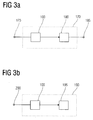
- Fig. 1 shows a schematic block diagram of a first embodiment of an inventive apparatus 100 for analyzing an audio data.
- the apparatus 100 includes a halftone analyzer 110 coupled to a vector calculator 120 for providing an analysis signal to the vector calculator 120.
- the halftone analyzer is coupled to an input port 130 to input the audio data receive.
- the vector calculator 120 is coupled to an output terminal 140 to which the vector calculator 120 outputs an analysis signal of a noninteger Fig. 1 provides shown external component.
- the halftone analyzer 110 analyzes the audio data regarding a volume information distribution over a set of halftones and provides them or optionally a derived distribution to the vector calculator 120.
- the vector calculator 120 now calculates a two-dimensional intermediate vector based on the volume information distribution or the distribution derived from the volume information distribution for each semitone or element of a definition set over which the derived distribution was determined. Subsequently, the vector calculator 120 calculates a sum vector based on the two-dimensional intermediate vectors and outputs it as an analysis signal at the output terminal 140.
- Fig. 2 The method according to the invention for analyzing an audio datum and the mode of operation or the procedure for analyzing an audio datum by means of the device 100 according to the invention are graphically illustrated.
- the halftone analyzer 110 analyzes it over a set of half-tones, thus obtaining a volume information distribution which is exemplified in FIG Fig. 2 shown on the top left.
- the volume information distribution shown there has two contributions 150-1 and 150-2 associated with two different halftones.
- the halftone analysis device 110 of the vector calculation device 120 transmits the volume information distribution, whereupon the vector calculation device 120 transmits a two-dimensional intermediate vector for each semitone calculated based on the volume information distribution.
- the vector calculator 120 calculates an intermediate vector 155-1 for the contribution 150-1 and an intermediate vector 155-2 for the contribution 150-2, both in Fig. 2 shown at the top right. Subsequently, the vector calculation means 120 calculates, based on the two intermediate vectors 155-1 and 155-2, a sum vector 160 which has an angle ⁇ and a length r relative to a preferred direction. The step of calculating the sum vector 160 is in Fig. 2 illustrated lower right. The vector calculator 120 then generates an analysis signal based on the sum vector 160 and outputs it to the output terminal 140.
- the analysis signal can thus have, for example, information regarding the length r and the angle ⁇ of the sum vector.
- the halftone analysis device 110 can have a different structure.
- the decisive factor here is the form in which the audio date exists.
- the audio datum is, for example, a note sequence signal or control signal, ie a signal which, for example, indicates to a tone generator which note or tone it has to play
- the halftone analysis device 110 of the device 100 for analyzing an audio datum can determine the relevant one Store note sequence signals in a memory.
- the halftone analyzer 110 may then assemble or "sum up" all of the note sequence signals associated with a particular semitone, based on the note sequence signals stored in the memory, to be subsequently provided as a volume information distribution to the vector calculator 120.
- the volume information distribution can be weighted according to a number of note sequence signals belonging to a particular semitone. Do the note sequence signals have volume information
- the halftone analyzer 110 can win the volume information distribution over the amount of half-tones by compiling the corresponding note sequence signals.
- note sequence signals are, for example, midi signals (musical instrument digital interface) or other digital or analogue control signals for tone generators.
- an analog or a digital audio signal is provided to the inventive apparatus 100 for analysis of an audio data, then it may be necessary for the halftone analyzer 110 to analyze for a frequency composition in order to achieve the volume information distribution over the amount of semitones.
- digital audio signals as the audio data
- such an analysis can be carried out, for example, by means of a so-called constant-Q transformation.
- the incoming audio signal is analyzed by a plurality of bandpass filters, each characterized by a central frequency and a bandwidth.
- the central frequency of a bandpass filter is used according to the frequency or fundamental frequency of a tone.
- the fundamental frequency of a tone in this case coincides with the central frequency of the bandpass filter, which is responsible for an analysis of the audio data with respect to this tone or half tone.
- the bandwidth of the filters here corresponds to the distance between two tones in the frequency domain, so that the quotient of the central frequency and the bandwidth of each filter is constant. This fact is also taken into account in the designation of the Constant-Q transformation, since the letter Q stands for quotient here.
- Examples of digital audio signals are PCM (Pulse Code Modulation) signals, such as those used with CDs. Depending on which digital audio signals are used, may require further conversion to PCM signals or other digital audio signals. An example of this is, for example, an MP3-coded audio signal.
- analog audio signals as the audio data
- a conversion or sampling of the analog audio signals into a digital audio signal may be necessary before a corresponding constant Q transformation can be carried out.
- ADC analog-to-digital converter
- Examples of analog audio signals are analog microphone signals, analog headphone signals or line signals, such as those used in the field of stereos.
- a tone quality analyzer may be coupled between the halftone analyzer 110 and the vector calculator 120 which calculates a tone volume information distribution over the set of pitch grades as a definition quantity based on the volume information distribution over the set of half-tones.
- a tonality means an information regarding a sound neglecting the octave to which the sound belongs.
- a tone is determined by specifying the tonality and the octave, that is to say, to which octave the tone belongs.
- the notes C, C ', C ", C' ', ... have the tonality C.
- twelve pitches are defined on the piano: D, Dis, E, F, F sharp, G, G sharp, a , Ais, (B or H), C and Cis.
- the halftone analyzer 110 may further consider a frequency-dependent weighting function g (f) in the determination of the volume information distribution, which weights the analyzed halftones depending on their pitch or their fundamental frequency f.
- a frequency-dependent weighting function g (f) it is possible to take into account how different the influence of two tones or semitones of the same tonality but different frequency, and thus different octaves, on the perception of harmony in the case of a multi-sound.
- the vector calculator 120 may be implemented such that each halftone or tonality is associated with a two-dimensional unit vector which is weighted or multiplied by the associated component of the volume information distribution or distribution derived from the volume information distribution.
- the vector calculation device 120 can do this for example on the basis of Cartesian coordinates with the aid of a corresponding arithmetic unit.
- the subsequent calculation of the sum vector 160 on the basis of the intermediate vectors can be carried out with the aid of a (digital) arithmetic unit based on Cartesian coordinates.
- the analysis signal may include the length r and the angle ⁇ of the sum vector relative to a preferred direction in the form of a digital data packet.
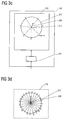
- FIG. 11 shows an escort system 170 comprising an audio data analysis apparatus 100 according to the invention.
- the audio data is provided to the escort system 170 and thus to the device 100 at a companion system input port 175.
- the escort system 170 further includes an escort device 180 coupled to the audio data analysis apparatus 100 such that the escort device receives the analysis signal output from the device 100.
- the accompaniment device 180 can identify, for example, the currently played key and / or the currently played chord, depending on the layout. Based on this information, the escort device 180 can in turn generate corresponding note signals and output to the escort system output 185.
- To the escort system exit 185 can be an in Fig. 3A not shown sound generator can be connected, the note signals of the escort system 170 can convert into audible signals.
- the escort device 180 may, for example, be configured to associate with an amount of note signals output at the escort system output 185 based on a mapping function that associates the angle ⁇ of the sum vector 160 with a set of note signals.
- a mapping function that associates the angle ⁇ of the sum vector 160 with a set of note signals.
- the accompaniment system 170 may be extended by a melody detector and a melody generator coupled together.
- the melody detecting means detects a melody signal which is, for example, the audio data supplied to the device 100 but also another audio signal, analyzes it for a volume information distribution over a set of half-tones, and provides the melody generating means with this as a melody detection signal.
- the melody generating means in turn, generates a melody note signal based on the melody detection signal, which can be supplied to, for example, an optional tone generator.
- the melody detection device can thus be provided, for example via a suitable input, with a melody audio data, for example vocals via a microphone input or another digital or analog audio signal, which the melody detection device analyzes.
- the melody generating means may generate a melody note signal that may be provided, for example, to a sound generator so that it can replay the soaked melody.
- the accompaniment system 170 is able to simulate, for example, a soaked melody and to accompany it at the same time.
- FIG. 12 shows a measurement system 190 comprising an audio data analysis device according to the invention and a display device 195 coupled together.
- the measuring system 190 furthermore has a measuring signal input 200, which coincides with the input terminal of the device 100 according to the invention.
- the audio datum may be both a note sequence signal and an analog or digital audio signal.
- the audio data analysis apparatus 100 outputs a corresponding analysis signal provided to the display device 195.
- the display device 195 may then visually display to a user the analysis signal in, for example, a graphically rendered form.
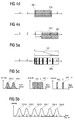
- Fig. 3C shows an embodiment of a display device 195.
- the display device 195 has a display controller 205 which is coupled to an output field 210.
- the display control device 205 receives the analysis signal from the device according to the invention for analyzing an audio datum.
- the output field 210 may include, for example, a liquid crystal display (LCD), a screen, or other optical display surface, such as a matrix array of light emitting diodes (LED).
- the display control device 205 can control the output field 210 such that, starting from a central point 215, any output field radial direction can be optically emphasized.
- this can be realized, for example, by starting a light-emitting diode assigned to the central point 215 and driving a plurality of light-emitting diodes from the display control device 205, which start in a straight line from the central point 215.
- the display controller 205 may be configured to display more complex patterns. In this case, not only an output field radial direction can be emphasized, but more complicated patterns can be displayed. It is thus advisable in this case to represent an arrangement of pitches or tones on the display 210, in the context of which the sum vector, which is supplied by the apparatus 100 according to the invention in the form of the analysis signal, is to be brought closer to a viewer of the measuring system 190.
- Fig. 3C For this purpose, an arrangement 217 designated as a symmetry model or symmetry circle or cadence circle is shown on the output field 210.
- the exact arrangement of the pitches in the symmetry model 217 is related to Fig. 7 explained in more detail.
- the display controller 205 controls the output field 210 such that, starting from the central point 215, the sum vector is displayed in the form of an output field radial direction or a more complicated pattern. In Fig. 3C this is illustrated by the arrow 220.
- the Display controller 205 controls the output field 210 so that the arrow 220 appears at an angle relative to a preferred direction of the output field 210, which depends on the angle of the sum vector.
- the display device 195 and the device according to the invention for analyzing an audio data 100 are matched to one another such that the angles of the intermediate vectors, the different semitones or the elements of the definition set are assigned, and the angles at which different pitches are displayed on the output field 210 (eg the symmetry model 217) can be converted into one another by a simple mapping.
- this mapping is a linear mapping, that is, for example, the identity.
- the device 100 according to the invention and the display device 195 are coordinated with each other such that a 1: 1 allocation of the angles of the intermediate vectors assigned to the different pitches or the different elements of the definition set and the directions under which the different pitches on the output field 210 appear, is given.
- the symmetry model 217 and the arrow 220 indicating the sum vector can be displayed on the output field 210 in such a way that the output spatially emulates the symmetry model on the output field.
- the term "spatially replicate” is understood to mean an arrangement in which elements of an arrangement, for example input devices, output field radial directions and output ranges, are arranged relative to a central point such that elements assigned to a particular tonality are located below are arranged at such an angle that they also appear in a tonal space at this angle.
- the length of the sum vector can also be displayed over the length of the illustrated arrow 220.
- the length of the arrow 220 and the length of the sum vector can be linked together via a function, which may be implemented, for example, within the scope of the display controller 205.
- a function which may be implemented, for example, within the scope of the display controller 205.
- a simple linear assignment can also be made, such as a logarithmic, a quadratic or another, possibly more complicated mapping of the length of the sum vector to the length of the arrow 220 shown.
- Fig. 3D shows a second embodiment of a possible representation on the output field 210.
- output field 210 is on the in Fig. 3D shown output field 210 not the symmetry model 217, but an arrangement of pitches shown, which is referred to as a circle of thirds 217 '.
- the symmetry model is related to the Fig. 8 - 14 explained in more detail why reference is made to the corresponding sections in the context of the present application at this point.
- tonicities In the notation of the tonicities, a distinction is made between uppercase and lowercase tonicities in the context of the present application. If a tonality is denoted by a capital letter, such as C or F, then the corresponding major triad sounds when the tone of sound in question and the two pitches that follow the tone in a clockwise direction. In the case of C, this means that the pitches C - e - G represent a C major triad, for example. Accordingly, the three pitches F, a and C together represent an F major triad. Tonalities denoted by lower case letters represent minor triads, respectively. An example of this is, for example, the d minor triad, which represents the Tonalities d, F and a includes.
- a special position is occupied by the triad designated h0, which is the diminished triad h0, when, starting from the tonality h0, the two tone pitches following in the clockwise direction resonate. So this is the Triad h - d - F, consisting of a sequence of two minor thirds.
- the output field 210 is not a screen or a screen-like output field, which passes on optical means information to a viewer, but that this is, for example, a mechanical output field, in the individual output field radial directions, Output field areas or parts of the output field can be mechanically highlighted. It is conceivable in this context that such emphasis can be made by a mechanical vibration or by raising or lowering of a certain area. This makes it possible to offer visually impaired people a corresponding presentation.
- the display controller 205 may also be configured to emphasize an output field radial direction of the output field 210 or a portion of the output field 210 associated with a tone quality of the symmetry model 217 or the third circle 217 'when a corresponding signal is communicated to the display controller 205.
- pitches or semitones may also be displayed on the output panel 210.
- Particularly useful in this context are arrangements of pitches in which adjacent pitches are associated with pitches, which are based on particular music-theoretical relationships.
- the choice of a specific output field preferred direction here is not a restriction to the term "adjacent angle" or "immediately adjacent angle". Therefore, for example, an angle, which is assigned a Tonmaschine and which is at an angle value of 359 °, immediately adjacent to another Angles are the one Tonality is assigned and which is at an angle value of 1 °.
- Fig. 3E 1 shows a detection system 230 which, in addition to the device according to the invention for analyzing an audio datum 100, also includes an integrator device 240 and an evaluation device 250.
- the integrator device 240 is provided at one input with a time-dependent audio input signal which integrally integrates the integrator device 240 and provides it as an edited audio datum of the inventive device 100 at an output.
- the integrator device 240 can be configured such that the number of portions of the note sequence signal relating to a tone is added up.
- a weighting may take into account the volume information that may include the grade-following signal as well as other weighting factors.
- the integrator device 240 can take into account the "age" of a note sequence signal, ie a time difference between the arrival of a note sequence signal and a current time index. In this case, the integrator device 240 can provide the audio device in the form of a further note sequence signal to the device 100 according to the invention.
- the time-dependent audio input signal is an analog or digital audio signal, for example an analog microphone signal
- the integrator device 240 of the device 100 according to the invention can provide the audio data in the form of a further note sequence signal, for example by the integrator device 240 generating corresponding Midi signals based on an analysis by constant Q transformation and outputting the device according to the invention.
- the evaluation device 250 is connected, which receives the analysis signal from the device 100.
- the analysis signal of the device 100 in this case preferably comprises the length of the sum vector.
- the integrator device 240 is designed such that it provides the time-dependent audio input signal as an audio datum to the device 100 at regular intervals, for example, the device 100 carries out the analysis at regular intervals at a predetermined frequency and outputs the respective analysis signal accordingly.
- the evaluation device 250 based on the incoming analysis signals determine a time course of the length of the sum vector, analyze and, if the temporal course of the length of the sum vector has a maximum or a minimum, output a detection signal at an output of the detection system 230.
- the detection system 230 is able to detect, for example, a chord change or a key change. More details on this topic will be explained in the further course of the present application.
- the integrator device 240 can also be supplied with the detection signal of the evaluation device 250, as shown in FIG Fig. 3E Dashed line connection between the output of the evaluation device 250 and the integrator 240 shows.
- the detection system can be restored to an original state so that a new detection can be performed without "older" time-dependent audio input signals influencing the result of the detection ,
- the detection system can also be realized such that the integrator device 240 is switched between the halftone analysis device 110 and the vector calculation device 120.
- the detection system can also be designed so that the integrator device 240 is executed as an optional component of the device 100 according to the invention.
- the integrator device 240 may be implemented such that it makes available, on the basis of the volume information distribution, a distribution derived therefrom from the vector calculation device or from a downstream tone quality calculation device.
- Tonartbeéesssystem which, in addition to an inventive device for analyzing an audio data having a Tonartbeticians raised, which is coupled to the inventive device.
- the key determination device receives the analysis signal from the device according to the invention and analyzes the current key or, alternatively, the current chord based on the angle of the sum vector included in the analysis signal.
- the key determination device can do this, for example based on a key assignment function which assigns the angle of the sum vector to a key or a chord. More detailed explanations will be given in the further course of the present application in the context of the "symmetry model", the "circle of thirds" and their mathematical description.
- the key determining means may also provide an estimate of the reliability of the analysis based on the analysis signal.
- the length of the sum vector which is also included in the analysis signal, is used as a basis.
- the estimated value can be based on a further functional assignment, which assigns a length value of the sum vector a certain estimated value.
- This further functional assignment may include a simple linear mapping, a step function, or a more complicated function.
- the key determiner outputs the key and, optionally, the estimate as a key signal at an output that can be output to an optional display device, for example.
- the chromatic scale consists of a sequence of twelve semitones, each having a pitch of a small second.
- the chromatic scale includes twelve semitones that belong to one octave.
- Each sound and halftone is therefore associated with a frequency of a sound wave or other mechanical vibration.
- each sound and half tone of a particular octave and within an octave of a certain tonality can be assigned. In other words, this means that a semitone is uniquely determined by the octave and its tonality.
- a prime or prime interval denotes a pitch of one semitone, counting the start and end tones.
- two tones in a prime distance have the same frequency or fundamental frequency (frequency ratio of the tones 1: 1), so that it is the same tone.
- a pitch of two semitones is understood, in which case again the two tones that form the interval are counted.
- a pitch of four semitones is understood by a minor third or a minor third pitch, an interval of five semitones by a major third and a major third pitch, and an interval of eight semitones by a fifth or fifth pitch, respectively Sounds that form the interval are counted.
- an oval / circular arrangement of the base tones is generally used as the basis.
- an oval / circular arrangement is understood to mean an arrangement in which, with respect to a central point, the elements of the arrangement, in this case the output areas, at a plurality of angles with respect to a zero direction or a preferred direction with one of the Angle dependent radius are arranged.
- a difference between a maximum occurring radius and a minimum occurring radius typically differs from an average radius of less than 70% and preferably less than 25%.
- the plane section or spatial section comprises at least one input angle or an input angle range.
- the selected room section can be infinitely or abruptly changed in its extent and in its center of gravity, so its location.
- assign the selected room section with a selection weighting function.
- the Selection weighting function allows you to define the relative volume at which the basic tones or pitches recorded by the room section are to be played. So basic tones are placed at discrete positions of the tonal space.
- a spatial tone distribution function is defined in addition to the selection weighting function.
- Each basic tone or tone quality placed in the tonal space has such a function, which in this case is referred to as a spatial single-tone distribution function.
- the spatial tone distribution function thus ensures that a tone not only occupies an infinite small discrete point or, in the case of an oval / circular tone space, a single angle, but rather a spatial section or finite angular range.
- the space cut-outs occupied by two basic tones can overlap here. It can thus also be associated with an angle more than one tonality, in particular two pitches.
- the principles presented here thus offer completely novel possibilities in the design of polyphonic audio signals, as will be apparent from the description of the exemplary embodiments in the further course of the present application.
- Fig. 4A shows a schematic representation of an imaged on a straight angle range with an assignment of pitches, here for the sake of simplicity, the pitches are not denoted by large and small letters to specify the associated tone (minor triad or major triad) in more detail.
- the direction of the arrow indicates the direction of increasing angle or clockwise direction.
- the basic tones G, B or H, D, F, A and C are placed in the one-dimensional tonal space.
- a space section 300a having the tones of the D minor chord (D-F-A) is selected.
- a connected tone generator would play a d minor chord. By selecting the space section 300a, a d minor chord would thus be created.
- Fig. 4B is the tonal space that is in Fig. 4A already shown was shown again.
- a space cut 300b is shown which is very small compared to the space cutout 300a.
- the space section 300b has an extent that almost disappears or is zero, which would correspond to a selection of a single angle, that is to say a single input angle.
- the room detail 300b is located directly on a base tone, namely the base tone D.
- a connected tone generator would now play a single tone D.
- Fig. 4C is in turn already in Fig. 4A shown space section shown.
- Fig. 4C shows how the room detail 300b, which is already in Fig. 4B has been shown, is moved from the position of the base pitch D continuously over a position of a space section 300c in a center position between the base pitch D and the base pitch F, so that the space 300b at the end of its movement has moved into a space cutout 300d.
- a connected tone generator would according to the position of the space section 300b, 300c or 300d the loudness of the sound D hide and fade the sound F volume-based, if appropriate volume information be taken into account. Details relating to the fade in and fade out of tones are enabled by the selection weighting function and the spatial tone distribution function, which will be discussed further below. So while Fig. 4B shows a generation of a single tone shows Fig. 4C a fading between adjacent base tones.
- Fig. 4D an example of a transition between a single tone and a chord is shown. So is in Fig. 4D turn the already in Fig. 4A shown tonal space shown.
- the selected room cutout starts from the room cutout 300b Fig. 4B continuously expanded to a width of a triad, which corresponds to a space 300e.
- An attached tone generator would initially play only the D sound again. Subsequently, during the extension of the selected spatial section, the sound F would be slowly faded in and then the sound A would be subsequently "converted" into a D minor triad.
- Fig. 4E a transition between different chords is illustrated.
- Fig. 4E shows as the room section 300e Fig. 4D is continuously shifted so that it merges into a new space 300f.
- the space section 300f then begins no longer with the sound D, but with the sound F. So a connected sound generator would initially play a D minor chord and then fade it continuously into a F major chord.
- Fig. 5A the effect of a selection weighting function is illustrated. So shows Fig. 5A turn the already off Fig. 4A known tonal space.
- the selected section of room will include tones D, F, A and C.
- a connected tone generator would play a D minor 7 chord in which all tones have the same volume.
- a selection weighting function 305 as also shown in FIG Fig. 5A is shown, the volume of each tone can be adjusted.
- the selection weighting function 305 is chosen to place emphasis on the root D and third of the chord and that the fifth and seventh C be played at a reduced volume.
- each base tone is assigned a spatial tone distribution function 310-C, 310-A, 310-F, 310-D, 310-B and 310-G in this example.
- each base tone is not only associated with a discrete location or angle, but also defined in a certain environment around the base tone.
- assigned to each base pitch a bell-shaped spatial single-tone distribution function.
- FIG. 5C three examples of different spatial distribution functions or spatial sound distribution functions are shown. More specifically shows Fig. 5C three examples of spatial single-tone distribution functions, which are shown assigned to their respective basic tones and Tonmaschineen.
- the two spatial Einzeltonver notorioussfunktionen 310-C and 310-E have at their respective base tones and Tonmaschineen C and E a maximum volume information in the form of an intensity. Starting from the basic tones C and E, the volume information drops rapidly.
- the two pitches correspond, for example, if the input angle is in this range of Tonraums.
- FIG. 5C shows another possibility of a spatial single-tone distribution function.
- two rectangular-shaped spatial single-tone distribution functions 310'-C and 310'-E are shown.
- the two spatial Einzeltonver notorioussfunktionen 310'-C, 310'-E each extend from their associated base tone C and E on both sides over an angular range or space, which corresponds to half a distance between two adjacent basic tones in the sound space. Within these areas of space, the volume information in the form of the intensity is constant in this example.
- the two spatial Einzeleltonver notorioussfunktionen 310'-C and 310'-E not.
- Fig. 5C on the right is a third example of two spatial single-tone distribution functions 310 "-C and 310" -E above the already on the left in FIG Fig. 5C shown tonal space shown.
- the angular regions or spatial regions in which the two spatial single-tone distribution functions 310 "-C and 310" -E have non-zero volume information are significantly reduced.
- these two spatial Einzeltonvertechniksfunktionen are rectangular, so that regardless of the exact position within the space area in which the two spatial Einzeltonver notorioussfunktionen have a non-zero volume information, this is always constant.
- the sound C will sound for a short time while the input angle or range is within the space in which the spatial single-tone distribution function 310 "-C has non-zero volume information If, for example, the very small input angle range has left this range, the connected tone generator would produce no sound, so that in this case there is silence., Then the input angle or even the very small input angle range reaches the spatial area where the spatial single-tone distribution function 300 "-E has zero volume information, the sound E will sound.
- the two pitches C and E which in Fig. 5C are shown to have a smallest pitch, which corresponds to a large third of a third.
- the two pitches C and E also have different pitches than those of a major third. This is due to the fact that basic tones or pitches have no information regarding the octave or octave position. For this reason, the two pitches C and E, for example, also a pitch of a small sixth, which is greater than the smallest pitch, which corresponds to a major third.
- the opening angle of the symmetry circle or of the selected spatial section can also be interpreted as a "jazz factor".
- oval / circular arrangement is understood to mean an arrangement in which, relative to a central point, the elements of the arrangement, in this case the output areas, are arranged at a plurality of angles with respect to a zero direction or a preferred direction with a radius dependent on the angle ,
- a difference between a maximum occurring radius and a minimum occurring radius typically differs from an average radius of less than 70% and preferably less than 25%.
- Fig. 6 shows four examples of a representation of pitches on an output field 210 as shown in FIG 3C and 3D is shown.
- the oval / circular arrangement of the output field radial direction and the output ranges has been "bent" to a straight line to simplify the presentation.
- the oval / circular arrangement of the output field radial directions or the underlying angular range has thus been mapped onto a straight line.
- a more compact representation of the output field 210 is possible with different tones, sound combinations and sound combinations displayed.
- the in the Figs. 6A-6D In this case, the arrows indicate the direction of increasing angles or the clockwise direction.
- the Figs. 6A-6D is such a sound space, which includes the pitch classes G, B and H, D, F and A, respectively.
- Fig. 6A shows the case when the display controller 205 is notified of sounding with a tone D.
- the display controller 205 controls the output field 210 so that the tone (or pitch) corresponding to the tone is marked in the tone space of the output field 210, that is, when the corresponding tone sounds.
- a marking or a highlighting 320-D appears on the output field 210, which is, for example, an optical signal, that is to say a lighting up of a corresponding region of the output field 210.
- an optical signal that is to say a lighting up of a corresponding region of the output field 210.
- Fig. 6A the example shown sounds the sound D, which is then displayed on the output field 210.
- Fig. 6B shows the case that several sounds sound at the same time, resulting in a meaningful sound combination.
- adjacent base tones are highlighted in the tone space displayed on the output field 210.
- the spatial concentration of active basic tones or tonalities in the tonal space is a measure of the meaningfulness, ie, of the perceived consonance.
- Fig. 6B this on the basis of a D minor chord, which corresponds to a meaningful sound combination.
- the base tones D, F and A are emphasized by respective markings 320-D, 320-F and 320-A.
- the corresponding basic tones in the sound space and thus on the output field, which spatially replicates the sound space are very far apart. It can be deduced from this that the spatial extension of active basic tones in the tone space is a measure of the meaninglessness, ie of the perceived dissonance.
- the tones G and A are sounded, so that a corresponding activation signal is made available to the display control device 205, so that on the output field 210 the associated base tones G and A are marked by the markings 320-G and 320-A.
- the interval produced by these tones is one second, which is generally perceived as being relatively dissonant-sounding.
- Fig. 6C thus shows a marking of the tonal space on the output field 210 when sounding a little meaningful sound combination, more precisely a second.
- Fig. 6D shows an example of a display on a corresponding output field 210 for a D minor chord.
- markings 320-D, 320-F, and 320-A are also marked, but a region 325 is also displayed that includes the ringing tones or their markings.
- the location of the center of gravity is also represented by an additional mark 330.
- Fig. 7 shows a graphical representation of the symmetry model in the form of the so-called cadence circle for the C major scale and for the A minor scale.
- symmetry model and “cadence circle” are used partly synonymously.
- the symmetry model positions the seven tones of the diatonic scale or the seven pitches of the diatonic scales 305-D, 350-F, 350-A, 350-C, 350-E, 350-G and 350-B on a circle or an oval / circular arrangement.
- a novelty here is above all the order of the notes on the circle.
- the tones or pitches are not at equal intervals, but - starting with the second tone 350-D of the scale, so the sound D - alternately positioned in small and large thirds at a defined angle on the circle.
- a second, very important feature is the symmetrical arrangement of the tones around an imaginary axis of symmetry 360.
- the axis of symmetry 360 passes exactly through the location 350-D of the second tone of the scale (D), which is why it is also referred to as symmetry tone.
- the remaining or further notes of the scale are positioned symmetrically to the left and right around the symmetry tone 350-D.
- Fig. 7 is an example of such a minor third between the two tones E and G, as well as an example of a major third 385 drawn between the two tones G and B.
- Fig. 7 thus shows overall the arrangement of the basic tones in the tone space according to the symmetry model.
- the tones are - as already mentioned - symmetrically positioned around the axis of symmetry D 350-D extending symmetry axis 360.
- the symmetry results from the pitches of the basic tones.
- the tones or pitches 350-E to 350-C are therefore not distributed equidistantly with respect to the angle on a circle. Rather, they are correspondingly spaced relative to the respectively smallest pitch of their neighboring tone or to their neighboring tone.
- an angle associated with a particular tone or tone may be made by introducing an identifier n '.
- the identifier n ' can not only represent the angle ⁇ T of the pitches with respect to one octave, but also allows a representation of all tones of the corresponding major scale.
- an area of the in Fig. 7 understood Symmetriemodells comprising the four pitches A (350-A), C (350-C), E (350-E) and G (350-G), that is located in the region of the tonal center 390.
- An area called the dominant area extends at the in Fig. 7 selected representation as a symmetry model starting from the tonal center 390 in the clockwise direction to approximately in the region of the symmetry tone D (350-D).
- the dominant range includes the four pitches E (350-E), G (350-G), B and H (350-H) and D (350-D).
- an area called a subdominant area extending from the tonal center 390 counterclockwise also extends to the symmetry tone D (350-D), where the pitches C (350-C), A (350-A), F (350 -F) and D (350-D).
- the symmetry model allows a more playful and thus pedagogically more valuable approach to music theory principles compared to the diatonic scale, which will be summarized and explained again below.
- the main focus is on the transmission of music theory knowledge Children.
- Educational-music theory principles are usually very opaque.
- the toddler musical instrument described herein is such an input method that is so simple that even toddlers or severely disabled persons can be musically creative.
- the tonalities are not arranged on a line like the piano, but on a circle, namely the symmetry circle of the symmetry model. In principle, other oval / circular arrangements, as defined in the introductory sections of the present application, are also conceivable here.
- the circle has a circle center. Through the circle center is a vertically extending, imaginary axis, which is referred to below as the axis of symmetry 360.
- each pitch 350-C to 350-A can be represented by an angle ⁇ between the axis of symmetry 360 and a connecting line between the respective pitch and the center of the circle.
- the white keys on the piano are equally wide, whether two adjacent keys represent a whole-tone step or a half-tone step.
- the pitches are not arranged at equal intervals or due to the oval / circular arrangement at equal angles, but in a (angular) distance corresponding to the pitch or Tonsprung between the two pitches. That is, two adjacent pitches corresponding to a (smallest) pitch of a major third are located farther apart on the circle and the circle of symmetry than two pitches associated with a (smallest) pitch corresponding to a minor third.
- the distances of the individual pitches to one another represent the (smallest) pitch of the assigned tones or pitches.
- the pitches are then positioned on the circle as follows:
- ⁇ 180 ° with respect to the circle center
- a zero direction in Fig. 7 runs vertically upwards.
- the following table shows an example of the exact angles of the tonicities 350-C to 350-A. However, it is important to note at this point that a different distribution in terms of angles is possible.
- the tonal area which includes the pitch classes C and E, is assigned the color yellow.
- the dominant area which includes the pitch classes G and B, is assigned red or orange.
- the subdominant area which includes the pitches A and F, is assigned blue, while the area comprising the pitch D is assigned the color violet.
- This coloring is based on a "feeling of warmth", wherein the subdominant area bluish colors are assigned, as this is associated with “cold”. Reddish tones are assigned to the dominant area, as this is associated with “heat”.
- the tonic region is assigned the color yellow as the "neutral region", while the region in which the subdominant region and the dominant region abut each other is assigned violet.
- the tonicities different from the representation in Fig. 7 , are provided with symbols that symbolize major triads or minor triads as well as diminished triad.
- One possibility is the already explained use of large and small letters.
- the circle of thirds represents connections that are trans-parent, as in Fig. 8 is shown.
- the circle of thirds not only maps the seven tones of a diatonic scale in the tonal space, but all twelve tones of the chromatic scale oval / circular or in a closing arrangement.
- each base note not only appears once, but twice in the circle of thirds.
- the circle of thirds therefore contains 24 tones or pitches.
- the order of the tones essentially corresponds to the sound order of the symmetry model.
- the notes are arranged in thirds of a third, alternately in small and major thirds.
- Fig. 9 shows a section of the in Fig. 8 shown third circle.
- Diatonic keys such as C major or A minor are represented in the circle of thirds by a single contiguous circle segment.
- Fig. 9 such a circle segment 400, which corresponds to the key of C major or A minor.
- the circle segment 400 is bounded on both sides by the symmetry tone D of the key.
- An axis of symmetry 405 extends through the center of the circle segment. If this circle segment 400 is removed from the circle of thirds and unfolds like a fan so far that the two straight sides touch, then the symmetry model described in the previous sections results.
- Fig. 9 thus shows a representation of a diatonic key in the circle of three.
- Fig. 10 the similarities of two neighboring keys are illustrated. For this purpose is in Fig. 10 that already in Fig. 9 shown circle segment 400, which corresponds to the key of C major and A minor, together with another circle segment 400 'shown, which corresponds to the key F major. Neighboring keys such as C major and F major are thus directly adjacent to each other in the circle of thirds. At the in Fig. 10 chosen representation are common. Sounds in an area represented by overlapping circle segments.
- Fig. 11 illustrates in a section of the circle of the third circle that the symmetry axis of a diatonic key, for example the symmetry axis 405 of the key C major, runs exactly through a center of gravity 410 of the circle segment 400 representing the key.
- the center of gravity 410 of the area 400 of a diatonic key in Fig. 11 the key C major
- the circle of thirds is also excellent for depicting kinship relationships between keys.
- Related keys that is, keys having many common tones, are shown adjacent in the circle of thirds. Clays that have very little to do with each other are positioned far away in the circle of thirds.
- the type and number of the number of signs belonging to a key can be easily determined.
- a symmetry axis 405 'of the key F major is shown, which is rotated in the circle of thirds with respect to the axis of symmetry 405 by 30 ° counterclockwise.
- the keys C major and F major differ only slightly with respect to the seven notes of the underlying diatonic scale.
- the key F major has an additional sign (b) compared to the key C major.
- a corresponding consideration also applies to the key G-major, which is represented by an axis of symmetry 405 ", unlike the key of F major, the key G major has a signed # .
- the symmetry axis 405" is for the key G major opposite the symmetry axis 405 for the key C major in the circle of thirds rotated by 30 ° clockwise.
- Fig. 13 illustrates that in contrast to other basic tonal arrangements, such as. B.
- a chromatic arrangement in Fig. 13 is shown on the left, common tones of adjacent keys in the circle of thirds lie next to each other without gaps, like the Fig. 13 illustrated on the right. So is in Fig. 13 on the right side belonging to the key C major circle segment 400 and belonging to the key F major circle segment 400 'shown.
- the illustration on the right side of Fig. 13 thus corresponds to that of a third octave or third circle.
- This arrangement presents Fig. 13 a chromatic base tone arrangement to the left.
- the individual segments 400a-400e and the circle segments 400'a-400'e correspond to the circle segments 400 and 400 ', as they are in FIG Fig. 13 are shown on the right.
- Fig. 13 thus shows that the circle of thirds is significantly better in terms of kinship relationships between adjacent keys compared to a chromatic base pitch arrangement.
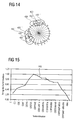
- Fig. 14 shows that the principle of sixfold tone utilization in the circle of three is perfectly depicted or represented.
- Fig. 14 shows Riemann's principle of the sixfold tone utilization on the example of the tone or the tone quality.
- a tone can be the root, third, and fifth of both a minor chord and a major chord.
- the tone or tonality C appears in the circle of two at two positions 420, 420 '. More specifically, the tone C appears in a major context (C major), which corresponds to the position 420, and in a minor context (C minor), which corresponds to the position 420 '.
- the tone C is part of the chords F minor (area 425), A flat major (area 425 ') and C minor (area 425 ").
- the tone C is part of the chords F major (area 430), a minor (area 430') and C major (area 430").
- the symmetry model reflects Riemann's principle of sixfold sound utilization. As Fig. 14 shows, these relationships can be easily derived from the circle of thirds. It remains to be noted that the basic notes of major chords and parallel minor chords continue to lie side by side.
- circle of thirds and the symmetry model is to mirror the circle of thirds and / or the symmetry model respectively about an axis running horizontally in the figures, so that in the case of the symmetry model the tonic area of a certain (major) key is below comes to rest, while the diminished area would migrate upwards.
- a (damped) pendulum is deflected in one direction, then vibrates for a while and then comes to rest sometime. The more the pendulum is deflected to one side, the stronger it also swings in the other direction.
- a pendulum for example, in a center of the symmetry model, such as in Fig. 7 however, which is mirrored about the horizontal axis, is suspended initially suspended in the tonic region. When it is excited to vibrate, it begins to vibrate, and after a while, it ends again in the tonic area. The more the pendulum is deflected into the subdominant area, for example, the more it then swings into the dominant area. Many harmonic progressions of very popular chord progressions within occidental music follow the principle that on chords positioned in the subdominant range are, very often chords follow, which are correspondingly opposite in the Dominant Symposium. Also, many songs and musical works begin and end in the tonic area, which completes the analogy to a swinging pendulum, as described above, impressively.
- the circle of thirds as he, for example, in Fig. 8 is shown, and the symmetry model, as for example in Fig. 7 is shown, always uniformly described and illustrated, of course, a horizontally and / or vertically mirrored positioning variant of the basic tones in the sound field can be used.
- the representation of the exemplary embodiments in the context of the present application is generally based on an arrangement of the basic tones in the symmetry model (cf. Fig. 7 ) and the circle of thirds (cf. Fig. 8 ), this is not to be understood as limiting.
- Mirrored or rotated base tone arrays can thus be used, for example, within the scope of a display device of a system according to the invention, such as a measuring system or a system.
- each tonality t is assigned a base index m t and an extended index n t .
- the base index m t and the extended index n t are both integers, where Z represents the set of integers. The following applies: 0 ⁇ m t ⁇ 11 . m t ⁇ Z - ⁇ ⁇ n t ⁇ + ⁇ . n t ⁇ Z
- the basic index m t is a unique or unique numbering of all 12 pitches.
- the extended index n t captures the fact that the pitch classes can logically form a circle or can be arranged periodically, followed by the first tone quality after the last tone quality. Therefore, it is also desirable that one can continue counting the extended index n t infinitely.
- the circle of thirds consists of 24 notes separated by major and minor thirds. These tones are referred to as real tones r because they actually represent sounding tones. In order to be able to place the real tones r geometrically on the circle of thirds, it is necessary to add auxiliary tones h.
- Two adjacent auxiliary tones have a semitone spacing (second) and, like the pitch classes, have a basic index m h and an extended index n h . Two adjacent auxiliary currents thus have the extended indices n h and (n h +1). Similar to the previous section: - 42 ⁇ m H ⁇ + 42 - ⁇ ⁇ n H ⁇ + ⁇
- the auxiliary tones h are used to define the 84-element halftone screen behind the circle of thirds: the basic index m h of the auxiliary tones h does not run from 0 to 11, as in the case of the pitch classes, but from -42 to +41, like the equation 5 shows. Auxiliary notes, which contribute to the definition of keys with negative sign (b-keys), thus receive a negative sign. Auxiliary notes, which contribute to the definition of keys with positive signs (cross keys or # tones), have a positive sign.
- Each auxiliary tone h with the extended index n h is assigned a tone quality t with the extended index of the tonality n t .
- Equation 4 The conversion of the extended index n t into the basic index m t of the pitch classes t then takes place according to equation 4.
- every helper h with the extended index n h can also be a vector H n H be represented or presented.
- This vector H n H has an angle ⁇ with respect to a zero vector.
- the vector H o is therefore called the zero vector.
- each auxiliary tone is also assigned a length or an amount, which is also referred to below as the energy s of the auxiliary tone.
- the energy s of the auxiliary h is found in the form of the magnitude of the vector H n H again.
- auxiliary tones h there are still the real tones r.
- the real tones are the 24 tones actually present on the circle of thirds and form a subset of the set of auxiliary tones M h .
- Each real r is either the root of a major chord (+) or the root of a minor chord (-). For this reason, the set of real tones M r can be divided into a subset M r + and M r- .
- M r ⁇ : H n H
- n H 7 k ⁇ 2 . k ⁇ Z
- Every tonality t is found on the circle of thirds in the form of two real tones r, namely once as the root of a major chord r nr + and as the root of a minor chord r nr- .
- Equation 12 shows a calculation rule with which for a given tonality t with an extended index n t the corresponding one-circle real tones r nr- and r nr + can be found.
- the mathematical description of the symmetry circle is similar to the description of the circle of three.
- the following explanations apply only to unsigned diatonic keys such as C major or A minor.
- a so-called transposition factor ⁇ must be introduced in order to detect the fact that the symmetry circle is related to a specific diatonic key.
- the symmetry circle or the cadence circle of the symmetry model contains seven real tones r m at intervals of small and major thirds. These are placed on a halftone screen consisting of 24 auxiliary tones h.
- Each of the auxiliary tones h also has a base index m h and an extended index n h , by means of which a helper h on the circle of thirds can be uniquely identified.
- the indexing of the auxiliary tones h in the circle of three is chosen so that auxiliary tones h with a negative index, more precisely with a negative base index m h , belong to the subdominant range and auxiliary tones h with positive index or basic index m h belong to the dominant range.
- indicates that the real r is close to the tonic region and the tonal center, respectively.
- is a measure of how far away a tone is from the tonic area or the tonal center.
- Each helper h with the extended index n h can also be called a vector H show nh .
- this vector H nh has an angle ⁇ which is chosen so that the symmetry pitch of symmetry represented by the circle key h 0 receives the angle 0th
- the vector H 0 is therefore also called the zero vector.
- a set of given pitches M t can also be represented in the symmetry circle by a sum vector r sum be described.
- the symmetry circle does not contain all tones, but only the tones of the selected diatonic key. If one wants to represent a set of given pitches M t on the circle of thirds, one must first form the intersection M t ⁇ M r from the given pitches M t and the real tones existing on the symmetry circle or the set of real tones M r present on the symmetry circle , For this intersection one can then use the sum vector r sum up.
- an arbitrary set of pitches may be in the form of a sum vector r sum summarized and described. This provides valuable information about the content characteristics of the underlying audio or audio signal.
- the angle ⁇ of the sum vector shows r sum in which key a piece of music is at a certain point in time.
- is also an estimate that describes how certain it is that there is a particular diatonic key or how defined the tonal context is. If the amount is very large, then it is fairly certain that the tonicities belong to a certain key. In other words, as the magnitude of the sum vector
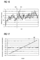
- Fig. 15 shows an example of the definition of the tonal context in different sound combinations. More specifically shows Fig. 15 a curve 440 of the magnitude of the sum vector for various recorded on the abscissa tone combinations or Tontechnikskombinationen.
- becomes so long or remains essentially in its length, as long as the Amount of pitches tonal pitches are added.
- the amount of the sum vector, starting from the individual tonality C increases by adding further C-major pitch-inherent pitches until it reaches a maximum value with a tonality combination CDEFGA. Adding the likewise C major own tone quality B or H results in only a slight decrease.
- the sum vector also provides information about key changes or modulations:
- a key on the circle of three takes a range of 24 semitone steps. This corresponds to an angle of 4/7 n. If a piece of music remains within the limits of a diatonic key, then the sum vector moves r sum in a circle segment that does not exceed this opening angle. Leaves the sum vector r in contrast, if such a circle segment, then there is probably a key change.
- Fig. 16 shows a course of the angle of the circle of three-circle sum vector r sum at a piece of Bach. More specifically shows Fig. 16 a curve 450 of the angle of the sum vector r sum for the first ten seconds of Bach's Brandenburg Concerto No. 1, Allegro. Chord changes and key changes can be recognized by larger angle changes. An example of this is the time indicated by dashed lines 455. The key represented by an angle can be determined by means of equations 15a-15c.
- the sum vector r sum also makes it possible to correct analysis errors in harmony analysis and key analysis. Modulations to adjacent keys are more likely than modulations to non-adjacent keys. Rare short-term outliers of the angle of the third circle sum vector indicate that there is a high probability that an analysis error will be required.
- the audio signal underlying the analysis is integrated over time until the magnitude of the resulting sum vector has a maximum, this indicates a key change.
- a detection system such as Fig. 3E shows, in the context of the evaluation device 250 to introduce a corresponding corrective element approximately in the form of averaging over a period of time filter element.
- the circle of thirds and the orbital-based harmonic analysis are used to analyze key-system-related relationships.
- the third tone used can be determined from a tone signal or audio signal or audio data. If the key is determined or given, then the symmetry model can be determined or used. This in turn is very well suited to determine relationships within a key.
- the symmetry model-based harmonic analysis also introduces the sum vector introduced in the section on the mathematical model description of the symmetry model r sum used.
- From the angle of the sum vector r sum is the momentary chord, as it points to the geometric center of gravity or the tonal center of the pitches played at one time.
- chord changes are determined or analyzed. A sudden change in the angle of the sum vector suggests a chord change.
- the angle of the symmetry circle sum vector also indicates whether a tone combination tends to be assigned to the subdominant region, the tonic region or the dominant region.
- Fig. 17 shows a curve 465 of the angle of the symmetry circle sum vector (in radians) for different chords. Fig. 17 indicates that a tone combination is to be assigned to the subdominant domain if the angle has a negative sign. On the other hand, if the angle has a positive sign, then the sound combination is to be assigned to the dominant area. The larger the angle of the sound combination is in terms of magnitude, the stronger the sound combination protrudes into the corresponding area. An exception to this is the triad B-diminished or H-diminished, respectively, in Fig.
- Fig. 18 shows the angle of the symmetry circle sum vector for different triads, whereby the symmetry circle is based on the key C-major or a-minor.
- Fig. 18 shows a course 470 of the amount of the symmetry circle sum vector
- Fig. 18 shows that the amount of the symmetry circle sum vector becomes steadily smaller with decreasing consonance.
- the magnitude of the angle of the symmetry circle sum vector r Thus sum can be interpreted as an estimate of a resolution effort of a certain tone combination within the context of an existing tonal context (key).
- the course 470 illustrates that the magnitude of the symmetry circle sum vector
- Fig. 19 shows a plot 480 of the magnitude of the symmetry model sum vector
- Fig. 19 and 20 other courses shown each based on a vector containing the energies of the 12 pitches or the 12 semitones, ignoring the octave.
- a normalization to the energy 1 is understood to mean that each of the halftone energies of the vector is multiplied by a factor such that the sum of the energies of all semitones from the halftone vector, that is to say the sum of the components of the respective vector, gives the value 1 ,
- the sum gives all energies, ie the components of the halftone vector, the value 0.5.
- Fig. 19 shows a further course 485 of the magnitude of the symmetry model sum vector or the symmetry circle sum vector for the same intervals, wherein the total energy in this case is not normalized.
- the arrangement of the intervals on the abscissa is chosen such that they are arranged in descending order of perceived consonance or convenience of the respective intervals.
- trace 480 shows that the magnitude of the symmetry circle sum vector represents an estimate of the consonance of various intervals since, as curve 480 indicates, it decreases with decreasing consonance of the respective intervals shows monotonically decreasing course.
- the trace 485 tends to exhibit the same effect, and due to the fact that only a single tone is affected at a prime, the magnitude of the symmetry circle sum vector is necessarily smaller than an amount of the symmetry circle sum vector underlying two different pitches. As a result, the trace 485 initially increases as intervals starting from the prime interval before having a similar course to the trace 480.
- courses 480, 485 shows Fig. 20 two curves 490, 495 of the magnitude of the symmetry model sum vector for different, almost arbitrary tone combinations.
- Fig. 19 in which only intervals are shown, that is to say sound combinations of a maximum of two pitches, are in Fig. 20 shown on the abscissa different chord variants according to a decreasing consonance or convenience starting with a prime distance to a sounding all pitches.
- the course 490 is similar to the course 480 Fig. 19 based on a normalization of the total energy to 1 during the course 495, similar to the course 485 out Fig. 19 , a corresponding standardization of the total energy is not based.
- the course 490 shows monotonous with decreasing consonance or convenience of the respective chord variation falling course of the amount of the symmetry circle sum vector. Starting from a value of 1 in the case of a prime, the course 490 continuously falls to a value of about 0, if all the pitches are taken into account. Accordingly, trace 490 illustrates the appropriateness of the magnitude of the symmetry circle sum vector as an estimate of the consonance of various tone combinations.
- the course 490 clearly shows that a sound combination is perceived to be more consonant or more agreeable, the larger the amount of the respective symmetry circle sum vector is.
- the course 495 similar to FIG. 485, is shown Fig. 19 , a somewhat more complicated behavior, which is due to the fact that in the different chord variants a different number of tonicities is affected.
- Fig. 19 and 20 show, moreover, that the harmonic definition of the momentary chord can be derived from the sum of the sum vector.
- Fig. 21 shows a result of evaluation of simultaneous intervals in terms of their consonance according to a psychometric study by R. Plomb and W. Levelt, (R. Plomb and W. Levelt, Tonal Consonance and Critical Bandwidth, 3rd Accoust.Soc., Am., 38, 548 (1965)), quoted by Guerino Mazzola in "The Geometry of Sounds - Elements of Mathematical Music Theory", Birkhäuser-Verlag, 1990. More specifically shows Fig. 21 a graph 500 that indicates a percentage of subjects who rated an interval as consonant versus a higher tone frequency in the Plomb and Levelt psychometric study. As part of the psychometric study of Plomb and Levelt was In this case, the subjects simultaneously played in addition to the upper tone whose frequency was changed, also a second, lower tone whose frequency was kept constant at 400 Hz.
- the course 500 shows in Fig. 21
- six frequencies of the upper tone are marked by vertical dashed lines 505a-505f, which refer to the constant frequency of the lower tone of 400 Hz, the intervals of a small second (505a), a large second (505b), a minor third (505c) , a major third (505d), a fourth (505e) and a fifth (505f).
- the curve 500 shows with increasing frequency of the upper tone, starting from the frequency of the lower tone, ie a prime distance, a significant decrease, which lies in the region of the vertical markings 505a and 505b, ie in the range of the intervals of a small and a large second. a minimum of less than 10%.
- the course 500 again increases until it reaches a maximum in the region of the marking 505d, that is to say in the region of the major third. With further increasing frequency, the course 500 shows a gently sloping further course.
- Fig. 21 For example, for the frequencies or intervals 505a - 505f marked by the six vertical lines, in each case the lengths 510a - 510f of the symmetry circle sum vector and the symmetry model sum vector are also plotted for the corresponding intervals. It can be seen that the markings 510a-510f corresponding to the lengths of the symmetry model sum vector well mimic the course of the curve 500.
- the symmetry model and in particular the analysis based on the symmetry model, confirms or complies with existing consonant and dissonance research, demonstrating the suitability of the symmetry model for analyzing audio signals, audio data, and audio information. This shows that an analysis based on the symmetry model with the help of the sum vector is important Provides information about a sequence of tones or combinations of sounds or even pieces of music.
- the device according to the invention for analyzing an audio datum provides further components such an analysis signal based on the sum vector.
- the analysis signal provided by the audio data analysis device according to the invention may be supplied to a display device 195 which, based on the analysis signal, includes the information comprising the sum vector, graphically, textually, mechanically or otherwise and way.
- the analysis signal may also be provided to an automatic accompaniment device as an input signal which generates an accompaniment suitable for the audio data based on the analysis signal.
- inventive device for analyzing an audio data includes, inter alia, symmetry model-based and ternary-based musical instruments into which a device according to the invention is integrated, coupled with such or can be coupled.
- the concept for musical instruments is based on a basic logic system that allows the geometric positioning of basic tones in a tonal space.
- the instrument concept also allows the definition of a spatial sound distribution function or the definition of a spatial single-tone distribution function.
- a selection weighting function may be introduced within the scope of the inventive instrument concept.
- the instrument offers an operator interface or a user interface, which makes it possible to define or select an input angle or an input angle range or a spatial section of the logical tone space in the form of an input signal. The selection of the spatial section can then optionally be fed indirectly to a sound generator.
- the arrangement of the basic tones or the pitches in the tonal space follows an arrangement with smallest pitches corresponding to a major or a minor third.
- the consequences of the specifications of the circle of three and / or of the symmetry model or of the symmetry circle or of the cadence circle have proven to be particularly useful. This makes it possible, with an extremely small number of basic tones and a consequent number of controls or input devices meaningful sound combinations to create.
- This instrument concept is therefore particularly well suited for the educational sector.
- it is also suitable for generating note signals very quickly and efficiently, which can be used via a connected tone generator for generating harmonic or consonant-sounding accompaniments or improvisations.
- This very quick and very simple input together with the pedagogical suitability of the instrument concept, makes it possible to playfully introduce people with a little musical background to the music.
- This instrument concept can, for example, enable infinite fading of sound combinations into other sound combinations without creating unwanted dissonances. This takes place essentially on the basis of the geometric notation or arrangement of useful basic tones and the input of a user in the form of an input angle or an input angle range.
- the instrument concept can be further refined by introducing the spatial distribution function or the spatial single-tone distribution function, which is assigned to the individual basic tones, as well as the optional possibility of being able to steplessly change the selected section in the sound space in terms of its position, extent and spatial weighting.
- the instrument concept optionally provides an analysis part that is able to analyze audio information, audio data and sound information of other instruments and to map or map it into its own tonal space.
- the active sounds of other instruments may then be highlighted on a display device 195. Due to the geometric arrangement of the output field radial directions or the output ranges of coherent base tones in the tonal space and on the user interface of the instrument, it is possible with a minimum of musical understanding, to create appropriate accompaniment music to a given sound signal.
- Fig. 22 shows a block diagram of such a musical instrument or Symmetrie Vietnameseinstruments 600 as a system. More specifically, the musical instrument 600 has a display device 610, which is a device for outputting a tone signal indicative output signal. In addition, the musical instrument 600 has an in Fig. 22 Also referred to as Basisistausuß operating device 620 as a device for generating a note signal to a manual input down to.
- the operating device 620 is part of a synthesis branch 630 which, in addition to the operating device 620, comprises a sound generator 640 for the synthesis of sounds (sound synthesis).
- the operating device 620 is in this case coupled to both the display device 610 and the sound generator 640.
- the operator 620 includes an operator to enable a user to define an input angle or an input angle range.
- the operating device 620 may optionally provide the display device 610 with a corresponding signal so that the display device 610 may display on the output field the user-defined input angle or input angle range.
- the operating device 620 can of course also provide the display device 610 with the generated note signals, so that the display device can display the tones or pitches corresponding to the note signals on the output field.
- the operating device 620 is coupled to an optional memory (data repository) 650 for storing a base tone distribution. As a result, the operating device 620 is able to access the base tone distribution stored in the memory 650.
- the base tone distribution can be stored in the memory 650, for example, as a mapping function, which can assign each angle no, one or more pitches.
- the tone generator 640 is also connected to an output of the musical instrument 600, for example, a speaker or a port over which sound signals can be transmitted coupled. These may be, for example, a line-out connector, a MIDI (musical instrument digital interface) connector, digital audio connectors, other connectors, or even a speaker or other sound system.
- the musical instrument 600 also has an inventive device for analyzing an audio datum as an analysis branch 660.
- the base tone analysis device 670 receives via an input a sound signal as an audio datum, which can not assign any, one or more pitches to each angle.
- the interpretation device 680 is coupled to the display device 610 and can also access the memory 650 and the base pitch distribution stored in the memory via a corresponding coupling.
- This coupling that is the coupling of the interpretation device 680 and the memory 650, is optional.
- the coupling between the operator 620 and the memory 650 is optional.
- the memory 650 may optionally also be connected to the display device 610 so that it can also access the base tone distribution stored in the memory 650.
- this can optionally be connected to a base tone definition input device 690 so that a user can influence, modify or reprogram the base tone distribution in the memory 650 via the base tone definition device 690 can.
- the display device 610, the operating device 620 and the base tone definition input device 690 thus constitute user interfaces.
- the base tone analysis device 670, the interpretation device 680 and the tone generator 640 thus constitute processing blocks.
- the base tone analysis device 670 comprises, in the case of in Fig. 22 600 musical instruments shown in two Fig. 22 are not shown and are interconnected within the base tone analysis device 670. Specifically, it is a halftone analyzing means for analyzing the tone signals or audio data provided to the base tone analysis device 670 with respect to a volume information distribution over a set of halftones, and a tone quality analyzer based on the volume information distribution distributing a tone volume information distribution over the quantity of pitches from the volume information distribution of the semitone analysis device.
- Fig. 22 600 musical instrument showed the gaps mentioned.
- the system or musical instrument 600 is based as the core of the concept, the base pitch in the tonal space, which is defined by the assignment function or given.
- the base tone arrangement or the definition of the assignment function may be stored in the memory 650 or. This is fixed either in the form of the circle of the third or the symmetry model or can be set via the user interface the base tone definition input device 690.
- the halftone analyzer of the base tone analyzer 670 When a sound signal is provided to the musical instrument 600 through its input terminal and thus to the base tone analyzer 670, the halftone analyzer of the base tone analyzer 670 first analyzes for a volume information distribution over a set of half tones. Then, the tone analyzer of the base tone analyzer 670 determines a tone volume volume information distribution over the amount of pitches based on the volume information distribution. This tone quality volume information distribution is then computed by the interpretation device 680, which is the vector computation device that determines a two-dimensional intermediate vector for each semitone or for each tonality based on the two-dimensional intermediate vectors a sum vector, the individual intermediate vectors being based on the volume information distribution or the Tonmaschines volume information distribution are weighted in terms of their length.
- the interpretation device 680 outputs an analysis signal to the display device 610 based on the sum vector.
- the interpretation device 680 may provide the display device 610 with an indication signal containing information regarding the volume information distribution or the tonal volume information distribution.
- the display device 610 may then, based on the analysis signal and / or the indication signal, notify the user of the tonicities corresponding to the incoming audio signal on the output field of the display device 610 by highlighting output field radial directions or by highlighting output ranges.
- the display device 610 may perform the display on the output field based on the base pitch distribution stored in the memory 650.
- the user of the musical instrument 600 can then define an input angle or input angle range via the operating device 620, so that the operating device 620 generates sound signals therefrom and optionally based on the base tone distribution stored in the memory 650 in the form of the assignment function and the tone generator 640 Provides.
- the tone generator 640 then generates tone signals output at the output of the musical instrument 600 based on the note signals of the operation device 620.
- the optional memory 650 with the base pitch distribution stored therein and the ability to change it through the base tone definition input 690 constitute central components of the inventive musical instrument 600.
- Another important component is the display 610.
- the concept of the musical instrument 600 provides the analysis branch 660 and the synthesis branch 630.
- the analysis branch 660 is capable of detecting within audio signals (eg, audio signals or audio signals) Midi signals) analyzed base tones to be analyzed and interpreted according to the base tone distribution to highlight in the tonal space and display on the display device 610. This functionality can, for. B.
- the synthesis branch 630 contains an interface for the selection of basic tones, namely the operating device 620, which is also used as base tone selection in Fig. 22 is designated.
- the selected tones are transmitted to the sound synthesis, ie the sound generator 640, which generates a corresponding sound signal.
- the sound generator 640 may be a midi generator, an auto accompaniment, or a sound synthesizer.
- the interpretation device 680, the display device 610 and the operating device 620 can fall back on different base-tone distributions stored in the memory 650.
- the display device 610 uses a representation which exactly simulates the symmetry model or the cadence circle, that is, based on the angle, the distance between two neighboring pitches depends on whether the smallest pitch is a minor third or a major third
- the operating device 620 can operate on the basis of an assignment function in which the seven pitches of the symmetry circle or of the cadence circle are distributed equidistantly in relation to the angle.
- Fig. 22 shows a very general principle of a technical system for realizing the sound synthesis concept and the analysis concept according to the invention.
- the selection of the active room section by the user ie the definition of the input angle or the input angle range, is considered in more detail.
- some embodiments of the operating device are presented and explained in more detail.
- the following explanations are based on a basic tone arrangement following the symmetry model. However, these can be transferred without restriction to the circle of thirds or another arrangement of the base tones or pitches.
- the active spatial section is defined in the symmetry model, in the circle of thirds and other arrangements of the base tones over a single input angle or over a circle segment. This can be done, for example, via a starting angle and an opening angle and optionally also optionally via a radius.
- the term "active spatial section” here also includes the case that the opening angle of the circle segment disappears or has an opening angle of size 0 °, so that the active spatial section can also consist of only a single input angle. In this case, therefore, the start angle and the input angle coincide.
- Fig. 23 shows an embodiment of a representation on an output field of a display device.
- the illustration shown is based on the symmetry model for the keys C major and A minor respectively.
- Fig. 23 shows a selected circle segment 700 which begins between the tones e and G and ends between the tones h and d.
- the circular segment 700 is defined here via the starting angle ⁇ and the opening angle ⁇ .
- the tones G and h are completely marked and thus become, for example, in the case of the musical instrument 600 due to the tone generator 640 be heard completely.
- Fig. 23 thus illustrates the novel instrument concept, which provides the selection of the active Tonraumausiteses on the definition of a circle segment by a start angle, opening angle and optionally by a radius. This in turn makes it possible to define meaningful harmonic relationships even with very limited input possibilities.
- Fig. 24 shows various possibilities, with the help of hardware elements to define the starting angle ⁇ of the selected circle segment of the symmetry model.
- Fig. 24A 7 shows a special arrangement of seven (discrete) keys 710-C, 710-e, 710-G, 710-h, 710-d, 710-F and 710-a, which in simple terms the pitch classes C, e, G, h0, d, F and a are assigned. More specifically, the seven keys 710-C through 710-a are associated with a plurality of angles to which, in turn, the corresponding pitches are assigned.
- the geometric arrangement of the buttons on the user interface or the operating device is the arrangement of the basic tones in the sound space accordingly.
- the seven keys 710-C to 710-a spatially model the assignment function of the key C-major or A-minor of the symmetry circle.
- a meaningful assignment of the basic tones to individual keys can take place.
- An example of this is in Fig. 24B given with a numeric keypad (numpadads).
- the key 720-C which is usually assigned the number 1
- the key 720-e which is usually associated with the number 3
- the keys 720-G (number 6), 720-h (number 9), 720-d (number 8), 720-F (number 7) and 720-a (number 4). Due to the simplicity of the symmetry model, it is possible to manage even with an extremely small number of keys, such as Fig. 24B shows.
- Fig. 24C shows an alternative that sometimes requires more than one key to be pressed.
- this variant requires an even smaller number of keys, namely, for example, the four cursor keys 730-1, 730-2, 730-3 and 730-4 a common PC keyboard.
- an input angle or a start angle ⁇ which is assigned to a tonality d via the assignment function, can be defined.
- this key combination can be assigned an input angle or start angle ⁇ associated with a pitch C.
- Other keyboard shortcuts and their associated tonicities are in Fig. 24C specified.
- the starting angle ⁇ or the input angle can be defined, such as Fig. 24D shows.
- examples of the selection of the starting angle of the active region of the symmetry model can also be applied to other arrangements of pitch tones in the tonal space.
- FIG. 4 shows four exemplary embodiments in which the starting angle ⁇ or the input angle can be defined with the aid of hardware keys or other hardware elements.
- the musical instrument 600 for example, in a mode based on the symmetry model of a particular scale, that is, for example, the display device 610 optically reproduces the symmetry model concerned while the operating device 620 a knob like the one in Fig. 24D shown, in which the arrangement of the tonality indicating labels, for example, is equidistant relative to the angular range of the whole angle.
- Fig. 25 shows three embodiments, as the input of the opening angle ⁇ can be done.
- the opening angle ⁇ can be defined by pressing several adjacent keys or buttons.
- the starting angle and the opening angle respectively result from the "outer" pressed and adjacent keys.
- An example of this is in Fig. 25A shown that the special keyboard off Fig. 24A shows.
- the three keys 710-C, 710-e and 710-G are depressed so that the starting angle results from the angle associated with the key 710-C and the opening angle is calculated from the difference between the keys 710-G and 710-C. C associated angles results.
- the opening angle can be increased gradually.
- Fig. 25B shows a further embodiment for the input of the opening angle ⁇ , which allows a stepless change of the opening angle via a fader or a slider 750. This can be at the in Fig. 25B shown an infinite variation of the opening angle ⁇ , which corresponds to a change in the opening angle between one and five tones.
- Fig. 25C shows a further embodiment of an input device for defining the opening angle ⁇ .
- Fig. 25C shows an arrangement of four Toniereasten 760-1 to 760-4, with the help of the opening angle or the number of simultaneously played notes or Tontechniken depending on the version can also be fixed.
- the number of tone keys 760-1 to 760-4 can be varied here. In the case of the symmetry model, this is typically between 2 and 7, preferably between 3 and 5. In the case of the third circle, more than 7 tone keys are also conceivable.
- Fig. 25 a total of several possibilities for defining the opening angle of the active circle segment in the symmetry model with the aid of hardware elements.
- a combined input of start angle ⁇ and opening angle ⁇ can also be done with the aid of a joystick.
- the starting angle ⁇ can be derived from the direction of inclination of the joystick and the angle of inclination of the opening angle ⁇ or the radius r of the circle segment.
- the inclination angle and the inclination strength of the head can also be used. This is z. B. for accompanying instruments for paraplegics interesting, as will be explained in more detail in the further course of the present application.
- Very complex possibilities for defining the active circle segment are provided by screen-based input methods.
- the symmetry model or the circle of thirds can be displayed on a screen or a touch screen.
- the active circle segment can be selected by means of a mouse, by touching the touchscreen or some other type of touch-sensitive surface. You can use options such as drag-and-drop, drag, click, tap or other gestures.
- the HarmonyPad is a special operating device or instrument for generating, Changing and fading chords on which the symmetry vector can be displayed very favorably.
- the surface of the HarmonyPad can also be used to program the synthesizers and tone generators contained in the base-circle and symmetry-based musical instruments and to configure their user interface. More specifically, the HarmonyPad thus represents a system that includes both a device for generating a note signal upon a manual input and a device for outputting a tone quality indicative output signal that are very advantageously coupled to an inventive device for analyzing an audio datum can.
- Fig. 26 shows an embodiment of a user interface or user interface of the HarmonyPad. This can be displayed on a touch-sensitive screen (touch screen) and has various elements, which are explained below.
- the HarmonyPad has an output field and a touch-sensitive field arranged one upon another are that the touch-sensitive field is located between a user of the HarmonyPad and the output field.
- the touch-sensitive field here is made transparent or semi-transparent, so that the user can see through the touch-sensitive field.
- the user can perform "virtually directly" on the screen, more precisely the output field, an input which detects a detection device coupled to the touch-sensitive field and forwards it to an input control device.
- the possible user interface has a harmony surface 800 that includes a third circle 805 and the symmetry model 810.
- the symmetry model 810 is arranged or imaged concentrically in the middle of the circle of three.
- the third circle 805 and the symmetry model 810 thus have a common center 812.
- the center 812 simultaneously represents a center of the output field and the touch-sensitive field. Starting from this center 812, one or more output field radial directions can be emphasized, in this case optically highlighted or illuminated.
- buttons 815, 820, 825 and 830 are arranged one below the other.
- the input field 815 allows editing, changing, setting or defining the spatial single-tone distribution function and thus the spatial sound distribution function.
- a user of the HarmonyPad can define, edit or influence an inverse weighting function, by means of the button 825 corresponding to the selection distribution function and by means of the button 830 the opening angle ⁇ of the active area section or the selected area.
- the surface of the HarmonyPad shown in FIG. 1 is connectable to a tone generator, as already shown by the inventive musical instrument 600, which can convert the user input to audible audio signals.
- a tone generator as already shown by the inventive musical instrument 600, which can convert the user input to audible audio signals.
- the following examples show some of the possibilities that the HarmonyPad offers.
- the current key is selected by touching the circle of 805.
- Fig. 26 C major and A minor are selected as the current key.
- This can be seen in the illuminated area 835 of the circle of thirds, which indicates the quantity of pitches assigned to these keys on the circle of thirds, as has already been explained in connection with the description of the circle of thirds in the context of the description of the positioning variants of basic tones in the sound space.
- the user of the HarmonyPad must touch the circle of thirds 805 at a corresponding point, which may, for example, be the center of gravity or the tonal center of the associated scale.
- the illuminated area 835 is shifted in accordance with the newly selected key, so that a reorientation of the circle of three can be dispensed with.
- the circle of thirds 805 thus represents in this exemplary embodiment an embodiment of an additional operating device with the aid of which a selection of different assignment functions between angles and pitches can be carried out by the user. This allows the HarmonyPad to switch between different keys.
- the opening angle ⁇ of the circle segment to be selected or the active spatial section must be determined. This can for example be done graphically via the input field 835 or the associated window. As an alternative or in addition, this can, of course, also be achieved via a connected hardware interface or via an input device, as associated with Fig. 25 described. If the opening angle ⁇ is specified, the selection weighting function can be graphically edited via the input field 825. Now, by touching a position on the symmetry circle or the symmetry model 810, the starting angle ⁇ and optionally also the radius r of the circle segment to be selected can be determined.
- the selected circle segment is shown highlighted on the symmetry circle 810 as a marked area 845.
- the set selection weighting function can be illustrated with the aid of transparency effects.
- Blending between chords In Fig. 26
- the chord C-Maj-7 is selected, as the marked area 845 shows.
- the corresponding aperture angle ⁇ has been specified via the input field 830 and the user has touched the angle associated with the fundamental tone C on the HarmonyPad.
- To blend the C-Maj-7 chord into an A minor 7 chord simply drag the user's finger to the left to the angle associated with the tone or pitch a.
- the starting angle ⁇ of the selected circle segment is shifted from the tone C to the tone a.
- the C major chord is blended into an A minor chord softly or instantaneously.
- Blending inversions the HarmonyPad provides the ability to use or interpret the radius of the selected segment of the circle to select different chord inversions. This makes it possible to achieve a targeted octave of individual basic tones by changing the radius r.
- an octavation of a tone or a tonality is understood as meaning a determination or determination of an octave position.
- the specification of an octave thus determines, for example, to which octave a tone with a certain tonality belongs. With the help of the octave, it is thus determined which of the tones C, C ', C ", C"', ... should sound, which is to be assigned to the tonality C.
- the octave determines a fundamental frequency of a tone in the form of a factor 2 ° with an integer o, also called octave parameter.
- the first reversal of this chord can be achieved, for example, by the user's finger along a radially directed C line 850, which extends radially outward from the center of the symmetry circle at an angle associated with the Tonmaschine C, in the direction of the center of the circle or the center is pulled or moved.
- the radius r of the selected circle segment is reduced and the basic position of the C major chord slowly converted into the first inversion.
- the user may then hear the first inversion of the C major chord.
- a reversal of a chord is understood to mean an arrangement of the tones of a chord such that the sound with the lowest fundamental frequency no longer necessarily also the fundamental, for example in the case of a C major chord, the tone C or the tonality C, is.
- a C major chord for example, an arrangement of the rising tones with increasing frequency in the order EGC represents, for example, the first basic position.
- other allocations of the radius r at a certain octave of a tone or tonality a certain reversal of a chord conceivable.
- an octave-setting of the sounding tones can thus be influenced by introducing an optional inverse-distribution function which can be edited or defined via the input field 820. It is thus possible, based on the selected inverse distribution function, to assign volume information values to individual tones to a specific tone quality, so that, for example, when the tone quality C is selected, more than one tone of the corresponding tone quality is played over the active area detail. It is also conceivable that the inverse distribution function is used to cause the user, based on the input of the radius r, to make various reversals of the relevant sound combination or chord via a connected sound generator. To make this possible, the HarmonyPad interface offers the corresponding window or input field 820.
- the HarmonyPad can be equipped with a Midi interface or other control interface to To receive or send a sequence of signal signals.
- a controller for example a foot controller, a foot switch, a joystick or another input device can now optionally be connected. It is now possible to route the data of this input device (foot controller) to the opening angle ⁇ or to interpret it by influencing the input via the foot controller. This means that the opening angle can be controlled by the user with the foot controller as an angle parameter.
- the foot controller allows a quasi-continuous input of data, for example, assigned to the user's foot position.
- the HarmonyPad (as well as the Musical Instrument 600) can be equipped with an analysis functionality that analyzes audio signals or audio data in the form of audio signals or midi signals and the corresponding base tones on the surface of the HarmonyPad (pad surface) is highlighted by an appropriate highlighting.
- Fig. 26 shows this with the example of an optical marking 855 of the tonality e on the symmetry model 810.
- the HarmonyPad has been provided as input with an audio signal or a midi signal having a tone having a tonality e. If a musician, as a user, wants to find suitable accompaniment tones for the given signal or the input signal, then he only has to select a circle segment which includes the marked tones or is located in the vicinity of the marked tones.
- the HarmonyPad represents a system which, in addition to the device according to the invention for analyzing an audio datum, has a display device and a device for generating a note signal in response to a manual input.
- the analysis signal may be transmitted to the HarmonyPad, for example, via an external interface, such as a plug, a radio link, an infrared link or other data connection.
- the sum vector provided in the form of the analysis signal can also be displayed on the output field 810.
- the angle of the sum vector may be indicated starting from the output field center or the center of the symmetry model 810 by highlighting a (eg, arrow-shaped) output field radial direction 857, as shown Fig. 26 shows.
- Fig. 26 there is one possible user interface of the HarmonyPad that contains many optional components, such as input field 820 for the inverse distribution function includes. Of course, other geometric arrangements than those in Fig. 26 shown possible.
- the output field 810 can not operate on the basis of the symmetry model, but on the basis of the circle of the third.
- the HarmonyPad is thus at one and the same time an execution example due to its execution as a touch screen and the associated possibility for data input via touching the surface of the touch screen and output via the display surface of the touch screen, which includes a device for generating a note signal on a manual input Combines a device for outputting a tonality indicating output signal, which can be supplemented by an inventive device for analyzing an audio date.
- the possibilities described in the context of the symmetry model-based and harmonic-based harmonic analysis can be implemented in the form of a measuring device that takes an audio signal or a note sequence signal as the audio datum, transforms it into the symmetry model or the third circle, calculates the corresponding magnitude parameters and angle parameters and (optionally) reproduces them on a display device ,
- the display device may have the same user interface as the HarmonyPad Fig. 26 resemble.
- Fig. 27 shows a block diagram of an apparatus for analyzing an audio date or a measuring device 1000th
- the apparatus 1000 includes a halftone analyzer 1010 that provides an audio signal or a post-track signal at an input 1010e. Behind the semitone analysis device, a tone analysis device 1020 is connected to calculate the pitches. Connected downstream of the tone analysis device 1020 is a vector calculation device 1030 which outputs an analysis signal at an output 1030a. The analysis signal may then be provided as an input to an optional display device 1040.
- the halftone analyzer 1010 analyzes the audio data provided at its input 1010e for a volume intensity distribution over a set of halftones.
- the halftone analyzer 1010 thus translates Equation 4 (among others).
- the tone analyzer 1020 determines, based on the volume information distribution, a tone quality volume information distribution over the amount of the tone pitches as the underlying quantity.
- the vector calculator 1030 is then provided with the Tone Volume Information Distribution, on the basis of which the vector calculator 1030 forms a two-dimensional or complex intermediate vector for each tone, calculates a sum vector based on the two-dimensional intermediate vectors, and outputs the analysis signal to the analysis signal output 1030a based on the sum vector.
- the downstream (optional) display device 1040 can then output based on the analysis signal, for example, the sum vector, the angle of the sum vector and / or the amount or the length of the sum vector.
- the measuring device 1000 is fed with an audio signal, that is, for example, an (analog) line signal or a digital audio signal, from which the semitone analysis device 1010 analyzes the semitones.
- an audio signal that is, for example, an (analog) line signal or a digital audio signal, from which the semitone analysis device 1010 analyzes the semitones. This can be done for example by those already associated with Fig. 3 explained Constant-Q transformation done.
- the halftones are then combined by the Tone Analyzer 1020 into a one octave range.
- the tone analyzer 1020 calculates the pitches and the associated volume information based on the result of the halftone analyzer 1010.
- the vector calculator 1030 on the basis of the thus obtained pitches and the associated Tontechniks volume information distribution using Equation 14 in the case of a analysis according to the circle of thirds or according to Equation 23 in the case of analysis according to the symmetry model the respective associated sum vector.
- the vector calculator converts the obtained pitches into equation 14 or equation 23 into the circle-of-three sum vector or the symmetry model sum vector.
- the angle and / or magnitude of the corresponding sum vector may then be represented by the display device 1040.
- the input terminal 1010e of the measuring device 1000 or the half-tone analysis device 1010 may be a microphone input, an analog audio input or even directly to a digital input, so that the measuring and display device, if the display device 1040 miteinplemented, in principle, both analog as well as digital audio data.
- note sequence signals that is to say control signals such as, for example, midi control signals, can also be provided to measuring device 1000.
- control signals such as, for example, midi control signals
- ADC analog-to-digital converter
- Fig. 28 thus shows a block diagram of the measuring and display device, wherein in particular the basic structure of this is shown.
- the optional display device 1040 may include an output panel as shown in FIG Fig. 26 similar to HarmonyPad.
- the angle information of the symmetry model sum vector in the form of an output field radial direction 857 starting from the center of the symmetry circle (810 in FIG Fig. 26 ) is highlighted over the entire radius of the symmetry circle and already in connection with Fig. 26 was explained.
- the angle of the symmetry circle sum vector can also be represented by a spatially limited highlighted area corresponding to the marking 855 in FIG Fig. 26 for example, may be similar.
- a weighting function g (f) in the context of the calculation of the pitches by the tone analysis device 1020.
- the weighting function or the weighting describes how differently the influence of two tones of the same tone quality, which belong to different octaves, on the perception of the harmony. This provides the opportunity not only to perform the analysis of the halftones with respect to a volume information distribution that is based on an audience-matched size, but rather also allows for the human perception of harmonies of different frequencies to be considered beyond a mere size dependent on the hearing.
- the weighting function g (f) thus makes it possible to further refine the analysis of human sensation.
- the cited patent application describes how several mobile phones can be networked with each other, for example via Bluetooth® or another network connection, in order to synchronize them rhythmically and also by a teammate on a mobile phone to transfer played sounds to another mobile phone to form a "mobile phone orchestra".
- These systems can be extended by an inventive device for analyzing an audio date and optionally an automatic accompaniment, so that in a mobile phone, for example, an escort system, as related to Fig. 3A has been described.
- an escort system as related to Fig. 3A has been described.
- DJ tool is explained.
- This is an input and output device, so for example, in the Fig. 26 described HarmonyPad, which can be positioned by a DJ next to a record player or a CD / DVD player on the device table of the DJ.
- a tone and harmony analysis device detects the base tones contained in the currently played tracks or tracks and routes these to the input and output device (eg HarmonyPad) of the DJ. This can now create "cool" harmonic accompaniment effects by using the sound design options provided by the HarmonyPad.
- the DJ tool can now be further extended with a device according to the invention for analyzing an audio date. This allows the DJ tool to be extended to a measuring system, as it is related to Fig. 3B - Fig.
- DJ tool can also be used to accompany a companion, as it is related Fig. 3A or to a detection system as related to Fig. 3E has been described. Reference is hereby made to the relevant sections of the present application.
- Another embodiment of the present invention is an extension of a keyboard or a another electronic sound generator related to one Fig. 3A
- the above-mentioned instruments can be a detection system 230, as in connection with Fig. 3E described, be extended.
- FIG Fig. 26 HarmonyPads cited in the present application into an iPod®.
- the iPod® may be related to Fig. 26 described HarmonyPad be extended as an additional component (AddOn).
- the current iPod® has a circular touch-sensitive surface for device operation. This circular area can be used as the input medium for the HarmonyPad.
- iPod® can now optionally be equipped with a tone generator, so that awake kids can enrich their music with chic accompaniment harmonies. It should be noted that this function may require appropriate music.
- a device according to the invention for analyzing an audio datum in the form of an escort system, a measuring system or a detection system, as described in connection with FIGS Fig. 3A - 3E has been described.
- FIG. 3A Another embodiment of the present invention is an auto-accompaniment system comprising an audio data analysis apparatus and an auto-accompaniment apparatus according to the invention coupled together as already described Fig. 3A was explained.
- the inventive device for Analysis of audio data or the in Fig. 27 The measuring device described above receives an audio datum or audio signals via a connection of the automatic accompaniment system, analyzes them and makes available an audio-signal-based analysis signal based on the audio datum. The harmony data obtained with the measuring device in the form of the analysis signal are then used to control the accompaniment automatic or the automatic accompaniment.
- the automatic accompaniment is designed so that it is based on the circle of thirds or the symmetry model able to find the appropriate in the shape of the sum vectors as the analysis signal Tonjans so accompanying harmonies and output in a suitable form.
- This can be done, for example, directly in the form of sounds that can be output via a loudspeaker, in the form of analog audio data, in the form of control signals (for example, midi control signals) or digital audio data.
- control signals for example, midi control signals
- FIG. 1 For embodiments of the present invention are systems in which an audio date analysis device or a note signal generation device are coupled to a surround sound generator to facilitate association with a surround or surround sound experience and other sound parameters.
- tonal information for example in the form of the selected spatial section or the input angle and / or the input angle range, as well as the analysis signal based on the sum vector, are represented geometrically very efficiently.
- Today's display systems or surround sound systems make it possible to reproduce sounds at certain spatial positions.
- ADSR attack-decay-sustain-release
- a further exemplary embodiment of an inventive device for analyzing an audio data in the context of a measuring system represents a system that is designed as a wall decoration.
- PDA personal data assistant
- a notebook a Gameboy®
- a mobile phone or a another computer system or another processor device can be realized.
- the children can be assisted by the method according to the invention for analyzing an audio datum which runs in the form of software on the Gameboys®, in that the software makes suggestions for the accompaniment of the other children to the children on the basis of the analysis signal generated in the context of the method according to the invention , Specifically, this can be done by, for example, displaying the sum vector on the Gameboys® display.
- a musical instrument with a melody analysis device or device for analyzing an audio datum, which may be embodied as an external component or as part of the musical instrument.
- a melody analysis device or device for analyzing an audio datum which may be embodied as an external component or as part of the musical instrument.
- this can be via midi signals with the musical instrument be coupled.
- a child or other person plays a simple tune, for example, on a flute.
- the melody of the flute is recognized via a microphone or other sound recording device with the aid of the melody analysis device and, for example, converted into midi signals and made available to the musical instrument.
- conversion to (midi) signals may not be necessary.
- the signals are mapped or transferred to the musical instrument of the first child and displayed there. As a result, the first child can now create a suitable accompaniment to the melody of the flute.
- a particular advantage of the device according to the invention for the analysis of an audio date comes into play when more than one child plays on a flute. If in this case even several children "do not hit the tone", the device according to the invention nevertheless makes it possible, for example, to determine the currently played chord or the currently played key with a very high reliability, since due to the weighting of the intermediate vectors within the vector calculation device the volume information distribution or a distribution derived from the volume information distribution also does not permanently disturb the result of the analysis in the form of the sum vector or the analysis signal based on the sum vector, which is not too loud. Rather, it is expected that only the length of the sum vector will be slightly reduced and a small inaccuracy in the angle of the sum vector will occur.
- the device according to the invention for analyzing an audio datum or the method according to the invention therefore also makes it possible to analyze an audio datum if "interfering components" (for example in the form of a “wrongly playing child") are mixed into the audio datum.
- the inventive method for analyzing an audio datum can be implemented in hardware or in software.
- the implementation can take place on a digital storage medium, in particular a floppy disk, CD or DVD with electronically readable control signals, which can interact with a programmable computer system in such a way that the inventive method for analyzing an audio datum is executed.
- the invention thus also consists in a computer program product with a program code stored on a machine-readable carrier for carrying out the method according to the invention, when the computer program product runs on a computer.
- the invention can thus be realized as a computer program with a program code for carrying out the methods when the computer program runs on a computer or another processor device.
Landscapes
- Physics & Mathematics (AREA)
- Engineering & Computer Science (AREA)
- Acoustics & Sound (AREA)
- Multimedia (AREA)
- Auxiliary Devices For Music (AREA)
Claims (28)
- Dispositif (100; 660; 1000) d'analyse d'une donnée audio, aux caractéristiques suivantes:un moyen d'analyse de demi-tons (110; 670; 1010) conçu pour analyser la donnée audio en ce qui concerne une répartition d'informations de volume sonore sur une quantité de demi-tons;
etun moyen de calcul de vecteur (120; 680; 1030) conçu pour calculer un vecteur de somme (160) à l'aide de vecteurs intermédiaires bidimensionnels (155), chaque vecteur intermédiaire (155) étant calculé pour un demi-ton sur base de la répartition d'informations de volume sonore, ou tout vecteur intermédiaire (155) pour un élément d'une quantité de définition étant calculé sur base d'une répartition dérivée de la répartition d'informations de volume sonore, la quantité de définition étant basée sur la quantité de demi-tons, et pour sortir un signal d'analyse basé sur le vecteur de somme (160). - Dispositif (100; 660; 1000) selon la revendication 1, dans lequel le vecteur de somme est bidimensionnel.
- Dispositif (100; 660; 1000) selon l'une des revendications précédentes, dans lequel le signal d'analyse présente des informations sur une longueur ou un angle du vecteur de somme.
- Dispositif (100; 660; 1000) selon l'une des revendications précédentes, dans lequel le signal d'analyse présente des informations sur une longueur et un angle du vecteur de somme.
- Dispositif (100; 660; 1000) selon l'une des revendications précédentes, dans lequel le signal d'analyse comporte une longueur et un angle sur base d'une direction préférentielle.
- Dispositif (100; 660; 1000) selon l'une des revendications précédentes, dans lequel le moyen de calcul de vecteur (120; 680; 1030) est conçu pour réaliser, lors du calcul, une détermination de vecteurs intermédiaires bidimensionnels (155) pour chaque demi-ton ou chaque élément de la quantité de définition en pondérant une pluralité de vecteurs unitaires associés aux demi-tons respectifs ou aux éléments respectifs de la quantité de définition par la répartition d'informations de volume sonore ou la répartition dérivée de la répartition d'informations de volume sonore.
- Dispositif (100; 660; 1000) selon la revendication 6, dans lequel des vecteurs unitaires adjacents correspondent à des tons qui sont disposés, partant d'un ton prédéterminé, alternativement en grandes et petites tierces.
- Dispositif (100; 660; 1000) selon l'une des revendications précédentes, dans lequel le vecteur de somme comporte une information relative au centre tonal de la donnée audio.
- Dispositif (100; 660; 1000) selon l'une des revendications précédentes, dans lequel le moyen d'analyse de demi-tons (110; 670; 1010) est par ailleurs conçu pour analyser la donnée audio en ce qui concerne la répartition d'informations de volume sonore en tenant compte d'une fonction de pondération dépendant de la fréquence, pour permettre de tenir compte d'une perception.
- Dispositif (100; 660; 1000) selon l'une des revendications précédentes, présentant par ailleurs un moyen d'analyse de ton (1020) conçu pour former, sur base de la répartition d'informations de volume sonore, une répartition d'informations de volume sonore de ton comme répartition dérivée avec une quantité de tons comme quantité de définition.
- Dispositif (100; 660; 1000) selon l'une des revendications précédentes, dans lequel le moyen de calcul de vecteur (120; 680; 1030) est conçu de sorte que les vecteurs intermédiaires (155) présentent, chacun, une valeur d'angle en radians par rapport à une direction préférentielle de nt·2π·72/84, où π est le nombre circulaire et nt est un indice étendu du ton qui est associé au vecteur intermédiaire respectif (155).
- Dispositif (100; 660; 1000) selon l'une des revendications 1 à 4, dans lequel le moyen de calcul de vecteur (120; 680; 1030) est conçu de sorte que les vecteurs intermédiaires (155) présentent, chacun, une valeur d'angle en radians par rapport à une direction préférentielle de n'·2π/24, où n est le nombre circulaire et n' est un identifiant du ton sur base d'une quantité de tons d'une gamme musicale dure prédéterminée, le ton étant associé au vecteur intermédiaire respectif.
- Dispositif (100; 660; 1000) selon l'une des revendications précédentes, dans lequel le moyen d'analyse de demi-tons (110; 670; 1010) est conçu pour analyser la donnée audio, la répartition d'informations de volume sonore présentant une information sur une amplitude, une intensité, un volume sonore ou un volume sonore adapté à l'ouïe.
- Dispositif (100; 660; 1000) selon l'une des revendications précédentes, dans lequel la donnée audio présente une évolution dans le temps, dans lequel le moyen d'analyse de demi-tons (110; 670; 1010) est par ailleurs réalisé pour analyser la donnée audio en ce qui concerne une évolution dans le temps de la répartition des informations sur le volume à analyser, et le moyen de calcul de vecteur (120; 680; 1030) est par ailleurs réalisé pour calculer, sur base de l'évolution dans le temps de la répartition d'informations de volume sonore ou sur base d'une répartition dérivée de la répartition d'informations de volume sonore, une évolution dans le temps du vecteur de somme et pour sortir un signal d'analyse basé sur l'évolution dans le temps du vecteur de somme.
- Dispositif (100; 660; 1000) selon la revendication 14, présentant par ailleurs un moyen intégrateur conçu pour intégrer dans le temps l'évolution dans le temps de la répartition d'informations de volume sonore ou l'évolution dans le temps de la répartition dérivée de la répartition d'informations de volume sonore et mettre à disposition du moyen de calcul de vecteur (120; 680; 1030) une répartition d'informations de volume sonore intégrée dans le temps comme répartition dérivée.
- Dispositif (100; 660; 1000) selon l'une des revendications précédentes, dans lequel la donnée audio est choisie parmi un groupe de données audio qui comporte un signal de microphone, un signal de ligne, un signal audio analogique, un signal audio numérique, un signal de séquence de notes, un signal de midi, un signal de note, un signal de commande analogique pour la commande d'un générateur de tonalité et un signal de commande numérique pour la commande d'un générateur de tonalité.
- Système d'accompagnement (170) aux caractéristiques suivantes:un dispositif (100) selon l'une des revendications 1 à 16; etun dispositif d'accompagnement (180) qui est couplé au dispositif (100) et conçu pour recevoir le signal d'analyse et mettre à disposition un signal de note sur base du signal d'analyse.
- Système d'accompagnement (170) selon la revendication 17, dans lequel le dispositif d'accompagnement (180) est par ailleurs conçu pour déterminer, sur base du signal d'analyse, un accord et/ou une gamme musicale diatonique et pour réaliser la mise à disposition du signal de note sur base de l'accord ou de la gamme musicale diatonique.
- Système de mesure (190) aux caractéristiques suivantes:un dispositif (100) selon l'une des revendications 1 à 16; etun dispositif d'affichage (195) qui est couplé au dispositif (100) pour recevoir le signal d'analyse et qui est conçu pour mettre à disposition, sur base du signal de sortie, un signal de sortie indiquant un angle du vecteur de somme.
- Système de mesure (190) selon la revendication 19, dans lequel le dispositif d'affichage (195) présente un champ de sortie (210; 800) avec un centre de champ de sortie (215) et une direction préférentielle du champ de sortie et un moyen de commande d'affichage (205), le moyen de commande d'affichage (205) étant couplé au champ de sortie (210; 800), à chaque vecteur intermédiaire étant associée une direction radiale de champ de sortie avec un angle basé sur la direction radiale de champ de sortie d'une pluralité de directions radiales de champ de sortie qui correspond à un angle d'un vecteur intermédiaire basé sur une direction préférentielle de vecteur intermédiaire, et dans lequel le moyen de commande d'affichage (205) est réalisé pour activer le champ de sortie (210; 800) de sorte qu'une direction radiale de champ de sortie soit mise en évidence comme direction radiale de vecteur de somme sur base de la direction préférentielle de champ de sortie suivant l'angle du vecteur de somme comme signal de sortie.
- Système de mesure (190) selon la revendication 20, dans lequel le dispositif d'affichage (195) est conçu de sorte que chaque direction radiale de champ de sortie à laquelle est associé un vecteur intermédiaire soit associée à un ton, une distance la plus petite entre tons associés à deux directions radiales de champ de sortie immédiatement adjacentes à chacune desquelles est associé un vecteur intermédiaire correspondant à un grand cercle de tierces ou à une petite distance entre tierces.
- Système de mesure (190) selon l'une des revendications 20 ou 21, dans lequel le dispositif d'affichage (195) est conçu pour mettre en évidence la direction radiale de vecteur de somme (220) avec une longueur basée sur une longueur de vecteur de somme par rapport au centre du champ de sortie (215).
- Système de mesure (190) selon l'une des revendications 20 à 22, dans lequel le dispositif d'affichage (195) est conçu pour réaliser la mise en évidence de manière optique ou mécanique.
- Système de détection (230) aux caractéristiques suivantes:un moyen intégrateur (240) conçu pour intégrer dans le temps un signal d'entrée audio fonction du temps et le mettre à disposition comme donnée audio;un dispositif (100) selon l'une des revendications 1 à 10 qui est couplé au moyen intégrateur (240) et met à disposition le signal d'analyse; etun dispositif d'évaluation (250) qui est couplé au dispositif (100) et conçu pour analyser, sur base du signal d'analyse, une évolution dans le temps d'une longueur du vecteur de somme et pour sortir, lorsque l'évolution dans le temps de la longueur du vecteur somme présente un maximum ou un minimum, un signal de détection.
- Système de détection (230) selon la revendication 24, dans lequel le moyen intégrateur (240) est par ailleurs couplé au dispositif d'évaluation (250) pour recevoir le signal de détection et est conçu pour réaliser, à la réception du signal de détection, un redémarrage de l'intégration dans le temps.
- Système de détermination de tonalité, aux caractéristiques suivantes:un dispositif (100) selon l'une des revendications 14 ou 15; etun dispositif de détermination de tonalité qui est couplé au dispositif (100) et conçu pour générer, sur base du signal d'analyse du dispositif (100), un signal de tonalité indiquant une tonalité et le mettre à disposition à une sortie.
- Procédé d'analyse d'une donnée audio, aux étapes suivantes consistant à:analyser la donnée audio en ce qui concerne une répartition d'informations de volume sonore sur une quantité de demi-tons;calculer des vecteurs intermédiaires bidimensionnels, chaque vecteur intermédiaire étant calculé pour un demi-ton sur base de la répartition d'informations de volume, ou chaque vecteur intermédiaire étant calculé pour un élément d'une quantité de définition sur base sur d'une répartition dérivée de la répartition d'informations de volume sonore, la quantité de définition étant basée sur la quantité de demi-tons;calculer un vecteur de somme sur base des vecteurs intermédiaires bidimensionnels; etsortir un signal d'analyse basé sur le vecteur de somme.
- Programme d'ordinateur avec un code de programme pour réaliser le procédé d'analyse d'une donnée audio selon la revendication 27 lorsque le programme d'ordinateur est exécuté sur un ordinateur.
Applications Claiming Priority (2)
| Application Number | Priority Date | Filing Date | Title |
|---|---|---|---|
| DE102006008260A DE102006008260B3 (de) | 2006-02-22 | 2006-02-22 | Vorrichtung und Verfahren zur Analyse eines Audiodatums |
| PCT/EP2007/000560 WO2007096035A1 (fr) | 2006-02-22 | 2007-01-23 | Dispositif et procédé d'analyse de données audio |
Publications (2)
| Publication Number | Publication Date |
|---|---|
| EP1987510A1 EP1987510A1 (fr) | 2008-11-05 |
| EP1987510B1 true EP1987510B1 (fr) | 2016-09-07 |
Family
ID=37872446
Family Applications (1)
| Application Number | Title | Priority Date | Filing Date |
|---|---|---|---|
| EP07702969.2A Not-in-force EP1987510B1 (fr) | 2006-02-22 | 2007-01-23 | Dispositif et procédé d'analyse de données audio |
Country Status (6)
| Country | Link |
|---|---|
| US (1) | US7982122B2 (fr) |
| EP (1) | EP1987510B1 (fr) |
| JP (1) | JP2009527779A (fr) |
| KR (1) | KR101086089B1 (fr) |
| DE (1) | DE102006008260B3 (fr) |
| WO (1) | WO2007096035A1 (fr) |
Families Citing this family (16)
| Publication number | Priority date | Publication date | Assignee | Title |
|---|---|---|---|---|
| DE102006008298B4 (de) * | 2006-02-22 | 2010-01-14 | Fraunhofer-Gesellschaft zur Förderung der angewandten Forschung e.V. | Vorrichtung und Verfahren zum Erzeugen eines Notensignals |
| JP4328828B2 (ja) * | 2006-07-03 | 2009-09-09 | プラト株式会社 | 携帯型和音出力装置、コンピュータプログラムおよび記録媒体 |
| WO2008034446A2 (fr) * | 2006-09-18 | 2008-03-27 | Circle Consult Aps | Procédé et système de production d'instructions de génération de sons |
| DE102008028328B4 (de) | 2008-06-13 | 2010-06-10 | Fraunhofer-Gesellschaft zur Förderung der angewandten Forschung e.V. | Vorrichtung und Verfahren zum Erzeugen eines Notensignals auf eine manuelle Eingabe hin |
| KR101657963B1 (ko) * | 2009-12-08 | 2016-10-04 | 삼성전자 주식회사 | 단말기의 터치 면적 변화율에 따른 운용 방법 및 장치 |
| US8676574B2 (en) * | 2010-11-10 | 2014-03-18 | Sony Computer Entertainment Inc. | Method for tone/intonation recognition using auditory attention cues |
| US8756061B2 (en) | 2011-04-01 | 2014-06-17 | Sony Computer Entertainment Inc. | Speech syllable/vowel/phone boundary detection using auditory attention cues |
| US20120259638A1 (en) * | 2011-04-08 | 2012-10-11 | Sony Computer Entertainment Inc. | Apparatus and method for determining relevance of input speech |
| US9020822B2 (en) | 2012-10-19 | 2015-04-28 | Sony Computer Entertainment Inc. | Emotion recognition using auditory attention cues extracted from users voice |
| US9031293B2 (en) | 2012-10-19 | 2015-05-12 | Sony Computer Entertainment Inc. | Multi-modal sensor based emotion recognition and emotional interface |
| US9672811B2 (en) | 2012-11-29 | 2017-06-06 | Sony Interactive Entertainment Inc. | Combining auditory attention cues with phoneme posterior scores for phone/vowel/syllable boundary detection |
| GB2518663A (en) * | 2013-09-27 | 2015-04-01 | Nokia Corp | Audio analysis apparatus |
| US9269339B1 (en) * | 2014-06-02 | 2016-02-23 | Illiac Software, Inc. | Automatic tonal analysis of musical scores |
| CN109493880A (zh) * | 2016-01-22 | 2019-03-19 | 大连民族大学 | 一种谐波信号基频初步筛选的方法 |
| KR102689087B1 (ko) * | 2017-01-26 | 2024-07-29 | 삼성전자주식회사 | 전자 장치 및 그 제어 방법 |
| CN109979483B (zh) * | 2019-03-29 | 2020-11-03 | 广州市百果园信息技术有限公司 | 音频信号的旋律检测方法、装置以及电子设备 |
Family Cites Families (42)
| Publication number | Priority date | Publication date | Assignee | Title |
|---|---|---|---|---|
| US4121488A (en) | 1976-03-08 | 1978-10-24 | Nep Company, Ltd. | Step-on type tone scale play device |
| DE2808285C3 (de) | 1977-02-28 | 1981-10-01 | Sharp K.K., Osaka | Elektronisches Musikinstrument |
| DE8005260U1 (de) | 1980-02-25 | 1980-08-14 | Lindemann, Uwe, 1000 Berlin | Arbeitsgeraet zum auffinden von akkorden, harmonien und tonarten |
| HU189459B (en) | 1985-04-12 | 1986-07-28 | Huba,Csaba,Hu | Educational help for music-teaching |
| JPS6473385A (en) * | 1987-09-14 | 1989-03-17 | Japan Broadcasting Corp | Lighting effect apparatus |
| DE3744255A1 (de) | 1987-12-24 | 1989-07-13 | Peter Frese | Akkordharmonisches arbeitshilfsgeraet |
| US5099738A (en) | 1989-01-03 | 1992-03-31 | Hotz Instruments Technology, Inc. | MIDI musical translator |
| ATE159833T1 (de) | 1989-01-03 | 1997-11-15 | Hotz Corp | Universelle bedieneinheit für ein elektronisches musikinstrument |
| GB8903672D0 (en) | 1989-02-17 | 1989-04-05 | Davies Peter M C | A method of and means for determining musical note relationships |
| DE8902959U1 (de) | 1989-03-10 | 1989-07-20 | Herrmann, Klaus G., 7600 Offenburg | Gerät zur Veranschaulichung der Intervalle, der Tonarten in Dur und Moll, ihrer Tonleitern, Vorzeichnungen und wechselseitigen Beziehungen, zur Ermittlung der Akkorde und zum Transponieren von Tonarten in Dur und Moll |
| DE4002361A1 (de) | 1990-01-26 | 1991-08-01 | Peter Kueffner | Musik-hilfsmittel zum einstellen von tonart, tonleiter und entsprechenden harmonischen zusammenhaengen |
| JP2995237B2 (ja) * | 1990-10-26 | 1999-12-27 | カシオ計算機株式会社 | 調性判別装置 |
| DE4216349C2 (de) | 1992-05-17 | 1994-06-09 | Reinhold Fahrion | Elektronisches Musikinstrument mit einer Melodie- und einer Begleittastatur |
| US5670729A (en) | 1993-06-07 | 1997-09-23 | Virtual Music Entertainment, Inc. | Virtual music instrument with a novel input device |
| US5393926A (en) | 1993-06-07 | 1995-02-28 | Ahead, Inc. | Virtual music system |
| US5491297A (en) | 1993-06-07 | 1996-02-13 | Ahead, Inc. | Music instrument which generates a rhythm EKG |
| US5665927A (en) | 1993-06-30 | 1997-09-09 | Casio Computer Co., Ltd. | Method and apparatus for inputting musical data without requiring selection of a displayed icon |
| DE29512911U1 (de) | 1995-08-11 | 1995-10-19 | Emese, Alexander, 68519 Viernheim | Lehr- und Lernmittel zur Synthese und Analyse musiktheoretischer Zusammenhänge |
| US5709552A (en) | 1995-12-27 | 1998-01-20 | Legrange; Ulyesse J. | Music education aid |
| GB2312085B (en) | 1996-04-11 | 2000-03-29 | Norman Fairley | Students chord compass |
| US5777248A (en) | 1996-07-22 | 1998-07-07 | Campbell; James A. | Tuning indicator for musical instruments |
| US6081266A (en) | 1997-04-21 | 2000-06-27 | Sony Corporation | Interactive control of audio outputs on a display screen |
| JP3746887B2 (ja) | 1997-10-24 | 2006-02-15 | アルパイン株式会社 | 音程の表示方法 |
| DE29801154U1 (de) | 1998-01-24 | 1998-04-23 | Seffen, Holger, 42105 Wuppertal | Anzeigevorrichtung, insbesondere für harmonische Ton-Intervallstrukturen |
| DE19831409A1 (de) | 1998-07-13 | 2000-01-27 | Klaus Christoph Rohwer | Hilfsmittel zur Zuordnung der Töne einer Tonleiter zu einer musikalischen Akkord- oder Skalenbezeichnung (Skalenuhr) und Verfahren zur Konstruktion desselben |
| US6057502A (en) * | 1999-03-30 | 2000-05-02 | Yamaha Corporation | Apparatus and method for recognizing musical chords |
| KR20010020900A (ko) * | 1999-08-18 | 2001-03-15 | 김길호 | 화성법과 색음 상호변환을 이용하여 색채를 조화하는 방법및 장치 |
| US6392131B2 (en) | 2000-06-09 | 2002-05-21 | Stephen W. Boyer | Device for patterned input and display of musical notes |
| DE10042300A1 (de) | 2000-08-29 | 2002-03-28 | Axel C Burgbacher | Elektronisches Musikinstrument |
| US6841724B2 (en) | 2001-05-30 | 2005-01-11 | Michael P. George | Method and system of studying music theory |
| US6670535B2 (en) | 2002-05-09 | 2003-12-30 | Clifton L. Anderson | Musical-instrument controller with triad-forming note-trigger convergence points |
| JP4203308B2 (ja) * | 2002-12-04 | 2008-12-24 | パイオニア株式会社 | 楽曲構造検出装置及び方法 |
| DE20301012U1 (de) | 2003-01-20 | 2003-03-20 | Schultz, Ingmar, 70435 Stuttgart | Lernhilfe zur Musiktheorie |
| JP3804630B2 (ja) | 2003-03-20 | 2006-08-02 | ヤマハ株式会社 | 楽音形成装置 |
| DE10351817A1 (de) * | 2003-10-29 | 2005-05-25 | Haase, Rainer | Verfahren zur programmgesteuerten, visuell wahrnehmbaren Darstellung eines Musikwerkes |
| JP4199097B2 (ja) * | 2003-11-21 | 2008-12-17 | パイオニア株式会社 | 楽曲自動分類装置及び方法 |
| FR2862799B1 (fr) | 2003-11-26 | 2006-02-24 | Inst Nat Rech Inf Automat | Dispositif et methode perfectionnes de spatialisation du son |
| DE102004028720B3 (de) * | 2004-06-14 | 2005-10-20 | Fraunhofer Ges Forschung | Vorrichtung und Verfahren zum Bestimmen einer Tonart eines Audiosignals mit Musikinformationen |
| DE102004028693B4 (de) * | 2004-06-14 | 2009-12-31 | Fraunhofer-Gesellschaft zur Förderung der angewandten Forschung e.V. | Vorrichtung und Verfahren zum Bestimmen eines Akkordtyps, der einem Testsignal zugrunde liegt |
| DE102004033829B4 (de) * | 2004-07-13 | 2010-12-02 | Fraunhofer-Gesellschaft zur Förderung der angewandten Forschung e.V. | Verfahren und Vorrichtung zur Erzeugung einer Polyphonen Melodie |
| US7196260B2 (en) | 2004-08-05 | 2007-03-27 | Motorola, Inc. | Entry of musical data in a mobile communication device |
| DE202005009551U1 (de) * | 2005-06-17 | 2006-02-09 | Schneider, Norbert | Musik-Hilfsmittel |
-
2006
- 2006-02-22 DE DE102006008260A patent/DE102006008260B3/de not_active Expired - Fee Related
-
2007
- 2007-01-23 KR KR1020087020716A patent/KR101086089B1/ko not_active IP Right Cessation
- 2007-01-23 EP EP07702969.2A patent/EP1987510B1/fr not_active Not-in-force
- 2007-01-23 JP JP2008555652A patent/JP2009527779A/ja active Pending
- 2007-01-23 US US12/278,177 patent/US7982122B2/en not_active Expired - Fee Related
- 2007-01-23 WO PCT/EP2007/000560 patent/WO2007096035A1/fr active Application Filing
Also Published As
| Publication number | Publication date |
|---|---|
| WO2007096035A1 (fr) | 2007-08-30 |
| EP1987510A1 (fr) | 2008-11-05 |
| KR20090006063A (ko) | 2009-01-14 |
| US20090173216A1 (en) | 2009-07-09 |
| US7982122B2 (en) | 2011-07-19 |
| KR101086089B1 (ko) | 2011-11-25 |
| DE102006008260B3 (de) | 2007-07-05 |
| JP2009527779A (ja) | 2009-07-30 |
Similar Documents
| Publication | Publication Date | Title |
|---|---|---|
| EP1987510B1 (fr) | Dispositif et procédé d'analyse de données audio | |
| EP1941487B1 (fr) | Procédé, dispositif et et prgramme d'ordinateur de production d'un signal de notes | |
| EP2297726B1 (fr) | Dispositif et procédé de production d'un signal de note en fonction d'une entrée manuelle | |
| DE112013001343B4 (de) | Benutzerschnittstelle für ein virtuelles Musikinstrument und Verfahren zum Bestimmen einer Eigenschaft einer auf einem virtuellen Saiteninstrument gespielten Note | |
| Zuckerkandl | The sense of music | |
| Prechtl et al. | A MIDI sequencer that widens access to the compositional possibilities of novel tunings | |
| DE3304995C2 (de) | Rein gestimmtes elektronisches Musikinstrument | |
| Holland | Interface Design for Empowerment: A case study from music | |
| DE69428318T2 (de) | Elektronische informationshilfe | |
| Henderson-Sellers et al. | Has classical music a fractal nature?—A reanalysis | |
| Parker | Composing [De] Composition: Data Sonification for Sound Art and Music Composition | |
| DE10049388B4 (de) | Musikalische Stimmhilfe und Stimmverfahren | |
| Brown | Cognitive interpretations of functional chromaticism in tonal music. | |
| Holland | CENTER FOR COMPUTER RESEARCH IN MUSIC AND ACOUSTICS SEPTEMBER 1994 Department of Music Report No. STAN-M-88 | |
| Ramos et al. | La La Lab-The Mathematics of Music | |
| Holland | Learning about harmony with Harmony Space: an overview (Extended Technical Report) STAN-M-88 | |
| La Velle | Musical Time and Its Perception in The Music of Messiaen, Stockhausen, and Grisey | |
| Levi | MELODIC EXPRESSION, MELODIC STRUCTURE, AND EMOTION. | |
| Beočanin et al. | THE DEVELOPMENT OF MUSICAL HEARING IN SOLFEGGIO TEACHING THROUGH A MULTIMODAL TREATMENT OF ATONAL AND EXTENDED-TONAL MUSIC BY SERBIAN COMPOSERS | |
| Manton | THE MEASURING STICK-PERPETUATING MUSICAL TIME THROUGH ANTICIPATION AND RETROSPECTIVE TEMPORAL LOCATION | |
| Gillies | Investigating the structure of acoustic and electronic noise: an analysis of'Volumina'by Gyorgy Ligeti and'Canaanda'by Merzbow | |
| Gray | The Visualization and Representation of Electroacoustic Music | |
| LAWS | III. Morton Feldman’s Late Piano Music: Experimentalism in Practic | |
| Acker | Bottom-up and top-down processes in melody perception | |
| BENT et al. | The New Grove (OnLine-2001) |
Legal Events
| Date | Code | Title | Description |
|---|---|---|---|
| PUAI | Public reference made under article 153(3) epc to a published international application that has entered the european phase |
Free format text: ORIGINAL CODE: 0009012 |
|
| 17P | Request for examination filed |
Effective date: 20080723 |
|
| AK | Designated contracting states |
Kind code of ref document: A1 Designated state(s): AT BE BG CH CY CZ DE DK EE ES FI FR GB GR HU IE IS IT LI LT LU LV MC NL PL PT RO SE SI SK TR |
|
| RIN1 | Information on inventor provided before grant (corrected) |
Inventor name: MELCHIOR, FRANK Inventor name: GATZSCHE, GABRIEL Inventor name: BECKINGER, MICHAEL Inventor name: GATZSCHE, DAVID |
|
| DAX | Request for extension of the european patent (deleted) | ||
| GRAP | Despatch of communication of intention to grant a patent |
Free format text: ORIGINAL CODE: EPIDOSNIGR1 |
|
| INTG | Intention to grant announced |
Effective date: 20160401 |
|
| GRAS | Grant fee paid |
Free format text: ORIGINAL CODE: EPIDOSNIGR3 |
|
| GRAA | (expected) grant |
Free format text: ORIGINAL CODE: 0009210 |
|
| RIN1 | Information on inventor provided before grant (corrected) |
Inventor name: DIPL.-ING. BECKINGER, MICHAEL Inventor name: GATZSCHE, DAVID Inventor name: MELCHIOR, FRANK Inventor name: GATZSCHE, GABRIEL |
|
| AK | Designated contracting states |
Kind code of ref document: B1 Designated state(s): AT BE BG CH CY CZ DE DK EE ES FI FR GB GR HU IE IS IT LI LT LU LV MC NL PL PT RO SE SI SK TR |
|
| REG | Reference to a national code |
Ref country code: GB Ref legal event code: FG4D Free format text: NOT ENGLISH |
|
| REG | Reference to a national code |
Ref country code: CH Ref legal event code: EP |
|
| REG | Reference to a national code |
Ref country code: IE Ref legal event code: FG4D Free format text: LANGUAGE OF EP DOCUMENT: GERMAN |
|
| REG | Reference to a national code |
Ref country code: AT Ref legal event code: REF Ref document number: 827484 Country of ref document: AT Kind code of ref document: T Effective date: 20161015 |
|
| REG | Reference to a national code |
Ref country code: DE Ref legal event code: R096 Ref document number: 502007015089 Country of ref document: DE |
|
| REG | Reference to a national code |
Ref country code: LT Ref legal event code: MG4D |
|
| REG | Reference to a national code |
Ref country code: NL Ref legal event code: MP Effective date: 20160907 |
|
| REG | Reference to a national code |
Ref country code: FR Ref legal event code: PLFP Year of fee payment: 11 |
|
| PG25 | Lapsed in a contracting state [announced via postgrant information from national office to epo] |
Ref country code: LT Free format text: LAPSE BECAUSE OF FAILURE TO SUBMIT A TRANSLATION OF THE DESCRIPTION OR TO PAY THE FEE WITHIN THE PRESCRIBED TIME-LIMIT Effective date: 20160907 Ref country code: FI Free format text: LAPSE BECAUSE OF FAILURE TO SUBMIT A TRANSLATION OF THE DESCRIPTION OR TO PAY THE FEE WITHIN THE PRESCRIBED TIME-LIMIT Effective date: 20160907 |
|
| PG25 | Lapsed in a contracting state [announced via postgrant information from national office to epo] |
Ref country code: SE Free format text: LAPSE BECAUSE OF FAILURE TO SUBMIT A TRANSLATION OF THE DESCRIPTION OR TO PAY THE FEE WITHIN THE PRESCRIBED TIME-LIMIT Effective date: 20160907 Ref country code: GR Free format text: LAPSE BECAUSE OF FAILURE TO SUBMIT A TRANSLATION OF THE DESCRIPTION OR TO PAY THE FEE WITHIN THE PRESCRIBED TIME-LIMIT Effective date: 20161208 Ref country code: NL Free format text: LAPSE BECAUSE OF FAILURE TO SUBMIT A TRANSLATION OF THE DESCRIPTION OR TO PAY THE FEE WITHIN THE PRESCRIBED TIME-LIMIT Effective date: 20160907 Ref country code: LV Free format text: LAPSE BECAUSE OF FAILURE TO SUBMIT A TRANSLATION OF THE DESCRIPTION OR TO PAY THE FEE WITHIN THE PRESCRIBED TIME-LIMIT Effective date: 20160907 Ref country code: ES Free format text: LAPSE BECAUSE OF FAILURE TO SUBMIT A TRANSLATION OF THE DESCRIPTION OR TO PAY THE FEE WITHIN THE PRESCRIBED TIME-LIMIT Effective date: 20160907 |
|
| PG25 | Lapsed in a contracting state [announced via postgrant information from national office to epo] |
Ref country code: RO Free format text: LAPSE BECAUSE OF FAILURE TO SUBMIT A TRANSLATION OF THE DESCRIPTION OR TO PAY THE FEE WITHIN THE PRESCRIBED TIME-LIMIT Effective date: 20160907 Ref country code: EE Free format text: LAPSE BECAUSE OF FAILURE TO SUBMIT A TRANSLATION OF THE DESCRIPTION OR TO PAY THE FEE WITHIN THE PRESCRIBED TIME-LIMIT Effective date: 20160907 |
|
| PG25 | Lapsed in a contracting state [announced via postgrant information from national office to epo] |
Ref country code: BG Free format text: LAPSE BECAUSE OF FAILURE TO SUBMIT A TRANSLATION OF THE DESCRIPTION OR TO PAY THE FEE WITHIN THE PRESCRIBED TIME-LIMIT Effective date: 20161207 Ref country code: BE Free format text: LAPSE BECAUSE OF NON-PAYMENT OF DUE FEES Effective date: 20170131 Ref country code: PL Free format text: LAPSE BECAUSE OF FAILURE TO SUBMIT A TRANSLATION OF THE DESCRIPTION OR TO PAY THE FEE WITHIN THE PRESCRIBED TIME-LIMIT Effective date: 20160907 Ref country code: SK Free format text: LAPSE BECAUSE OF FAILURE TO SUBMIT A TRANSLATION OF THE DESCRIPTION OR TO PAY THE FEE WITHIN THE PRESCRIBED TIME-LIMIT Effective date: 20160907 Ref country code: PT Free format text: LAPSE BECAUSE OF FAILURE TO SUBMIT A TRANSLATION OF THE DESCRIPTION OR TO PAY THE FEE WITHIN THE PRESCRIBED TIME-LIMIT Effective date: 20170109 Ref country code: IS Free format text: LAPSE BECAUSE OF FAILURE TO SUBMIT A TRANSLATION OF THE DESCRIPTION OR TO PAY THE FEE WITHIN THE PRESCRIBED TIME-LIMIT Effective date: 20170107 Ref country code: CZ Free format text: LAPSE BECAUSE OF FAILURE TO SUBMIT A TRANSLATION OF THE DESCRIPTION OR TO PAY THE FEE WITHIN THE PRESCRIBED TIME-LIMIT Effective date: 20160907 |
|
| REG | Reference to a national code |
Ref country code: DE Ref legal event code: R097 Ref document number: 502007015089 Country of ref document: DE |
|
| PG25 | Lapsed in a contracting state [announced via postgrant information from national office to epo] |
Ref country code: IT Free format text: LAPSE BECAUSE OF FAILURE TO SUBMIT A TRANSLATION OF THE DESCRIPTION OR TO PAY THE FEE WITHIN THE PRESCRIBED TIME-LIMIT Effective date: 20160907 |
|
| PLBE | No opposition filed within time limit |
Free format text: ORIGINAL CODE: 0009261 |
|
| STAA | Information on the status of an ep patent application or granted ep patent |
Free format text: STATUS: NO OPPOSITION FILED WITHIN TIME LIMIT |
|
| PG25 | Lapsed in a contracting state [announced via postgrant information from national office to epo] |
Ref country code: DK Free format text: LAPSE BECAUSE OF FAILURE TO SUBMIT A TRANSLATION OF THE DESCRIPTION OR TO PAY THE FEE WITHIN THE PRESCRIBED TIME-LIMIT Effective date: 20160907 |
|
| 26N | No opposition filed |
Effective date: 20170608 |
|
| PG25 | Lapsed in a contracting state [announced via postgrant information from national office to epo] |
Ref country code: SI Free format text: LAPSE BECAUSE OF FAILURE TO SUBMIT A TRANSLATION OF THE DESCRIPTION OR TO PAY THE FEE WITHIN THE PRESCRIBED TIME-LIMIT Effective date: 20160907 |
|
| REG | Reference to a national code |
Ref country code: CH Ref legal event code: PL |
|
| PG25 | Lapsed in a contracting state [announced via postgrant information from national office to epo] |
Ref country code: MC Free format text: LAPSE BECAUSE OF FAILURE TO SUBMIT A TRANSLATION OF THE DESCRIPTION OR TO PAY THE FEE WITHIN THE PRESCRIBED TIME-LIMIT Effective date: 20160907 |
|
| PG25 | Lapsed in a contracting state [announced via postgrant information from national office to epo] |
Ref country code: CH Free format text: LAPSE BECAUSE OF NON-PAYMENT OF DUE FEES Effective date: 20170131 Ref country code: LI Free format text: LAPSE BECAUSE OF NON-PAYMENT OF DUE FEES Effective date: 20170131 |
|
| REG | Reference to a national code |
Ref country code: IE Ref legal event code: MM4A |
|
| PG25 | Lapsed in a contracting state [announced via postgrant information from national office to epo] |
Ref country code: LU Free format text: LAPSE BECAUSE OF NON-PAYMENT OF DUE FEES Effective date: 20170123 |
|
| REG | Reference to a national code |
Ref country code: FR Ref legal event code: PLFP Year of fee payment: 12 |
|
| REG | Reference to a national code |
Ref country code: BE Ref legal event code: MM Effective date: 20170131 |
|
| PG25 | Lapsed in a contracting state [announced via postgrant information from national office to epo] |
Ref country code: IE Free format text: LAPSE BECAUSE OF NON-PAYMENT OF DUE FEES Effective date: 20170123 |
|
| REG | Reference to a national code |
Ref country code: AT Ref legal event code: MM01 Ref document number: 827484 Country of ref document: AT Kind code of ref document: T Effective date: 20170123 |
|
| PGFP | Annual fee paid to national office [announced via postgrant information from national office to epo] |
Ref country code: GB Payment date: 20180125 Year of fee payment: 12 Ref country code: DE Payment date: 20180124 Year of fee payment: 12 |
|
| PG25 | Lapsed in a contracting state [announced via postgrant information from national office to epo] |
Ref country code: AT Free format text: LAPSE BECAUSE OF NON-PAYMENT OF DUE FEES Effective date: 20170123 |
|
| PGFP | Annual fee paid to national office [announced via postgrant information from national office to epo] |
Ref country code: FR Payment date: 20180124 Year of fee payment: 12 |
|
| PG25 | Lapsed in a contracting state [announced via postgrant information from national office to epo] |
Ref country code: HU Free format text: LAPSE BECAUSE OF FAILURE TO SUBMIT A TRANSLATION OF THE DESCRIPTION OR TO PAY THE FEE WITHIN THE PRESCRIBED TIME-LIMIT; INVALID AB INITIO Effective date: 20070123 |
|
| REG | Reference to a national code |
Ref country code: DE Ref legal event code: R119 Ref document number: 502007015089 Country of ref document: DE |
|
| GBPC | Gb: european patent ceased through non-payment of renewal fee |
Effective date: 20190123 |
|
| PG25 | Lapsed in a contracting state [announced via postgrant information from national office to epo] |
Ref country code: CY Free format text: LAPSE BECAUSE OF NON-PAYMENT OF DUE FEES Effective date: 20160907 Ref country code: DE Free format text: LAPSE BECAUSE OF NON-PAYMENT OF DUE FEES Effective date: 20190801 Ref country code: FR Free format text: LAPSE BECAUSE OF NON-PAYMENT OF DUE FEES Effective date: 20190131 |
|
| PG25 | Lapsed in a contracting state [announced via postgrant information from national office to epo] |
Ref country code: GB Free format text: LAPSE BECAUSE OF NON-PAYMENT OF DUE FEES Effective date: 20190123 |
|
| PG25 | Lapsed in a contracting state [announced via postgrant information from national office to epo] |
Ref country code: TR Free format text: LAPSE BECAUSE OF FAILURE TO SUBMIT A TRANSLATION OF THE DESCRIPTION OR TO PAY THE FEE WITHIN THE PRESCRIBED TIME-LIMIT Effective date: 20160907 |