EP1986542B1 - Dentales handstück - Google Patents
Dentales handstück Download PDFInfo
- Publication number
- EP1986542B1 EP1986542B1 EP07711600A EP07711600A EP1986542B1 EP 1986542 B1 EP1986542 B1 EP 1986542B1 EP 07711600 A EP07711600 A EP 07711600A EP 07711600 A EP07711600 A EP 07711600A EP 1986542 B1 EP1986542 B1 EP 1986542B1
- Authority
- EP
- European Patent Office
- Prior art keywords
- handpiece
- housing
- wall section
- deformable wall
- handpiece according
- Prior art date
- Legal status (The legal status is an assumption and is not a legal conclusion. Google has not performed a legal analysis and makes no representation as to the accuracy of the status listed.)
- Not-in-force
Links
- 239000013013 elastic material Substances 0.000 claims abstract 2
- 230000001960 triggered effect Effects 0.000 claims description 2
- 239000011888 foil Substances 0.000 claims 2
- 238000011161 development Methods 0.000 description 5
- 230000018109 developmental process Effects 0.000 description 5
- 239000007788 liquid Substances 0.000 description 3
- 239000007921 spray Substances 0.000 description 3
- 239000003990 capacitor Substances 0.000 description 2
- 239000004020 conductor Substances 0.000 description 2
- 230000008878 coupling Effects 0.000 description 2
- 238000010168 coupling process Methods 0.000 description 2
- 238000005859 coupling reaction Methods 0.000 description 2
- 239000000463 material Substances 0.000 description 2
- 210000000214 mouth Anatomy 0.000 description 2
- 230000001954 sterilising effect Effects 0.000 description 2
- 238000004659 sterilization and disinfection Methods 0.000 description 2
- 230000009471 action Effects 0.000 description 1
- 230000008901 benefit Effects 0.000 description 1
- 238000010276 construction Methods 0.000 description 1
- 239000000356 contaminant Substances 0.000 description 1
- 238000010586 diagram Methods 0.000 description 1
- 230000001771 impaired effect Effects 0.000 description 1
- 238000004519 manufacturing process Methods 0.000 description 1
- 238000000034 method Methods 0.000 description 1
- 239000003595 mist Substances 0.000 description 1
- 230000004048 modification Effects 0.000 description 1
- 238000012986 modification Methods 0.000 description 1
- 238000010137 moulding (plastic) Methods 0.000 description 1
- 230000003287 optical effect Effects 0.000 description 1
- 230000008569 process Effects 0.000 description 1
- 230000009467 reduction Effects 0.000 description 1
- 230000035945 sensitivity Effects 0.000 description 1
Images


Classifications
-
- A—HUMAN NECESSITIES
- A61—MEDICAL OR VETERINARY SCIENCE; HYGIENE
- A61B—DIAGNOSIS; SURGERY; IDENTIFICATION
- A61B1/00—Instruments for performing medical examinations of the interior of cavities or tubes of the body by visual or photographical inspection, e.g. endoscopes; Illuminating arrangements therefor
- A61B1/04—Instruments for performing medical examinations of the interior of cavities or tubes of the body by visual or photographical inspection, e.g. endoscopes; Illuminating arrangements therefor combined with photographic or television appliances
- A61B1/045—Control thereof
-
- A—HUMAN NECESSITIES
- A61—MEDICAL OR VETERINARY SCIENCE; HYGIENE
- A61B—DIAGNOSIS; SURGERY; IDENTIFICATION
- A61B1/00—Instruments for performing medical examinations of the interior of cavities or tubes of the body by visual or photographical inspection, e.g. endoscopes; Illuminating arrangements therefor
- A61B1/24—Instruments for performing medical examinations of the interior of cavities or tubes of the body by visual or photographical inspection, e.g. endoscopes; Illuminating arrangements therefor for the mouth, i.e. stomatoscopes, e.g. with tongue depressors; Instruments for opening or keeping open the mouth
-
- A—HUMAN NECESSITIES
- A61—MEDICAL OR VETERINARY SCIENCE; HYGIENE
- A61B—DIAGNOSIS; SURGERY; IDENTIFICATION
- A61B17/00—Surgical instruments, devices or methods
- A61B17/32—Surgical cutting instruments
- A61B17/320016—Endoscopic cutting instruments, e.g. arthroscopes, resectoscopes
-
- A—HUMAN NECESSITIES
- A61—MEDICAL OR VETERINARY SCIENCE; HYGIENE
- A61B—DIAGNOSIS; SURGERY; IDENTIFICATION
- A61B90/00—Instruments, implements or accessories specially adapted for surgery or diagnosis and not covered by any of the groups A61B1/00 - A61B50/00, e.g. for luxation treatment or for protecting wound edges
- A61B90/36—Image-producing devices or illumination devices not otherwise provided for
- A61B90/37—Surgical systems with images on a monitor during operation
Definitions
- the invention relates to a dental handpiece, in particular an intraoral camera handpiece according to the preamble of claim 1.
- Such handpieces are known with different internal working components, for. B. Turbine Handpieces, Ultrasonic Handpieces, Spray Handpieces and Camera Handpieces.
- Such handpieces often include an actuator which controls the operation of the handpiece, e.g. a switch for controlling the spray liquid in a spray handpiece.
- an actuator which controls the operation of the handpiece, e.g. a switch for controlling the spray liquid in a spray handpiece.
- a handpiece according to the preamble of claim 1 is made US 2002 / 049,464 known.
- a handpiece according to the preamble of claim 1 is to be developed so that the possibility of actuation of a working component is given without a leakage path between the housing interior and the environment is created, in such a way that a particularly high sensitivity of the deformation sensor receive.
- the housing is also absolutely continuous in the area of the actuating device. There is thus no danger of the ingress of contaminants there.
- the proximity of the actuator to the handpiece leading hand allows the work component to be controlled ergonomically convenient and convenient on and off or triggers.
- the actuation can take place at different points of the annular actuating portion of the housing. So you can control the working component in the same way, no matter in which angular orientation the handpiece is held straight.
- a handpiece according to the invention is also characterized by a particularly simple and robust construction. If desired, one can also use the analog output of the strain sensor for quantitative control of the working of a working component, e.g. to focus the image of a camera.
- a handpiece according to claim 2 one can make the entire housing of the same material.
- the deformability of the actuator associated wall portion of the housing is obtained by local reduction of the wall thickness.
- a handpiece In a handpiece according to claim 4, one can control several working components in a small space conveniently.
- the various deformation sensors located behind the deformable wall section may differ in their angular position with respect to the axis of the handpiece and / or with respect to their axial position on the handpiece.
- a handpiece which can trigger an action when actuated, e.g. capturing an image by an imager of a dental intraoral camera.
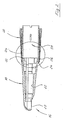
- FIG. 1 is denoted by 10 in total a dental camera handpiece. This is provided via an only schematically indicated cable 12 with an operating unit 14, which provides observation light and supply voltages for the electronic components contained in the camera hand piece 10 (image converter and image processing) and receives and processes the signals provided by the image converter of the camera.
- an operating unit 14 which provides observation light and supply voltages for the electronic components contained in the camera hand piece 10 (image converter and image processing) and receives and processes the signals provided by the image converter of the camera.
- the camera handpiece 10 has a housing, generally designated 16, which is a plastic molded part.
- the housing 16 comprises a front long housing part 18, which roughly has the shape of a slender cone and is stepped on its inner side in order to accommodate different optical components and the image converter in a predetermined position can. These internal working components of the camera are not shown in the drawing for clarity.
- a transparent window 20 of the housing part 18 allows observation in the oral cavity.
- an axial receptacle 22 is provided, in which a light guide (not shown) is recording, which emits light through the window 20 to the observed place.
- the housing part 18 is connected via a conical wall portion 24 with a sleeve-shaped wall portion 26. This has compared to the right of him located wall of the housing part 18 low wall thickness and is thus deformed in the radial inward direction by finger pressure.
- the sleeve-shaped wall section 26 covers the in FIG. 2 right-hand end portion of a support sleeve 28, which also serves to store a coupling sleeve 30 which serves for releasably connecting and locking the handpiece 10 with the correspondingly shaped end of the cable 12.
- the support sleeve 28 in the lying behind the sleeve-shaped wall portion 26 part has a flat circumferential groove 32 which is covered by a film sensor 34.
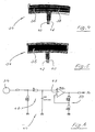
- the film sensor 34 is in the considered embodiment, a piezo film, as described below with reference to the FIGS. 4 and 5 will be described in more detail.
- the geometry of the film sensor 34 is chosen so that it covers the circumferential groove 32 and the adjacent portions of the outer surface of the support sleeve 28 wrinkle-free.
- the circumferential groove 32 adjacent portion of the outer surface of the coupling sleeve 30 has a weak conicity, so that the development of the film sensor 34 corresponds to the development of a truncated cone, that is bounded by two radially spaced circular arcs and two sections of radial rays.
- the film sensor 34 consists of a sensor film 36 and on this printed circuit traces 38.
- the sensor film 36 is made of piezoelectric material and the conductor tracks 38 form the plates of a flat capacitor. If the sensor film 36 is deformed, a voltage is obtained at terminals 40, 42 of the film sensor 34, which is characteristic of the deformation of the sensor film 36.
- the film sensor 34 is a capacitor filled with piezoelectric dielectric and generates a high-impedance output signal ready. To convert this into a low-impedance signal, you can use the in FIG. 6 Inserted signal processing circuit 44 (impedance converter).
- the output from the film sensor 34 voltage is a high-impedance RC filter 46 to the one positive Input of an operational amplifier 48 given. Its output signal is fed back via a voltage divider 50 to the inverting amplifier input.
- the output signal of the operational amplifier 48 is an impedance whose amount corresponds to the deformation of the sensor film 36 and is given to the operating unit 14 for further processing.
- the triggering may cause the operating unit 14, e.g. confirm with an acoustic signal.
Landscapes
- Health & Medical Sciences (AREA)
- Life Sciences & Earth Sciences (AREA)
- Surgery (AREA)
- Biomedical Technology (AREA)
- Medical Informatics (AREA)
- Optics & Photonics (AREA)
- Pathology (AREA)
- Radiology & Medical Imaging (AREA)
- Biophysics (AREA)
- Engineering & Computer Science (AREA)
- Physics & Mathematics (AREA)
- Heart & Thoracic Surgery (AREA)
- Nuclear Medicine, Radiotherapy & Molecular Imaging (AREA)
- Molecular Biology (AREA)
- Animal Behavior & Ethology (AREA)
- General Health & Medical Sciences (AREA)
- Public Health (AREA)
- Veterinary Medicine (AREA)
- Dentistry (AREA)
- Oral & Maxillofacial Surgery (AREA)
- Dental Tools And Instruments Or Auxiliary Dental Instruments (AREA)
- Endoscopes (AREA)
Description
- Die Erfindung betrifft ein dentales Handstück, insbesondere ein intraorales Kamerahandstück gemäß dem Oberbegriff des Anspruches 1.
- Derartige Handstücke sind mit unterschiedlichen internen Arbeitskomponenten bekannt, z. B. Turbinen-Handstücke, Ultraschall-Handstücke, Spray-Handstücke und Kamera-Handstücke.
- Derartige Handstücke beinhalten oft ein Betätigungselement, mit dem das Arbeiten des Handstückes gesteuert wird, z.B. einen Schalter zum Steuern der Sprühflüssigkeit bei einem Spray-Handstück.
- Bei Betätigungselementen von Handstücken besteht immer die Gefahr, daß dort kontaminierte Flüssigkeit in das Innere des Handstückes eindringt. Dieses wird zwar nach jedem Gebrauch sterilisiert oder desinfiziert. Sterilisierung und Sterilisation können aber an solchen Stellen beeinträchtigt sein, die nur schlecht zugänglich sind, z.B. an Spalten. Auch ist für viele Arbeitskomponenten, insbesondere elektronische Komponenten, ein Zutritt von Flüssigkeiten, Feuchtigkeitsnebeln oder feuchter Luft unerwünscht.
- Ein Handstück gemäβ dem Oberbegriff des Anspruchs 1 ist aus
US-2002/049464 bekannt. - Durch die vorliegende Erfindung soll daher ein Handstück gemäß dem Oberbegriff des Anspruches 1 so weitergebildet werden, daß die Betätigungsmöglichkeit einer Arbeitskomponente gegeben ist, ohne daß ein Leckweg zwischen dem Gehäuseinneren und der Umgebung geschaffen wird, und zwar derart, dass eine besonders hohe Empfindlichkeit des Verformungssensors erhalten.
- Diese Aufgabe ist erfindungsgemäß gelöst durch ein Handstück mit dem im Anspruch 1 angegebenen Merkmalen.
- Bei dem erfindungsgemäßen Handstück ist das Gehäuse auch im Bereich der Betätigungseinrichtung absolut durchgehend. Es besteht somit dort keine Gefahr des Eindringens von Verunreinigungen.
- Die Nähe der Betätigungseinrichtung zu der das Handstück führenden Hand erlaubt es, die zu steuernde Arbeitkomponente ergonomisch günstig und bequem ein- und auszuschalten bzw. zu triggern.
- Bei einem erfindungsgemäßen Handstück kann die Betätigung an unterschiedlichen Stellen des ringförmigen Betätigungsabschnittes des Gehäuses erfolgen. Man kann also die Arbeitskomponente in gleicher Weise steuern, ganz gleich, in welcher Winkelorientierung das Handstück gerade gehalten wird.
- Ein erfindungsgemäßes Handstück zeichnet sich auch durch besonders einfachen und robusten Aufbau aus. Falls gewünscht, kann man das analoge Ausgangssignal des Verformungssensors auch zu einer quantitativen Steuerung des Arbeitens einer Arbeitskomponente verwenden, z.B. zum Scharfstellen des Bildes einer Kamera.
- Vorteilhafte Weiterbildungen der Erfindung sind in den Unteransprüchen angegeben.
- Bei einem Handstück gemäß Anspruch 2 kann man das gesamte Gehäuse aus demselben Material herstellen. Die Verformbarkeit des der Betätigungseinrichtung zugeordneten Wandabschnittes des Gehäuses erhält man durch lokale Verkleinerung der Wanddicke.
- Die Weiterbildung der Erfindung gemäß Anspruch 3 ist im Hinblick auf einfache und preisgünstige Herstellung von Vorteil. Kunststoff-Formteile zeichnen sich auch durch gute Oberflächenqualität und ansprechendes Äußeres aus
- Bei einem Handstück gemäß Anspruch 4 kann man mehrere Arbeitskomponenten auf kleinem Raum bequem steuern. Die verschiedenen hinter dem verformbaren Wandabschnitt angeordneten Verformungssensoren können sich bezüglich ihrer Winkelstellung bezogen auf die Achse des Handstückes und/oder bezüglich ihrer axialen Stellung auf dem Handstück unterscheiden.
- Mit der Weiterbildung der Erfindung gemäß Anspruch 6 erhält man ein Handstück, welches bei Betätigung eine Aktion auslösen kann, z.B. das Aufnehmen eines Bildes durch einen Bildwandler einer dentalen intraoralen Kamera.
- Nachstehend wird die Erfindung anhand eines Ausführungsbeispieles unter Bezugnahme auf die Zeichnung näher erläutert. In dieser zeigen:
- Figur 1
- eine seitliche Ansicht eines intraoralen dentalen Kamera-Handstückes;
- Figur 2
- einen axialen Schnitt durch das Gehäuse des in
Figur 1 gezeigten Handstückes; - Figur 3
- eine vergrößerte Ansicht der Anbringung eines Verformungssensorringes auf dem in
Figur 2 gezeigten Gehäuse; - Figur 4
- eine abgewickelte Ansicht eines Piezofolien-Verformungssensors von einer Leiterseite her;
- Figur 5
- eine Aufsicht auf den Piezofolien-Verformungssensors nach
Figur 4 von der entgegengesetzten Seite her; und - Figur 6
- das Schaltbild eines Signalverarbeitungskreises, der in dem in
Figur 1 gezeigten Handstück verwendet wird. - In
Figur 1 ist mit 10 insgesamt ein dentales Kamera-Handstück bezeichnet. Dieses ist über ein nur schematisch angedeutetes Kabel 12 mit einer Betriebseinheit 14 versehen, welche Beobachtungslicht sowie Versorgungsspannungen für die im Kamerahandstück 10 enthaltenen elektronischen Komponenten (Bildwandler und Bildaufbereitung) bereitstellt und die vom Bildwandler der Kamera bereitgestellten Signale entgegennimmt und verarbeitet. - Das Kamerahandstück 10 hat ein insgesamt mit 16 bezeichnetes Gehäuse, welches ein Kunststoff-Spritzteil ist.
- Das Gehäuse 16 umfasst ein vorderes langes Gehäuseteil 18, welches grob die Form eines schlanken Kegels hat und auf seiner Innenseite mehrfach abgestuft ist, um verschiedene optische Komponenten und den Bildwandler in vorgegebener Position aufnehmen zu können. Diese internen Arbeitskomponenten der Kamera sind der Übersichtlichkeit halber in der Zeichnung nicht wiedergegeben. Ein transparentes Fenster 20 des Gehäuseteiles 18 ermöglicht die Beobachtung im Mundraum.
- Im Gehäuseteil 18 ist eine axiale Aufnahme 22 vorgesehen, in welcher ein Lichtleiter (nicht gezeigt) Aufnahme findet, der Licht durch das Fenster 20 an den zu beobachtenden Ort abgibt.
- Im in
Figur 2 links gelegenen Endabschnitt ist das Gehäuseteil 18 über einen konischen Wandabschnitt 24 mit einem hülsenförmigen Wandabschnitt 26 verbunden. Dieser hat verglichen mit der rechts von ihm gelegenen Wand des Gehäuseteiles 18 geringe Wandstärke und ist somit in radialer Einwärtsrichtung durch Fingerdruck verformbar. - Der hülsenförmige Wandabschnitt 26 überdeckt den in
Figur 2 rechts gelegenen Endabschnitt einer Stützhülse 28, die zugleich dazu dient, eine Kupplungshülse 30 zu lagern, die zur lösbaren Verbindung und Verriegelung des Handstückes 10 mit dem entsprechend ausgebildeten Ende des Kabels 12 dient. - Wie insbesondere aus
Figur 3 ersichtlich, hat die Stützhülse 28 in dem hinter dem hülsenförmigen Wandabschnitt 26 liegenden Teil eine flache Umfangsnut 32, die von einer Foliensensor 34 überdeckt wird. - Der Foliensensor 34 ist beim betrachteten Ausführungsbeispiel eine Piezofolie, wie nachstehend unter Bezugnahme auf die
Figuren 4 und 5 noch genauer beschrieben wird. - Die Geometrie des Foliensensors 34 ist so gewählt, daß er die Umfangsnut 32 und die dieser benachbarten Abschnitte der Außenfläche der Stützhülse 28 faltenfrei überdeckt. Beim hier betrachteten Ausführungsbeispiel weist der der Umfangsnut 32 benachbarte Bereich der Außenfläche der Kupplungshülse 30 eine schwache Konizität auf, so daß die Abwicklung des Foliensensors 34 der Abwicklung eines Kegelstumpfes entspricht, also durch zwei radial beabstandete Kreisbögen und zwei Abschnitte radialer Strahlen begrenzt ist.
- Wie aus den
Figuren 4 und 5 ersichtlich, besteht der Foliensensor 34 aus einer Sensorfolie 36 sowie auf diese aufgedruckten Leiterbahnen 38. Die Sensorfolie 36 ist aus piezoelektrischem Material hergestellt und die Leiterbahnen 38 bilden die Platten eines flächigen Kondensators. Wird die Sensorfolie 36 verformt, erhält man an Anschlußklemmen 40, 42 des Foliensensors 34 eine Spannung, die für die Verformung der Sensorfolie 36 charakteristisch ist. - Der Foliensensor 34 stellt einen mit piezoelektrischem Dielektrikum gefüllten Kondensator dar und erzeugt ein hochohmiges Ausgangssignal bereit. Um dieses in ein niederohmiges Signal umszusetzen, kann man den in
Figur 6 gezeigten Signalverarbeitungskreis 44 (Impedanzwandler) einsetzen. - Die vom Foliensensor 34 abgegebene Spannung wird über ein hochohmiges RC-Filter 46 auf den einen positiven Eingang eines Operationsverstärkers 48 gegeben. Dessen Ausgangssignal wird über einen Spannungsteiler 50 auf den invertierenden Verstärkereingang zurückgeführt.
- Das Ausgangssignal des Operationsverstärkers 48 ist eine Impedanz, deren Betrag der Verformung der Sensorfolie 36 entspricht und wird zur Weiterverarbeitung auf die Betriebseiheit 14 gegeben.
- Das oben beschriebene Handstück wird wie folgt verwendet:
- Durch Einschalten der Betriebseinheit 14 wird Licht über das Kabel 12 zum Kamerahandstück 10 geleitet. Dieses Licht tritt über das Fenster 20 aus. Der Zahnarzt bewegt nun die Kamera so, bis er auf einem durch die Betriebseinheit 14 angesteuerten Monitor denjenigen Bereich des Mundraumes sieht, von dem er eine Aufnahme wünscht. Der Zahnarzt betätigt nun den verformbaren Wandabschnitt 26 so stark, bis eine Aufnahme ausgelöst wird. Hierzu kann die Betriebseinheit 14 eine mit dem Ausgangssignal des Signalverarbeitungskreises 44 beaufschlagte Trigger- oder Diskriminatorstufe enthalten.
- Das Auslösen kann die Betriebseinheit 14 z.B. durch ein akustisches Signal bestätigen.
- In Abwandlung des oben beschriebenen Ausführungsbeispieles kann man auch andere die Verformung des Wandabschnittes 26 messende Verformungssensoren verwenden, insbesondere Dehnungsmeßstreifen. Der Signalverarbeitungskreis 44 wird dann entsprechend abgeändert.
Claims (6)
- Dentales Handstück, insbesondere intraorales Kamera-Handstück, mit einem Gehäuse (16), innerhalb dessen mindestens eine Arbeitskomponente angeordnet ist, bei dem das Gehäuse (16) mindestens einen elastisch verformbaren Wandabschnitt (26) aufweist, der mit einem Verformungssensor (34) zusammenarbeitet und sich in Umfangsrichtung erstreckt, wobei der Verformungssensor (34) einen Dehnungsmeßstreifen oder eine Piezofolie umfasst und die Umfangserstreckung des verformbaren Wandabschnittes (26) im wesentlichen 360° beträgt, dadurch gekennzeichnet, dass
der Dehnungsmeßstreifen oder die Piezofolie eine Ausnehmung (32) überdeckt, die auf der Außenseite einer Stützhülse (28) vorgesehen ist und axial mit dem verformbaren Wandabschnitt (26) fluchtet. - Handstück nach Anspruch 1, dadurch gekennzeichnet,
dass der elastisch verformbare Wandabschnitt (26) kleinere Wandstärke aufweist als nicht verformbare Wandabschnitte des Gehäuses (16) und dass das Gehäuse (16) aus einem elastischen Material gefertigt ist. - Handstück nach Anspruch 2, dadurch gekennzeichnet, dass das Gehäuse (16) ein Kunststoff-Formteil ist.
- Handstück nach einem der Ansprüche 1 bis 3, dadurch
gekennzeichnet, dass hinter dem ausgedehnten verformbaren Wandabschnitt (26) mehrere verformungssensoren (34) angeordnet sind. - Handstück nach einem der Ansprüche 1 bis 4, dadurch
gekennzeichnet, dass der Verformungssensor (34) mit einem Signalverarbeitungskreis (44) verbunden ist, der ein Impedanz- und/oder Amplituden- und/oder Frequenzumgesetztes Signal erzeugt. - Handstück nach einem der Anspruche 1 bis 5, dadurch
gekennzeichnet, dass in Abhängigkeit vom Ausgangssignal des Verformungssensors (34) ein Triggerkreis ausgelöst wird.
Applications Claiming Priority (2)
| Application Number | Priority Date | Filing Date | Title |
|---|---|---|---|
| DE102006009177A DE102006009177A1 (de) | 2006-02-24 | 2006-02-24 | Dentales Handstück |
| PCT/EP2007/001469 WO2007098874A1 (de) | 2006-02-24 | 2007-02-21 | Dentales handstück |
Publications (2)
| Publication Number | Publication Date |
|---|---|
| EP1986542A1 EP1986542A1 (de) | 2008-11-05 |
| EP1986542B1 true EP1986542B1 (de) | 2011-10-12 |
Family
ID=38055529
Family Applications (1)
| Application Number | Title | Priority Date | Filing Date |
|---|---|---|---|
| EP07711600A Not-in-force EP1986542B1 (de) | 2006-02-24 | 2007-02-21 | Dentales handstück |
Country Status (7)
| Country | Link |
|---|---|
| EP (1) | EP1986542B1 (de) |
| JP (1) | JP2009527301A (de) |
| CN (1) | CN101389262B (de) |
| AT (1) | ATE527932T1 (de) |
| DE (1) | DE102006009177A1 (de) |
| RU (1) | RU2433780C2 (de) |
| WO (1) | WO2007098874A1 (de) |
Families Citing this family (2)
| Publication number | Priority date | Publication date | Assignee | Title |
|---|---|---|---|---|
| DE102008024817A1 (de) | 2008-05-24 | 2009-11-26 | DüRR DENTAL AG | Kamerahandstück |
| DE102012214473B4 (de) | 2012-08-14 | 2022-01-13 | Sirona Dental Systems Gmbh | Verfahren zur Vermessung eines dentalen Objekts mittels einer dentalen Kamera |
Family Cites Families (7)
| Publication number | Priority date | Publication date | Assignee | Title |
|---|---|---|---|---|
| US3463990A (en) * | 1966-11-28 | 1969-08-26 | Bernard A Ross | Pressure-sensitive electrical control device |
| JP3321212B2 (ja) * | 1992-12-08 | 2002-09-03 | オリンパス光学工業株式会社 | 内視鏡湾曲装置 |
| JPH11192207A (ja) * | 1997-11-07 | 1999-07-21 | Matsushita Electric Ind Co Ltd | ビデオスコープおよび携帯収納ケース |
| US6945981B2 (en) * | 2000-10-20 | 2005-09-20 | Ethicon-Endo Surgery, Inc. | Finger operated switch for controlling a surgical handpiece |
| JP3594943B2 (ja) * | 2002-07-01 | 2004-12-02 | 株式会社長田中央研究所 | 歯科用口腔内観察装置 |
| FR2866799B1 (fr) * | 2004-03-01 | 2006-04-21 | Sopro | Camera a usage medical et notamment dentaire |
| DE102005018047A1 (de) * | 2004-04-19 | 2005-11-17 | Acmi Corp., Southborough | Autoklavierbare Videokamera für ein Endoskop |
-
2006
- 2006-02-24 DE DE102006009177A patent/DE102006009177A1/de not_active Withdrawn
-
2007
- 2007-02-21 AT AT07711600T patent/ATE527932T1/de active
- 2007-02-21 CN CN2007800065659A patent/CN101389262B/zh not_active Expired - Fee Related
- 2007-02-21 RU RU2008137721/14A patent/RU2433780C2/ru not_active IP Right Cessation
- 2007-02-21 JP JP2008555687A patent/JP2009527301A/ja active Pending
- 2007-02-21 EP EP07711600A patent/EP1986542B1/de not_active Not-in-force
- 2007-02-21 WO PCT/EP2007/001469 patent/WO2007098874A1/de not_active Ceased
Also Published As
| Publication number | Publication date |
|---|---|
| WO2007098874A1 (de) | 2007-09-07 |
| EP1986542A1 (de) | 2008-11-05 |
| CN101389262A (zh) | 2009-03-18 |
| CN101389262B (zh) | 2011-02-16 |
| ATE527932T1 (de) | 2011-10-15 |
| DE102006009177A1 (de) | 2007-08-30 |
| JP2009527301A (ja) | 2009-07-30 |
| RU2008137721A (ru) | 2010-03-27 |
| RU2433780C2 (ru) | 2011-11-20 |
Similar Documents
| Publication | Publication Date | Title |
|---|---|---|
| DE10057589C1 (de) | Fußschalter | |
| DE102008047776B4 (de) | Endoskopisches Instrument | |
| DE4028857C2 (de) | ||
| DE102010053814B4 (de) | Endoskop für medizinische Zwecke | |
| DE10013210A1 (de) | Vorrichtung zum Erkennen von Karies, Plaque, bakteriellen Befall, Konkrementen, Zahnstein und anderen fluoreszierenden Substanzen an Zähnen | |
| DE112017005213T5 (de) | Anhebeeinrichtung und Endoskop | |
| DE2636510A1 (de) | Endoskop, insbesondere rektoskop | |
| WO2010121723A1 (de) | Dentale oder medizinische kamera | |
| DE19755169A1 (de) | Periodontaltaschenmeßgerät | |
| DE102007007742A1 (de) | Medizinischer oder chirurgischer Sterilüberzug | |
| EP2015703B1 (de) | Vorrichtung zur montage von kugelköpfen und adapterhülsen als integrierter bestandteil der verpackung | |
| EP1986542A1 (de) | Dentales handstück | |
| DE19948620A1 (de) | Zahnmedizinische Einrichtung | |
| WO2003073952A1 (de) | Zahnärztliches handinstrument | |
| DE102005028215A1 (de) | Vorrichtung für die medizinische Versorgung | |
| DE202007002332U1 (de) | Medizinischer oder chirurgischer Sterilüberzug | |
| EP1321108A1 (de) | Zahnärztliches Arbeitsgerät | |
| EP2862502B1 (de) | Endoskop | |
| DE2724538A1 (de) | Geraet zum automatischen injizieren von fluessigkeiten | |
| DE10343590B4 (de) | Aufsatzvorrichtung für Tattoo- und Permanent-Make-up-Geräte mit Schutzhülle | |
| DE4238977C2 (de) | Vorrichtung zur Beleuchtung und Inspektion von Hohl- und Zwischenräumen | |
| DE8707202U1 (de) | Bestrahlungsgerät | |
| EP0388580A1 (de) | Bildgebendes Aufnahme- und/oder Übertragungsmittel | |
| DE19943474C2 (de) | Pneumatisch-elektrischer Wandler für dentale Einrichtungen | |
| DE69624393T2 (de) | Antrieb für Pumpelemente, insbesondere für Herzunterstützungsvorrichtungen |
Legal Events
| Date | Code | Title | Description |
|---|---|---|---|
| PUAI | Public reference made under article 153(3) epc to a published international application that has entered the european phase |
Free format text: ORIGINAL CODE: 0009012 |
|
| 17P | Request for examination filed |
Effective date: 20080903 |
|
| AK | Designated contracting states |
Kind code of ref document: A1 Designated state(s): AT BE BG CH CY CZ DE DK EE ES FI FR GB GR HU IE IS IT LI LT LU LV MC NL PL PT RO SE SI SK TR |
|
| RAP1 | Party data changed (applicant data changed or rights of an application transferred) |
Owner name: DUERR DENTAL AG |
|
| 17Q | First examination report despatched |
Effective date: 20091109 |
|
| GRAP | Despatch of communication of intention to grant a patent |
Free format text: ORIGINAL CODE: EPIDOSNIGR1 |
|
| DAX | Request for extension of the european patent (deleted) | ||
| GRAS | Grant fee paid |
Free format text: ORIGINAL CODE: EPIDOSNIGR3 |
|
| GRAA | (expected) grant |
Free format text: ORIGINAL CODE: 0009210 |
|
| AK | Designated contracting states |
Kind code of ref document: B1 Designated state(s): AT BE BG CH CY CZ DE DK EE ES FI FR GB GR HU IE IS IT LI LT LU LV MC NL PL PT RO SE SI SK TR |
|
| REG | Reference to a national code |
Ref country code: GB Ref legal event code: FG4D Free format text: NOT ENGLISH |
|
| REG | Reference to a national code |
Ref country code: CH Ref legal event code: EP |
|
| REG | Reference to a national code |
Ref country code: IE Ref legal event code: FG4D |
|
| REG | Reference to a national code |
Ref country code: DE Ref legal event code: R096 Ref document number: 502007008341 Country of ref document: DE Effective date: 20111208 |
|
| REG | Reference to a national code |
Ref country code: NL Ref legal event code: VDEP Effective date: 20111012 |
|
| LTIE | Lt: invalidation of european patent or patent extension |
Effective date: 20111012 |
|
| PG25 | Lapsed in a contracting state [announced via postgrant information from national office to epo] |
Ref country code: IS Free format text: LAPSE BECAUSE OF FAILURE TO SUBMIT A TRANSLATION OF THE DESCRIPTION OR TO PAY THE FEE WITHIN THE PRESCRIBED TIME-LIMIT Effective date: 20120212 Ref country code: LT Free format text: LAPSE BECAUSE OF FAILURE TO SUBMIT A TRANSLATION OF THE DESCRIPTION OR TO PAY THE FEE WITHIN THE PRESCRIBED TIME-LIMIT Effective date: 20111012 |
|
| REG | Reference to a national code |
Ref country code: IE Ref legal event code: FD4D |
|
| PG25 | Lapsed in a contracting state [announced via postgrant information from national office to epo] |
Ref country code: LV Free format text: LAPSE BECAUSE OF FAILURE TO SUBMIT A TRANSLATION OF THE DESCRIPTION OR TO PAY THE FEE WITHIN THE PRESCRIBED TIME-LIMIT Effective date: 20111012 Ref country code: SI Free format text: LAPSE BECAUSE OF FAILURE TO SUBMIT A TRANSLATION OF THE DESCRIPTION OR TO PAY THE FEE WITHIN THE PRESCRIBED TIME-LIMIT Effective date: 20111012 Ref country code: GR Free format text: LAPSE BECAUSE OF FAILURE TO SUBMIT A TRANSLATION OF THE DESCRIPTION OR TO PAY THE FEE WITHIN THE PRESCRIBED TIME-LIMIT Effective date: 20120113 Ref country code: NL Free format text: LAPSE BECAUSE OF FAILURE TO SUBMIT A TRANSLATION OF THE DESCRIPTION OR TO PAY THE FEE WITHIN THE PRESCRIBED TIME-LIMIT Effective date: 20111012 Ref country code: SE Free format text: LAPSE BECAUSE OF FAILURE TO SUBMIT A TRANSLATION OF THE DESCRIPTION OR TO PAY THE FEE WITHIN THE PRESCRIBED TIME-LIMIT Effective date: 20111012 Ref country code: PT Free format text: LAPSE BECAUSE OF FAILURE TO SUBMIT A TRANSLATION OF THE DESCRIPTION OR TO PAY THE FEE WITHIN THE PRESCRIBED TIME-LIMIT Effective date: 20120213 |
|
| PG25 | Lapsed in a contracting state [announced via postgrant information from national office to epo] |
Ref country code: CY Free format text: LAPSE BECAUSE OF FAILURE TO SUBMIT A TRANSLATION OF THE DESCRIPTION OR TO PAY THE FEE WITHIN THE PRESCRIBED TIME-LIMIT Effective date: 20111012 |
|
| PG25 | Lapsed in a contracting state [announced via postgrant information from national office to epo] |
Ref country code: CZ Free format text: LAPSE BECAUSE OF FAILURE TO SUBMIT A TRANSLATION OF THE DESCRIPTION OR TO PAY THE FEE WITHIN THE PRESCRIBED TIME-LIMIT Effective date: 20111012 Ref country code: BG Free format text: LAPSE BECAUSE OF FAILURE TO SUBMIT A TRANSLATION OF THE DESCRIPTION OR TO PAY THE FEE WITHIN THE PRESCRIBED TIME-LIMIT Effective date: 20120112 Ref country code: SK Free format text: LAPSE BECAUSE OF FAILURE TO SUBMIT A TRANSLATION OF THE DESCRIPTION OR TO PAY THE FEE WITHIN THE PRESCRIBED TIME-LIMIT Effective date: 20111012 Ref country code: EE Free format text: LAPSE BECAUSE OF FAILURE TO SUBMIT A TRANSLATION OF THE DESCRIPTION OR TO PAY THE FEE WITHIN THE PRESCRIBED TIME-LIMIT Effective date: 20111012 Ref country code: IE Free format text: LAPSE BECAUSE OF FAILURE TO SUBMIT A TRANSLATION OF THE DESCRIPTION OR TO PAY THE FEE WITHIN THE PRESCRIBED TIME-LIMIT Effective date: 20111012 Ref country code: DK Free format text: LAPSE BECAUSE OF FAILURE TO SUBMIT A TRANSLATION OF THE DESCRIPTION OR TO PAY THE FEE WITHIN THE PRESCRIBED TIME-LIMIT Effective date: 20111012 |
|
| PLBE | No opposition filed within time limit |
Free format text: ORIGINAL CODE: 0009261 |
|
| STAA | Information on the status of an ep patent application or granted ep patent |
Free format text: STATUS: NO OPPOSITION FILED WITHIN TIME LIMIT |
|
| BERE | Be: lapsed |
Owner name: DURR DENTAL A.G. Effective date: 20120228 |
|
| PG25 | Lapsed in a contracting state [announced via postgrant information from national office to epo] |
Ref country code: IT Free format text: LAPSE BECAUSE OF FAILURE TO SUBMIT A TRANSLATION OF THE DESCRIPTION OR TO PAY THE FEE WITHIN THE PRESCRIBED TIME-LIMIT Effective date: 20111012 Ref country code: RO Free format text: LAPSE BECAUSE OF FAILURE TO SUBMIT A TRANSLATION OF THE DESCRIPTION OR TO PAY THE FEE WITHIN THE PRESCRIBED TIME-LIMIT Effective date: 20111012 Ref country code: PL Free format text: LAPSE BECAUSE OF FAILURE TO SUBMIT A TRANSLATION OF THE DESCRIPTION OR TO PAY THE FEE WITHIN THE PRESCRIBED TIME-LIMIT Effective date: 20111012 |
|
| 26N | No opposition filed |
Effective date: 20120713 |
|
| PG25 | Lapsed in a contracting state [announced via postgrant information from national office to epo] |
Ref country code: MC Free format text: LAPSE BECAUSE OF NON-PAYMENT OF DUE FEES Effective date: 20120229 |
|
| REG | Reference to a national code |
Ref country code: CH Ref legal event code: PL |
|
| GBPC | Gb: european patent ceased through non-payment of renewal fee |
Effective date: 20120221 |
|
| PG25 | Lapsed in a contracting state [announced via postgrant information from national office to epo] |
Ref country code: LI Free format text: LAPSE BECAUSE OF NON-PAYMENT OF DUE FEES Effective date: 20120229 Ref country code: CH Free format text: LAPSE BECAUSE OF NON-PAYMENT OF DUE FEES Effective date: 20120229 |
|
| REG | Reference to a national code |
Ref country code: DE Ref legal event code: R097 Ref document number: 502007008341 Country of ref document: DE Effective date: 20120713 |
|
| PG25 | Lapsed in a contracting state [announced via postgrant information from national office to epo] |
Ref country code: BE Free format text: LAPSE BECAUSE OF NON-PAYMENT OF DUE FEES Effective date: 20120228 |
|
| PG25 | Lapsed in a contracting state [announced via postgrant information from national office to epo] |
Ref country code: GB Free format text: LAPSE BECAUSE OF NON-PAYMENT OF DUE FEES Effective date: 20120221 |
|
| REG | Reference to a national code |
Ref country code: AT Ref legal event code: MM01 Ref document number: 527932 Country of ref document: AT Kind code of ref document: T Effective date: 20120221 |
|
| PG25 | Lapsed in a contracting state [announced via postgrant information from national office to epo] |
Ref country code: ES Free format text: LAPSE BECAUSE OF FAILURE TO SUBMIT A TRANSLATION OF THE DESCRIPTION OR TO PAY THE FEE WITHIN THE PRESCRIBED TIME-LIMIT Effective date: 20120123 |
|
| PGFP | Annual fee paid to national office [announced via postgrant information from national office to epo] |
Ref country code: FR Payment date: 20130318 Year of fee payment: 7 |
|
| PG25 | Lapsed in a contracting state [announced via postgrant information from national office to epo] |
Ref country code: AT Free format text: LAPSE BECAUSE OF NON-PAYMENT OF DUE FEES Effective date: 20120221 Ref country code: FI Free format text: LAPSE BECAUSE OF FAILURE TO SUBMIT A TRANSLATION OF THE DESCRIPTION OR TO PAY THE FEE WITHIN THE PRESCRIBED TIME-LIMIT Effective date: 20111012 |
|
| PGFP | Annual fee paid to national office [announced via postgrant information from national office to epo] |
Ref country code: DE Payment date: 20130425 Year of fee payment: 7 |
|
| PG25 | Lapsed in a contracting state [announced via postgrant information from national office to epo] |
Ref country code: TR Free format text: LAPSE BECAUSE OF FAILURE TO SUBMIT A TRANSLATION OF THE DESCRIPTION OR TO PAY THE FEE WITHIN THE PRESCRIBED TIME-LIMIT Effective date: 20111012 |
|
| PG25 | Lapsed in a contracting state [announced via postgrant information from national office to epo] |
Ref country code: LU Free format text: LAPSE BECAUSE OF NON-PAYMENT OF DUE FEES Effective date: 20120221 |
|
| PG25 | Lapsed in a contracting state [announced via postgrant information from national office to epo] |
Ref country code: HU Free format text: LAPSE BECAUSE OF FAILURE TO SUBMIT A TRANSLATION OF THE DESCRIPTION OR TO PAY THE FEE WITHIN THE PRESCRIBED TIME-LIMIT Effective date: 20070221 |
|
| REG | Reference to a national code |
Ref country code: DE Ref legal event code: R119 Ref document number: 502007008341 Country of ref document: DE |
|
| REG | Reference to a national code |
Ref country code: FR Ref legal event code: ST Effective date: 20141031 |
|
| REG | Reference to a national code |
Ref country code: DE Ref legal event code: R119 Ref document number: 502007008341 Country of ref document: DE Effective date: 20140902 |
|
| PG25 | Lapsed in a contracting state [announced via postgrant information from national office to epo] |
Ref country code: DE Free format text: LAPSE BECAUSE OF NON-PAYMENT OF DUE FEES Effective date: 20140902 Ref country code: FR Free format text: LAPSE BECAUSE OF NON-PAYMENT OF DUE FEES Effective date: 20140228 |