EP1986523B1 - Device for maintaining the sliding rail of runners on drawers in an adjustable manner - Google Patents
Device for maintaining the sliding rail of runners on drawers in an adjustable manner Download PDFInfo
- Publication number
- EP1986523B1 EP1986523B1 EP07722890.6A EP07722890A EP1986523B1 EP 1986523 B1 EP1986523 B1 EP 1986523B1 EP 07722890 A EP07722890 A EP 07722890A EP 1986523 B1 EP1986523 B1 EP 1986523B1
- Authority
- EP
- European Patent Office
- Prior art keywords
- lever arm
- running rail
- running
- opening
- drawer
- Prior art date
- Legal status (The legal status is an assumption and is not a legal conclusion. Google has not performed a legal analysis and makes no representation as to the accuracy of the status listed.)
- Active
Links
Images


Classifications
-
- A—HUMAN NECESSITIES
- A47—FURNITURE; DOMESTIC ARTICLES OR APPLIANCES; COFFEE MILLS; SPICE MILLS; SUCTION CLEANERS IN GENERAL
- A47B—TABLES; DESKS; OFFICE FURNITURE; CABINETS; DRAWERS; GENERAL DETAILS OF FURNITURE
- A47B88/00—Drawers for tables, cabinets or like furniture; Guides for drawers
- A47B88/40—Sliding drawers; Slides or guides therefor
- A47B88/423—Fastening devices for slides or guides
- A47B88/427—Fastening devices for slides or guides at drawer side
-
- A—HUMAN NECESSITIES
- A47—FURNITURE; DOMESTIC ARTICLES OR APPLIANCES; COFFEE MILLS; SPICE MILLS; SUCTION CLEANERS IN GENERAL
- A47B—TABLES; DESKS; OFFICE FURNITURE; CABINETS; DRAWERS; GENERAL DETAILS OF FURNITURE
- A47B2210/00—General construction of drawers, guides and guide devices
- A47B2210/0002—Guide construction for drawers
- A47B2210/0051—Guide position
- A47B2210/0054—Adjustment of position of slides
Definitions
- the invention relates to a device for the adjustable support of the rear end of rails of pull-out on the front panel facing away from the inner end of drawers or other extendable in the body of a piece of furniture furniture parts with a rear end of the rail height-adjustable support member arranged by relative displacement of the drawer on the running rail Rail longitudinal device with a rear side provided on the drawer receiving arrangement in the sliding engagement can be brought.
- the holder of the rear inner end of the inner rail of in underfloor arrangement under the bottom of drawers to be arranged drawer pull-out was usually done so that a projecting at one of the top of the running rail combingekanteten leg provided parallel to the top of the track rail retaining lug in a in the drawer rear wall and provided in the rear end portion of the drawer side wall frame opening is inserted.
- This type of holder allows the tool-less assembly and disassembly of the rear drawer end on the track of the associated furniture body pre-assembled extension guides by pushing on or pulling back from the retaining lug. After successful assembly, the drawer is secured in its rear end against lifting secured to the rails.
- a device for adjusting the height of the drawer was developed in the rear end, in which the previously rigidly connected to the running rail retaining lug are adjustable in height direction ( AT 409067B ).
- the invention has for its object to provide a device for height-adjustable mounting of the rear, inner end of the inner rail of the track relative to the drawer, which not only allows easy and quick height adjustment without the use of a tool, but which is also generally suitable, a allow additional lateral displacement of the drawer on the track.
- this object is achieved in that the support member arranged on a perpendicular to the running rail longitudinal axis extending axis in a vertical plane pivotally mounted on the running rail lever arm and attacking on the lever arm on the one hand and on the running rail on the other Height adjustment mechanism is provided.
- the lever arm is mounted in the region of its front panel-side front end at a distance from the rear end facing away from the front panel of the track and its front panel facing away from the end is provided with the support member.
- the receiving arrangement for the height-adjustable support member is provided with advantage in a separately attachable to the drawer back receiving member. This makes it possible to form the support member as projecting from the lever arm approach, which einschieb- in a receiving opening in the receiving member and is retractable from the receiving opening.
- the approach is formed as a substantially planar, laterally projecting from the lever arm plate which einschieb- in the associated slot-shaped receiving opening in the receiving member and is retractable from her.
- configuration is advantageously made so that the flat plate with substantially extending in the longitudinal direction of the lever arm top and bottom laterally from the lever arm and that the slot-shaped receiving opening extends at right angles and parallel to the underside of the drawer bottom, wherein its clear height is dimensioned substantially equal to the thickness of the plate protruding from the lever arm.
- the lateral displacement of the drawer on the track is then possible that the measured perpendicular to the rail longitudinal direction length of the slot-shaped opening is sized larger than the width of the lever arm projecting plate.
- the height adjustment mechanism has an eccentric component which is rotatably mounted on the running rail and is arranged within a slot-like passage opening in the lever arm.
- the slot-like passage opening in the lever arm then extends substantially in the longitudinal direction of the lever arm.
- the eccentric component preferably has a peripheral surface that is axially symmetrical relative to its center axis, wherein the diameter of the eccentric component measured between diametrically opposite regions of the peripheral surfaces is substantially equal to the width of the through opening measured between the opposing longitudinal boundary surfaces of the slot-like passage opening of the lever arm.
- a refinement is expedient in which the eccentric component has a cylindrical peripheral surface in its region located within the passage opening of the lever arm.
- the circumferential surface of the eccentric component can also be formed in its region lying within the passage opening of the lever arm by a multiplicity of consecutive surface areas in the circumferential direction.
- the eccentric member is expedient mounted rotatably about an eccentrically extending to its central axis axis on the running rail.
- a rotary actuating handle may be provided, which preferably has a perpendicular to the central axis of the eccentric radially projecting from this actuating lever.
- the embodiment is made such that the lever arm is provided on its running rail facing away from the surface with a longitudinally displaceable retainer Eraltschiegscardi elongated adjusting slide, which has a relative to the displacement obliquely inclined guide surface arrangement, with which a non-displaceable in the rail longitudinally supported on the running rail control projection cooperates ,
- the guide surface arrangement is then advantageously formed by the oppositely parallel walls of a guide slot extending obliquely to the longitudinal direction of the running rail in the adjusting slide, in which engagement engages a pin portion of the control projection dimensioned in the guide slot in accordance with the slot width.
- the protruding at its end facing the rail from the guide slot end of the pin portion of the control projection expediently fits in a concentric with the pivot axis of the lever arm extending arcuate slot in the lever arm, which allows the pivoting of the lever arm, although the rail side free end of the pin portion rigidly in or on the running rail is attached.
- the elongate adjusting slide is preferably guided in a positionally variable manner in the direction of displacement by two strip-shaped guide elements projecting from its two opposing parallel upper and lower flat sides and projecting from the facing lever flat side.
- the adjusting slide is provided to facilitate its operation on its side facing away from the lever arm side with a vorandden handle.
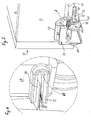
- a rear corner portion of a drawer 10 is shown schematically, of which in the special case of plate-shaped wood material existing rear wall 12, the bottom 14 and a side wall 16 - partially - are shown. How best in FIG. 3 can be seen, a strip-shaped lower edge region of the side wall 16 still occurs over the underside of the grooved into the side wall 16 bottom 14. In this lying below the bottom 16 edge region of the side wall 16, the running rail 18 a - not shown - pull-out arranged, the rear end by height in its entirety designated 20 embodiment of a mounting device according to the invention height and page adjustable on the drawer 10th can be mounted.
- the mounting device 20 has an in FIG. 4 separately above the running rail 18 shown holding member 22 with a flat elongated lever arm 24, which in lateral contact with the in FIG. 4 facing away from the viewer vertical leg surface of the running rail 18 about a perpendicular to the rail longitudinal axis extending axis A pivotally mounted at the rear end of the running rail by means of a - not shown - bearing bore in the running rail 18 protruding from the lever arm 24 projecting bearing pin 24.
- the actual support member 22 is provided in the opposite direction of the journal inner end in the region of the lever arm 24 and formed as projecting from the side facing away from the track substantially flat plate 28.
- a slot-like passage opening 30 is provided, which is aligned substantially in the longitudinal direction of the lever arm.
- the passage opening 30 serves to receive an eccentric component 32 with a relative to its central axis axially symmetrical peripheral surface 34 which either cylindrical or in the in FIG. 4 illustrated manner - may be formed with a plurality of circumferentially successive flats.
- a bearing bore 36 is provided, through which a cylindrical pin portion 38 of a bearing member 40 can be passed, which is provided at its one end with a diameter-enlarged disc-shaped head plate 42.
- a reduced in diameter of the free end face of the pin portion 38 voraturder short pin approach is in a further (not shown) bore in the viewer facing away from the leg surface of the track 18 in a suitable manner - for example by riveting or soldering - fastened.
- the pivotally mounted lever arm 24 In the intended position on the viewer-facing leg surface of the track rail position of the pivotally mounted lever arm 24 thus engages the bearing pin 26 in the associated (not shown) bearing bore.
- Due to the on the planar outer side of an enlarged diameter relative to the eccentric member 32 disk-shaped plate 44 top plate 42 of the eccentric member 32 is held in the intended engagement position in the slot-like through hole 30.
- the lever arm 24 is held in its abutment against the leg surface of the running rail 18, so that a leakage of the bearing pin 26 is prevented from the associated bearing bore with certainty.
- a strip-shaped web 46 is attached, which has at its free end a downward and provided with respect to the mounting rail longitudinal direction with a run-up guide leg 48, which in the intended mounting position on the Outside of the viewer facing leg surface of the rail 18 abuts.
- a run-up guide leg 48 engages in a longitudinal direction in the rail longitudinal direction in the rear end of the web surface of the track rail 18 slot-shaped cutout 50, a complementarily sized strip-shaped projection 51, which is integrally attached to the web surface 46.
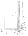
- FIG. 3 is a to be fixed to the drawer rear wall 12, cooperating with the support member described above receiving member 56 not yet mounted on the drawer rear wall, ie shown at a distance in front of the drawer rear wall 12 standing position.
- the trained as a plastic injection molded part receiving member in the illustrated case has an upper elongated horizontally extending mounting portion 58, which can be fastened by means of two in holes 60 in the drawer rear wall 12 technicallypressender mounting pin 62 on the back of the rear wall.
- a receiving plate 64 extending downwards below the level of the underside of the drawer bottom 14 is integrally attached, in which a horizontally extending slit-shaped receiving opening 66 which opens open on the side wall side is formed.
- slot-shaped receiving opening 66 is in the mounting of the drawer in a cabinet body designed as a plate 28 laterally of the pivotable mounted in the running rail 18 lever arm 24 voratder approach of the support member 22 inserted and - at a later disassembly of the drawer of the associated pull-out of the cabinet body - retractable.
- a laterally to the receiving plate 64 offset from the mounting portion 58 downwardly projecting resilient tongue, is used in cooperation with the running rail 18 as tolerance compensation.
- the width of the slot-shaped receiving opening 66 is dimensioned larger than the width of the engaging plate 28 of the support member, so that this plate is therefore displaceable not only in the longitudinal direction of the rails, but also at right angles thereto by a predetermined amount. As a result, a lateral displacement of the drawer10 is possible.
- the plate 28 is provided on its underside with a plurality of extending in rail longitudinal direction Rifflept or locking teeth 70, which cooperates with two associated from the top of the lower boundary surface of the slot-shaped receiving opening 66, also extending in the longitudinal direction rail rails ratchet teeth 72 to prevent unwanted lateral movement of the drawer from a selected side setting in the cabinet body.
- FIGS. 1 . 2 and 5 the drawer is shown in the attached by means of the mounting device 20 according to the invention in the intended mounting position on the running rail 18 position, wherein FIG. 1 illustrates the starting position in which the drawer bottom 14 rests on the upwardly facing web surface of the track rail 18. It can be seen that the gripping plate 54 attached to the free end of the lever 52 of the eccentric component 32 projecting radially from the disk-shaped plate 44 is in this case pivoted into the position facing the rearward end of the running rail 18.
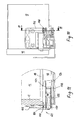
- FIGS. 7 to 11 a second embodiment of a mounting device 120 according to the invention is described, which in the basic structure of the above connection in FIGS. 1 to 6 described holding device 20 corresponds.
- FIGS. 7 to 11 a second embodiment of a mounting device 120 according to the invention is described, which in the basic structure of the above connection in FIGS. 1 to 6 described holding device 20 corresponds.
- In the mounting device of engaging in a through hole 30 in the lever arm eccentric member 32 of the first embodiment is replaced by an elongated adjusting slide 132 which is mounted longitudinally displaceably on the running rail facing away from the flat surface of the lever arm 124.
- This longitudinally displaceable guide is provided by two opposing parallel upper and lower flat sides of the adjusting slide 132 cross projecting from the facing lever flat side strip-shaped guide elements 133.
- In Verstellschieber 132 is a guide surface arrangement in the form of an oblique to the rail longitudinal direction extending through guide slot 130 is provided which of a cylindrical Shank portion 138 of a control projection 140 is penetrated, which passes through the guide carriage 130 and the track side is additionally guided by an arcuate slot 139 in the lever arm 124.
- the free end of the pin portion 138 is riveted in a bore (not shown) in the track rail 18.
- an enlarged diameter head plate 142 is provided, which holds the adjusting slide 132 in the intended mounting position between the strip-shaped guide elements 133.
- a laterally projecting grip plate 154 is provided at its front end facing the drawer front plate.
- the adjusting slide 132 facing upper flat side of the lower guide member 133 occur in cross-section spitzzähnige low locking projections, which cooperate with provided in the zuwandten bottom of the adjusting slide 132 complementary locking receptacles 134.
- the adjusting slide 132 is now so within the predetermined by the length of the guide slot 130 adjustment between the strip-shaped guide elements 133 displaced.
- the embodiment is such that the support member mounted pivotably at the rear end of the mounting rail 18 by turning an Exzenterbauteils or shifting a sliding continuously or finely pivoted and thus a height adjustment of the drawer 10 and further by appropriate design of the sliding connection of the functional component of the support member 22 and the receiving member 56, a lateral displacement of the drawer transversely to the running rail in the longitudinal direction is possible.
Description
Die Erfindung betrifft eine Vorrichtung für die verstellbare Halterung des rückwärtigen Endes von Laufschienen von Ausziehführungen am frontblendenabgewandten inneren Endbereich von Schubladen oder anderen im Korpus eines Möbelstücks ausziehbar gelagerten Möbelteilen mit einem rückwärtigen Ende der Laufschiene höhenverstellbaren angeordneten Halterungselement, welches durch Relativverschiebung der Schublade auf der Laufschiene in Laufschienenlängseinrichtung mit einer rückseitig an der Schublade vorgesehenen Aufnahmeanordnung in den Schiebeeingriff bringbar ist.The invention relates to a device for the adjustable support of the rear end of rails of pull-out on the front panel facing away from the inner end of drawers or other extendable in the body of a piece of furniture furniture parts with a rear end of the rail height-adjustable support member arranged by relative displacement of the drawer on the running rail Rail longitudinal device with a rear side provided on the drawer receiving arrangement in the sliding engagement can be brought.
Die Halterung des rückwärtigen korpusinneren Endes der Laufschiene von in Unterfluranordnung unter dem Boden von Schubladen anzuordnenden Schubladen-Ausziehführungen erfolgte heute in der Regel so, dass eine an einem von der Oberseite der Laufschiene vorspringende hochgekanteten Schenkel vorgesehen parallel zur Oberseite der Laufschiene verlaufende Haltenase in eine in der Schubladen-Rückwand und im rückwärtigen Endbereich der Schubladen-Seitenwandzarge vorgesehenen Öffnung eingeschoben wird. Diese Art der Halterung erlaubt die werkzeuglose Montage und Demontage des rückwärtigen Schubladenendes auf der Laufschiene von im zugehörigen Möbelkorpus vormontierten Ausziehführungen durch Aufschieben auf die bzw. Zurückziehen von der Haltenase. Nach erfolgter Aufschubmontage ist die Schublade in ihrem rückwärtigen Endbereich gegen Abheben gesichert mit den Laufschienen verbunden. Für solche Fälle, in denen eine nachträgliche Veränderung der Neigung der Frontblende einer Schublade ohne Veränderung von deren Höhenlage relativ zum Korpus gefordert wird, wurde eine Vorrichtung zur Verstellung der Höhenlage der Schublade im rückwärtigen Endbereich entwickelt, bei welcher die bisher starr mit der Laufschiene verbundenen Haltenase in Höhenrichtung verstellbar ausgebildet sind (
Der Erfindung liegt die Aufgabe zugrunde, eine Vorrichtung zur höhenverstellbaren Halterung des rückwärtigen, korpusinneren Endes der Laufschiene relativ zur Schublade zu schaffen, welche nicht nur eine einfache und schnelle Höhenverstellung ohne den Einsatz eines Werkzeugs ermöglicht, sondern die darüber hinaus auch grundsätzlich geeignet ist, eine zusätzliche seitliche Verschiebung der Schublade auf der Laufschiene zu ermöglichen.The invention has for its object to provide a device for height-adjustable mounting of the rear, inner end of the inner rail of the track relative to the drawer, which not only allows easy and quick height adjustment without the use of a tool, but which is also generally suitable, a allow additional lateral displacement of the drawer on the track.
Ausgehend von einer Vorrichtung der eingangs erwähnten Art wird diese Aufgabe erfindungsgemäß dadurch gelöst, dass das Halterungselement an einem um eine rechtwinklig zur Laufschienenlängsrichtung horizontal verlaufende Achse in einer senkrechten Ebene verschwenkbar an der Laufschiene gelagerten Hebelarm angeordnet und ein am Hebelarm einerseits und an der Laufschiene andererseits angreifende Höhenverstellmechanismus vorgesehen ist.Starting from a device of the type mentioned above, this object is achieved in that the support member arranged on a perpendicular to the running rail longitudinal axis extending axis in a vertical plane pivotally mounted on the running rail lever arm and attacking on the lever arm on the one hand and on the running rail on the other Height adjustment mechanism is provided.
In bevorzugter Ausgestaltung der Erfindung ist der Hebelarm im Bereich seines frontblendenseitigen vorderen Endes mit Abstand vom rückwärtigen frontblendenabgewandten Ende der Laufschiene gelagert und sein frontblendenabgewandtes Ende ist mit dem Halterungselement versehen.In a preferred embodiment of the invention, the lever arm is mounted in the region of its front panel-side front end at a distance from the rear end facing away from the front panel of the track and its front panel facing away from the end is provided with the support member.
Die Aufnahmeanordnung für das höhenverstellbare Halterungselement ist dabei mit Vorteil in einem gesondert an der Schubladenrückseite anbringbaren Aufnahmebauteil vorgesehen. Dadurch ist es möglich, das Halterungselement als vom Hebelarm vorspringenden Ansatz auszubilden, der in einer Aufnahmeöffnung im Aufnahmebauteil einschieb- und aus der Aufnahmeöffnung zurückziehbar ist. Der Ansatz wird dabei als im Wesentlichen ebenflächige, seitlich vom Hebelarm vorspringende Platte ausgebildet, welche in die zugeordnete schlitzförmige Aufnahmeöffnung im Aufnahmebauteil einschieb- und aus ihr zurückziehbar ist.The receiving arrangement for the height-adjustable support member is provided with advantage in a separately attachable to the drawer back receiving member. This makes it possible to form the support member as projecting from the lever arm approach, which einschieb- in a receiving opening in the receiving member and is retractable from the receiving opening. The approach is formed as a substantially planar, laterally projecting from the lever arm plate which einschieb- in the associated slot-shaped receiving opening in the receiving member and is retractable from her.
Dabei ist Ausgestaltung mit Vorteil so getroffen, dass die ebene Platte mit im Wesentlichen in Längsrichtung des Hebelarms verlaufender Ober- und Unterseite seitlich vom Hebelarm vortritt und dass die schlitzförmige Aufnahmeöffnung rechtwinklig und parallel zur Unterseite des Schubladenbodens verläuft, wobei ihre lichte Höhe im Wesentlichen gleich der Dicke der vom Hebelarm vortretenden Platte bemessen ist.In this case, configuration is advantageously made so that the flat plate with substantially extending in the longitudinal direction of the lever arm top and bottom laterally from the lever arm and that the slot-shaped receiving opening extends at right angles and parallel to the underside of the drawer bottom, wherein its clear height is dimensioned substantially equal to the thickness of the plate protruding from the lever arm.
Die seitliche Verschiebung der Schublade auf der Laufschiene wird dann dadurch möglich, dass die rechtwinklig zur Laufschienenlängsrichtung gemessene Länge der schlitzförmigen Öffnung größer als die Breite der vom Hebelarm vorspringenden Platte bemessen ist.The lateral displacement of the drawer on the track is then possible that the measured perpendicular to the rail longitudinal direction length of the slot-shaped opening is sized larger than the width of the lever arm projecting plate.
Um die Schublade dann in einer getroffenen Seiteneinstellung zu fixieren, ist es von Vorteil, wenn in einer der Flachseiten der vom Hebelarm vorspringenden Platte und der zugeordneten Begrenzungsseite der schlitzförmigen Aufnahmeöffnung in Laufschienenlängsrichtung verlaufende Riffelungen oder Rastverzahnungen vorgesehen sind.In order to then fix the drawer in a struck page setting, it is advantageous if provided in one of the flat sides of the lever arm projecting plate and the associated boundary side of the slot-shaped receiving opening extending in the rail longitudinal corrugations or locking teeth.
Der Höhenverstellmechanismus weist bei einem ersten Ausführungsbeispiel der Erfindung einen innerhalb einer langlochartigen Durchgangsöffnung im Hebelarm angeordneten drehbar an der Laufschiene gelagerten Exzenterbauteil auf. Die langlochartige Durchgangsöffnung im Hebelarm verläuft dann im Wesentlichen in Längsrichtung des Hebelarms.In a first exemplary embodiment of the invention, the height adjustment mechanism has an eccentric component which is rotatably mounted on the running rail and is arranged within a slot-like passage opening in the lever arm. The slot-like passage opening in the lever arm then extends substantially in the longitudinal direction of the lever arm.
Der Exzenterbauteil weist vorzugsweise eine relativ zu seiner Mittelachse axialsymmetrische Umfangsfläche auf, wobei der zwischen diametral gegenüberliegenden Bereichen der Umfangsflächen gemessene Durchmesser des Exzenterbauteils im Wesentlichen gleich der zwischen den gegenüberliegenden Längsbegrenzungsflächen der langlochartigen Durchgangsöffnung des Hebelarms gemessenen Breite der Durchgangsöffnung ist. Zweckmäßig ist eine Ausgestaltung, bei welcher der Exzenterbauteil in seinem innerhalb der Durchgangsöffnung des Hebelarms liegenden Bereich eine zylindrische Umfangsfläche aufweist. Alternativ kann die Umfangsfläche des Exzenterbauteils in dessen innerhalb der Durchgangsöffnung des Hebelarms liegendem Bereich auch von einer Vielzahl von in Umfangsrichtung aufeinander folgende Anflächungen gebildet werden.The eccentric component preferably has a peripheral surface that is axially symmetrical relative to its center axis, wherein the diameter of the eccentric component measured between diametrically opposite regions of the peripheral surfaces is substantially equal to the width of the through opening measured between the opposing longitudinal boundary surfaces of the slot-like passage opening of the lever arm. A refinement is expedient in which the eccentric component has a cylindrical peripheral surface in its region located within the passage opening of the lever arm. Alternatively, the circumferential surface of the eccentric component can also be formed in its region lying within the passage opening of the lever arm by a multiplicity of consecutive surface areas in the circumferential direction.
Um den Hubweg für die Höhenverstellung zur Verfügung zu stellen, ist dann der Exzenterbauteil zweckmäßig um eine exzentrisch zu seiner Mittelachse verlaufende Achse drehbar an der Laufschiene gelagert.In order to provide the stroke for the height adjustment available, then the eccentric member is expedient mounted rotatably about an eccentrically extending to its central axis axis on the running rail.
Auf der der Laufschiene abgewandten Flachseite des Exzenterbauteil kann dann eine Drehbetätigungshandhabe vorgesehen sein, welche bevorzugt einen rechtwinklig zur Mittelachse des Exzenterbauteils radial von diesem vorspringenden Betätigungshebel aufweist.On the side facing away from the running rail flat side of the Exzenterbauteil then a rotary actuating handle may be provided, which preferably has a perpendicular to the central axis of the eccentric radially projecting from this actuating lever.
Am freien Ende des Betätigungshebels kann dann mit Vorteil eine von der der Laufschiene abgewandten Seite vom Betätigungshebel vortretende vergrößerte Griffplatte vorgesehen sein.At the free end of the actuating lever can then be provided by the operating lever protruding enlarged handle plate with advantage a side facing away from the running rail side.
Bei einem alternativen Ausführungsbeispiel ist die Ausgestaltung so getroffen, dass der Hebelarm auf seiner laufschienenabgewandten Fläche mit einem in Laufschienenlängsrichtung verschieblich gehalterten langgestreckten Verstellschieber versehen ist, welcher eine relativ zur Verschiebungsrichtung schräg geneigte Führungsflächenanordnung aufweist, mit welcher ein in Laufschienenlängsrichtung unverschieblich an der Laufschiene gehalterter Steuervorsprung zusammenwirkt.In an alternative embodiment, the embodiment is made such that the lever arm is provided on its running rail facing away from the surface with a longitudinally displaceable retainer Eraltschiegsrichtung elongated adjusting slide, which has a relative to the displacement obliquely inclined guide surface arrangement, with which a non-displaceable in the rail longitudinally supported on the running rail control projection cooperates ,
Die Führungsflächenanordnung wird dann mit Vorteil von den gegenüberliegenden parallel verlaufenden Wandungen eines schräg zur Laufschienen-längsrichtung verlaufend im Verstellschieber vorgesehenen Führungsschlitzes gebildet, in welchen ein im Eingriffsbereich in den Führungsschlitz entsprechend der Schlitzbreite bemessener Zapfenabschnitt des Steuervorsprung eingreift.The guide surface arrangement is then advantageously formed by the oppositely parallel walls of a guide slot extending obliquely to the longitudinal direction of the running rail in the adjusting slide, in which engagement engages a pin portion of the control projection dimensioned in the guide slot in accordance with the slot width.
Das an seinem laufschienenzugewandten Ende aus dem Führungsschlitz vortretende Ende des Zapfenabschnitts des Steuervorsprungs greift zweckmäßig passend in einen konzentrisch zur Schwenkachse des Hebelarms verlaufenden bogenförmigen Schlitz im Hebelarm ein, welcher die Verschwenkung des Hebelarms zulässt, obwohl das laufschienenseitige freie Ende des Zapfenabschnitts starr in bzw. an der Laufschiene befestigt ist.The protruding at its end facing the rail from the guide slot end of the pin portion of the control projection expediently fits in a concentric with the pivot axis of the lever arm extending arcuate slot in the lever arm, which allows the pivoting of the lever arm, although the rail side free end of the pin portion rigidly in or on the running rail is attached.
Der langgestreckte Verstellschieber wird dabei bevorzugt von zwei seine gegenüberliegenden parallelen oberen und unteren Flachseiten passend übergreifenden, von der zugewandten Hebelflachseite vorspringenden leistenförmigen Führungselementen in Verschiebungsrichtung positionsveränderbar geführt.The elongate adjusting slide is preferably guided in a positionally variable manner in the direction of displacement by two strip-shaped guide elements projecting from its two opposing parallel upper and lower flat sides and projecting from the facing lever flat side.
Um eine ungewollte Verstellung einer gewählten angehobenen Position der Schubladerückseite zu verhindern können in der schieberzugewandten Flachseite des unteren leistenförmigen Führungselements und der dieser Flachseite zugewandten unteren Flachseite des Verstellschiebers quer zur Verstellrichtung des Schiebers verlaufende Rastvorsprünge und Rastaufnahmen vorgesehen seinIn order to prevent an unintentional adjustment of a selected raised position of the drawer rear can be provided in the slider-facing flat side of the lower strip-shaped guide member and this flat side facing lower flat side of the adjusting slide extending transversely to the adjustment of the slide locking projections and snap-in receptacles
Der Verstellschieber ist zur Erleichterung seiner Betätigung an seiner vom Hebelarm abgewandten Seite mit einer vortretenden Handhabe versehen.The adjusting slide is provided to facilitate its operation on its side facing away from the lever arm side with a vortretenden handle.
Die Erfindung ist in der folgenden Beschreibung von zwei Ausführungsbeispielen in Verbindung mit der Zeichnung näher erläutert, und zwar zeigt:
- Fig. 1
- eine isometrische Ansicht eines rückwandseitigen Eckbereichs einer Schublade mit einem ersten Ausführungsbeispiel einer in der erfindungsgemäßen Weise ausgebildeten Halterungsvorrichtung für das rückwärtige Ende der zugehörigen Laufschiene einer Ausziehführung in der Halterungsposition, in welcher der Schubladenboden auf der oberen Stegfläche der Laufschiene aufsitzt;
- Fig. 2
- eine der
Fig. 1 entsprechende Ansicht in einer gegenüber der Darstellung gemäßFig. 1 von der Oberseite der Laufschiene in Höhenrichtung angehobenen Position der Schubladen-Rückseite; - Fig. 3
- eine isometrische Ansicht des rückwärtigen Eckbereichs der in den
Fig. 1 und2 dargestellten Schublade und des an der Schubladen-Rückwand zu befestigenden Aufnahmebauteils der Halterungsvorrichtung in mit Abstand vor der Rückwand dargestellter Position; - Fig. 4
- eine isometrische Ansicht des rückwärtigen Endabschnitts einer Laufschiene in einer gegenüber der Darstellungen in den
Fig. 1 und2 gedrehten Positionen und des verschwenkbar an der Laufschiene anbringbaren Halterungselements und der Funktionsteilen des Höhenverstellmechanismus der Halterungsvorrichtung in auseinander gezogener Darstellung; - Fig. 5
- eine Schnittansicht, gesehen in Richtung der Pfeile 5-5 in
Fig. 2 ; - Fig. 6
- eine vergrößerte Darstellung des in
Fig. 2 innerhalb desstrichpunktierten Kreises 6 liegenden Bereichs der Halterungsvorrichtung; - Fig. 7
- eine isometrische Ansicht des rückwandseitigen Bereichs einer Schublade mit einem zweiten Ausführungsbeispiel einer in der erfindungsgemäßen Weise ausgebildeten Haltungsvorrichtung für das rückwärtige Ende der zugehörigen Laufschiene einer Ausziehführung;
- Fig. 8
- den rückwärtigen Endbereich der in
Figur 7 gezeigten Ausziehführung ohne die aufgesetzte Schublade; - Fig. 9
- eine isometrische Ansicht des rückwärtigen Endabschnitts einer Laufschiene in einer gegenüber der Darstellung in den
Figuren 7 und 8 gedrehten Position des verschwenkbar an die Laufschiene anbringbaren Halterungselement und der Funktionsteile des Höhenverstellmechanismus des zweiten Ausführungsbeispiels der Halterungsvorrichtung in auseinander gezogener Darstellung; - Fig. 10
- eine Ansicht des in
Figur 7 gezeigten rückwärtigen Eckbereichs der Schublade mit Blickrichtung in Richtung der Verschiebung der auf der Führungsschiene der Ausziehführung; und - Fig. 11
- eine Schnittansicht gesehen Richtung der Pfeile 11-11 in
Figur 10
- Fig. 1
- an isometric view of a rear wall-side corner portion of a drawer with a first embodiment of a trained in the manner of the invention support device for the rear end of the associated track of a pull-out in the mounting position, in which the drawer bottom is seated on the upper web surface of the track rail;
- Fig. 2
- one of the
Fig. 1 corresponding view in a relation to the illustration according toFig. 1 from the top of the track in the vertical direction raised position of the drawer back; - Fig. 3
- an isometric view of the rear corner of the in the
Fig. 1 and2 Drawer shown and to be attached to the drawer rear wall receiving member of the mounting device in a distance in front of the rear wall position shown; - Fig. 4
- an isometric view of the rear end portion of a running rail in a relation to the Representations in the
Fig. 1 and2 rotated positions and the pivotally mounted on the track rail mount member and the functional parts of the height adjustment mechanism of the mounting device in exploded view; - Fig. 5
- a sectional view, as seen in the direction of arrows 5-5 in
Fig. 2 ; - Fig. 6
- an enlarged view of the in
Fig. 2 within the dash-dottedcircle 6 lying portion of the mounting device; - Fig. 7
- an isometric view of the rear wall portion of a drawer with a second embodiment of a trained in the manner of the invention holding device for the rear end of the associated track rail of a pull-out;
- Fig. 8
- the rear end of the in
FIG. 7 shown pull-out without the attached drawer; - Fig. 9
- an isometric view of the rear end portion of a running rail in a comparison with the representation in the
FIGS. 7 and 8 rotated position of the pivotally attachable to the track rail support member and the functional parts of the height adjustment mechanism of the second embodiment of the support device in exploded view; - Fig. 10
- a view of the in
FIG. 7 shown rear corner of the drawer facing in Direction of displacement on the guide rail of the pull-out guide; and - Fig. 11
- a sectional view seen in the direction of arrows 11-11 in
FIG. 10 ,
In den Zeichnungsfiguren 1, 2, 3 und 5 ist schematisch ein rückwärtiger Eckbereich einer Schublade 10 gezeigt, von welcher die im speziellen Fall aus plattenförmigem Holzwerkstoff bestehende Rückwand 12, der Boden 14 und eine Seitenwand 16 - teilweise - dargestellt sind. Wie am besten in
Die Halterungsvorrichtung 20 weist ein in
Ein im Durchmesser verringerter von der freien Stirnseite des Zapfenabschnitts 38 vortretender kurzer Zapfenansatz ist in einer weiteren (nicht gezeigten) Bohrung in der betrachterabgewandten Schenkelfläche der Laufschiene 18 in geeigneter Weise - beispielsweise durch Vernietung oder Verlötung - befestigbar. In der bestimmungsgemäß auf der betrachterabgewandten Schenkelfläche der Laufschiene anliegenden Position des verschwenkbar gelagerten Hebelarms 24 greift also der Lagerzapfen 26 in die zugeordnete (nicht gezeigte) Lagerbohrung ein. Durch die auf der ebenflächigen Außenseite eines im Durchmesser gegenüber dem Exzenterbauteil 32 vergrößerten scheibenförmigen Platte 44 anliegende Kopfplatte 42 wird der Exzenterbauteil 32 in der bestimmungsgemäßen Eingriffslage in der langlochartigen Durchgangsöffnung 30 gehalten. Gleichzeitig wird auch der Hebelarm 24 in seiner Anlage an der Schenkelfläche der Laufschiene 18 gehalten, so dass also ein Austreten des Lagerzapfens 26 aus der zugehörigen Lagerbohrung mit Sicherheit verhindert wird.A reduced in diameter of the free end face of the
Auf der dem als Platte 28 ausgebildeten Halterungselement 22 gegenüberliegenden Flachseite ist noch ein streifenförmiger Steg 46 angesetzt, der an seinem freien Ende einen abwärts gerichteten und in Bezug auf die Montageschienen-Längsrichtung mit einer Anlaufschräge versehenen Führungsschenkel 48 aufweist, welcher in der bestimmungsgemäßen Montageposition auf der Außenseite der betrachterzugewandten Schenkelfläche der Laufschiene 18 anliegt. Zusätzlich greift in einen in Laufschienen-Längsrichtung in das rückwärtige Ende der Stegfläche der Laufschiene 18 eingestanzten schlitzförmigen Ausschnitt 50 ein komplementär bemessener streifenförmiger Vorsprung 51 ein, welcher an der Stegfläche 46 integral angesetzt ist.On the opposite side formed as a
Von der scheibenförmigen Platte 44 des Exzenterbauteils 32 tritt radial eine als Hebel 52 ausgebildete Drehbetätigungshandhabe vor, an deren freien Ende eine vergrößerte Griffplatte 54 angesetzt ist.Of the disc-shaped
In
Die Breite der schlitzförmigen Aufnahmeöffnung 66 ist größer als die Breite der in sie eingreifenden Platte 28 des Halterungselements bemessen, so dass diese Platte also nicht nur in Laufschienen-Längsrichtung, sondern auch rechtwinklig hierzu um ein vorgegebenes Maß verschieblich ist. Dadurch wird also auch eine seitliche Verschiebung der Schublade10 möglich.The width of the slot-shaped receiving
Wie in
In den
Aus der vorstehenden Beschreibung ergibt sich nunmehr, dass mittels des vorstehend beschriebenen Ausführungsbeispiels der Halterungsvorrichtung 20 sowohl eine Höhenverstellung des rückwärtigen Endes einer Schublade 10 um das Maß der Exzentrizität des Exzenterbauteils 32 als auch eine seitliche Verschiebung der Schublade durch die Möglichkeit der Verschiebung der Platte 28 in der gegenüber dieser länger bemessenen schlitzförmigen Aufnahmeöffnung 66 des Aufnahmebauteils möglich ist.From the above description it follows now that by means of the above-described embodiment of the holding
In den
Bei der Halterungs-Vorrichtung ist der in eine Durchgangsöffnung 30 im Hebelarm eingreifende Exzenter-Bauteil 32 des ersten Ausführungsbeispiels durch einen langgestreckten Verstellschieber 132 ersetzt, welcher auf der laufschienenabgewandten Flachseite der Außenfläche des Hebelarms 124 längsverschieblich gehaltert ist. Diese längsverschiebliche Führung erfolgt durch zwei die gegenüberliegenden parallelen oberen und unteren Flachseiten des Verstellschiebers 132 übergreifende von der zugewandten Hebel-Flachseite vorspringende leistenförmige Führungselemente 133. Im Verstellschieber 132 ist eine Führungsflächenanordnung in Form eines schräg zur Laufschienenlängsrichtung verlaufenden durchgehenden Führungsschlitzes 130 vorgesehen, welcher von einem zylindrischen Schaftabschnitt 138 eines Steuervorsprungs 140 durchsetzt wird, welcher den Führungsschlitten 130 durchgreift und laufschienenseitig zusätzlich durch einen bogenförmigen Schlitz 139 im Hebelarm 124 geführt ist. Das freie Ende des Zapfenabschnitts 138 ist in einer - nicht gezeigten Bohrung - in der Laufschiene 18 vernietet. Am gegenüberliegenden Ende ist eine im Durchmesser vergrößerte Kopfplatte 142 vorgesehen, welche den Verstellschieber 132 in der bestimmungsgemäßen Montagelage zwischen den leistenförmigen Führungselementen 133 hält.In the mounting device of engaging in a through
Als Handhabe zur Verschiebung des Verstellschiebers 132 ist an dessen zur Schubladen-Frontplatte weisenden vorderen Ende eine seitlich vorspringende Griffplatte 154 vorgesehen. Von der dem Verstellschieber 132 zugewandten oberen Flachseite des unteren Führungselements 133 treten im Querschnitt spitzzähnige niedrige Rastvorsprünge vor, welche mit in der zuwandten Unterseite des Verstellschiebers 132 vorgesehenen komplementäre Rastaufnahmen 134 zusammenwirken. Der Verstellschieber 132 ist nun also innerhalb des durch die Länge des Führungsschlitzes 130 vorgegebenen Verstellwegs zwischen den leistenförmigen Führungselementen 133 verschieblich. Durch den schrägen Verlauf des vom laufschienenfesten Zapfenabschnitt 138 durchsetzte Führungsschlitzes 130 wird dabei bei einer Längsverschiebung der Hebelarm 124 und somit das verschwenkbare Halterungselement 122 insgesamt verschwenkt, wodurch die Schublade durch Übertragung der Verschwenkbewegung des Hebelarms 124 über die in die schlitzförmige Aufnahmeöffnung des Aufnahmebauteils 156 eingreifende Platte 128 verschwenkt wird. Der max. Verschwenkweg ist dabei durch den Höhenunterschied zwischen den Enden des Führungsschlitzes 130 vorgegeben.As a handle for the displacement of the adjusting
Es ist ersichtlich, dass im Rahmen des Erfindungsgedankens Abwandlungen und Weiterbildung des beschriebenen Ausführungsbeispiels verwirklichbar sind, welche sich z. B. auf die Befestigung des Aufnahmebauteils 56 an der Schublade beziehen. An Stelle der hier vorgesehenen, in Bohrungen 60 in der Rückwand 12 einpressbaren Befestigungszapfen kann auch eine Schraubverbindung vorgesehen sein, bei welcher der Aufnahmebauteil direkt mit Befestigungsschrauben auf der Rückwand 12 befestigt wird. Die Befestigungszapfen 62 können alternativ auch als nach Art von Spreizdübeln durch Eindrehen von Schrauben aufspreizbare Befestigungszapfen ausgebildet werden. Wesentlich im Rahmen der Erfindung ist die Ausgestaltung derart, dass das verschwenkbar am rückwärtigen Ende der Montageschiene 18 gelagerte Halterungselement durch Verdrehen eines Exzenterbauteils bzw. Verschieben eines Verstellschiebers stufenlos oder feinstufig verschwenkbar und damit eine Höhenverstellung der Schublade 10 und weiterhin durch entsprechende Ausgestaltung der Schiebeverbindung der Funktionsbauteil des Halterungselements 22 und das Aufnahmebauteil 56 ein seitliches Verschieben der Schublade quer zur Laufschiene in Längsrichtung möglich ist.It can be seen that within the scope of the inventive concept modifications and development of the described embodiment can be realized, which is z. B. refer to the attachment of the receiving
Claims (23)
- Device for the adjustable mounting of the rear end of running rails (18) of pull-out guides at the inner end section of drawers (10) facing away from the front panel, or other furniture components mounted in the carcass of a piece of furniture so as to be capable of being pulled out, with a mounting element (22) located with height adjustment facility at the rear end of the running rail (18) and which, through relative movement of the drawers (10) on the running rail (18) in the longitudinal direction of the running rail, may be brought into sliding engagement with a locating assembly provided at the rear of the drawer (10) or the furniture component capable of being pulled out,
characterised in that
the mounting element (22) is arranged on a lever arm (24) mounted so as to be pivotable on the running rail (18) in a vertical plane around an axis (A) running horizontally at right-angles to the running rail longitudinal direction, and a height adjustment mechanism acting at one end on the lever arm (24) and at the other end on the running rail (18) is provided. - Device according to claim 1, characterised in that the lever arm (24) is mounted in the area of its front-panel-side front end with clearance from the rear end of the running rail (18) facing away from the front panel, and its end facing away from the front panel is provided with the mounting element (22).
- Device according to claim 2, characterised in that the locating assembly is provided in a separate locating part (56) which may be attached to the rear of the drawer.
- Device according to claims 2 and 3, characterised in that is in the form of an attachment protruding from the lever arm (24), which may be pushed into and pulled out of a locating opening in the locating part (56).
- Device according to claim 4, characterised in that the attachment has the form of a substantially planar plate (28), protruding sideways from the lever arm (24), which may be pushed into and pulled out of the slotted locating aperture (66) in the locating part (56).
- Device according to claim 5, characterised in that the flat plate (28) extends sideways from the lever arm (24) with top and bottom sides running substantially in the axial direction of the lever arm (24), and that the slotted locating opening (66) runs at right-angles to and parallel to the underside of the drawer bottom (14), wherein its clear height is made substantially equal to the thickness of the plate (28) extending from the lever arm (24).
- Device according to claim 6, characterised in that the length of the slotted opening (66) measured at right-angles to the axial direction of the running rails is greater than the width of the plate (28) protruding from the lever arm (24).
- Device according to claim 7 characterised in that fluting, or engaging teeth (70, 72), running in the axial direction of the running rails are provided in one of the flat sides of the plate protruding from the lever arm (24) and in the assigned edge side of the slotted locating opening (66).
- Device according to any of claims 1 to 8, characterised in that the height adjustment mechanism has an eccentric part (32) fitted within an oblong-hole-shaped through opening (30) in the lever arm (24) and mounted rotatably on the running rail (28).
- Device according to claim 9, characterised in that the oblong-hole-shaped through opening (30) in the lever arm (24) runs substantially in the axial direction of the lever arm (24).
- Device according to claim 9 or 10, characterised in that the eccentric part (32) has a peripheral surface (34) which is axial-symmetric to its centre axis and that the diameter of the eccentric part (30) measured between diametrically opposite sections of the peripheral surface is substantially equal to the width of the through opening (30) measured between the opposite axial boundary surfaces of the oblong-hole-shaped through opening (30) of the lever arm (24).
- Device according to claim 11, characterised in that the eccentric part (32) has a cylindrical peripheral surface (34) in that part of it which lies within the through opening (30) of the lever arm.
- Device according to claim 11, characterised in that the peripheral surface (34) of the eccentric part (32), in that part of it which lies within the through opening (30) of the lever arm (24), is provided with a multiplicity of spot faces, consecutive in the circumferential direction.
- Device according to any of claims 11 to 13, characterised in that the eccentric part (32) is mounted on the running rail (18) so as to be rotatable around an axis eccentric to its centre axis.
- Device according to any of claims 10 to 14, characterised in that a rotary operating handle is provided on the flat side of the eccentric part (32) facing away from the running rail (18).
- Device according to claim 15, characterised in that the rotary operating handle has an operating lever (52) protruding radially from the eccentric part (32) at right-angles to the centre axis of the latter.
- Device according to claim 16, characterised in that the rotary operating handle is provided at the free end of the operating lever (52) and has an enlarged grip plate (54) projecting from the side of the operating lever facing away from the running rail.
- Device according to any of claims 1 to 8, characterised in that the lever arm (124) is provided on its surface facing away from the running rail with an elongated adjusting slide (132) mounted so as to slide in the axial direction of the running rail and which has a guide surface arrangement inclined at an angle relative to the direction of sliding and working in conjunction with a control projection (140) held on the running rail (18) so as to be unable to slide in the axial direction of the running rail.
- Device according to claim 18, characterised in that the guide surface arrangement is formed by the opposite parallel walls of a guide slot (130) provided in the adjusting slide (132) and running at an angle to the axial direction of the running rail and in which a pin section (138) of the control projection (140), dimensioned according to the slot width, engages in the guide slot (130) in the engaging area.
- Device according to claim 19, characterised in that the end of the pin section (138) of the control projection (140) protruding from the guide slot (130) at its end which faces the running rail, engages suitably in a curved slot (139) in the lever arm (124) running concentrically to the pivot axis of the lever arm (124).
- Device according to claim 20, characterised in that the elongated adjusting slide (132) is guided, with the ability to change position in the direction of sliding, by two strip-shaped guide elements (133) suitably overlapping its opposite parallel top and bottom flat sides and protruding from the facing lever flat side.
- Device according to claim 21, characterised in that snap-in projections (135) and snap-in locations (134) running at right-angles to the adjusting direction of the slide are provided in the slide-facing flat side of the bottom strip-shaped guide element (133) and the bottom flat side of the adjusting slide (132) facing this flat side.
- Device according to any of claims 18 to 22, characterised in that the adjusting slide (132) is provided with a protruding handle (154) on its side which faces away from the lever arm (124).
Applications Claiming Priority (2)
| Application Number | Priority Date | Filing Date | Title |
|---|---|---|---|
| DE202006003035U DE202006003035U1 (en) | 2006-02-25 | 2006-02-25 | Device for the adjustable mounting of the running rail of pull-out guides on drawers |
| PCT/EP2007/001514 WO2007096156A2 (en) | 2006-02-25 | 2007-02-22 | Device for maintaining the sliding rail of runners on drawers in an adjustable manner |
Publications (2)
| Publication Number | Publication Date |
|---|---|
| EP1986523A2 EP1986523A2 (en) | 2008-11-05 |
| EP1986523B1 true EP1986523B1 (en) | 2013-05-01 |
Family
ID=38282561
Family Applications (1)
| Application Number | Title | Priority Date | Filing Date |
|---|---|---|---|
| EP07722890.6A Active EP1986523B1 (en) | 2006-02-25 | 2007-02-22 | Device for maintaining the sliding rail of runners on drawers in an adjustable manner |
Country Status (4)
| Country | Link |
|---|---|
| US (1) | US8220884B2 (en) |
| EP (1) | EP1986523B1 (en) |
| DE (1) | DE202006003035U1 (en) |
| WO (1) | WO2007096156A2 (en) |
Cited By (1)
| Publication number | Priority date | Publication date | Assignee | Title |
|---|---|---|---|---|
| DE102019122856A1 (en) * | 2019-08-26 | 2021-03-04 | Paul Hettich Gmbh & Co. Kg | Device for fixing a drawer |
Families Citing this family (39)
| Publication number | Priority date | Publication date | Assignee | Title |
|---|---|---|---|---|
| DE202007014954U1 (en) | 2007-10-31 | 2008-12-18 | Grass Gmbh | Device for attaching a guide unit and furniture part and furniture with such a device |
| DE202008000011U1 (en) * | 2008-02-22 | 2009-04-02 | Elco Kunststoffe Gmbh | Drawer, drawer or the like |
| DE202008011114U1 (en) * | 2008-08-21 | 2010-01-07 | Paul Hettich Gmbh & Co. Kg | Pull-out guide for drawers with a catch hook |
| DE202008013096U1 (en) * | 2008-10-06 | 2010-02-25 | Paul Hettich Gmbh & Co. Kg | Rail of a furniture drawer guide |
| AT508265B1 (en) | 2009-06-10 | 2013-05-15 | Blum Gmbh Julius | EXTRACTION GUIDE FOR DRAWERS |
| AT509416B1 (en) | 2010-02-03 | 2012-05-15 | Blum Gmbh Julius | EXTRACTION GUIDE FOR A DRAWER |
| DE202010012765U1 (en) * | 2010-09-20 | 2012-01-13 | Grass Gmbh | Device for adjusting the inclination of a movable furniture part and furniture |
| DE202010016913U1 (en) * | 2010-12-23 | 2012-03-26 | Grass Gmbh | Furniture with a device for attaching a guide unit |
| TWI411415B (en) * | 2010-12-30 | 2013-10-11 | King Slide Works Co Ltd | Device for adjusting the height of a drawer |
| CN102551379B (en) * | 2010-12-30 | 2014-07-23 | 川湖科技股份有限公司 | Device for adjusting height of drawer |
| US8585165B2 (en) | 2011-01-12 | 2013-11-19 | King Slide Works Co., Ltd. | Device for adjusting height of drawer |
| EP2476340B1 (en) | 2011-01-13 | 2013-03-27 | King Slide Works Co., Ltd. | Device for adjusting the height of a drawer |
| DE202011005570U1 (en) * | 2011-04-21 | 2014-05-26 | Grass Gmbh | Furniture and device for adjusting the inclination of a furniture part |
| AT511418B1 (en) * | 2011-05-05 | 2014-11-15 | Blum Gmbh Julius | EXTRACTION GUIDE FOR A DRAWER |
| EP2706886B1 (en) * | 2011-05-12 | 2015-07-15 | Inter IKEA Systems B.V. | A sliding guide rail |
| ITMI20111454A1 (en) * | 2011-07-29 | 2013-01-30 | Salice Arturo Spa | LOCKING DEVICE FOR FIXING A DRAWER TO A GUIDE |
| ITMI20111628A1 (en) * | 2011-09-08 | 2013-03-09 | Salice Arturo Spa | DEVICE AND METHOD FOR THE SIDE CENTERING OF A DRAWER OR SIMILAR ON AN EXTRACTION GUIDE AND LOCKING DEVICE PROVIDED WITH THE SAME |
| DE102013005512A1 (en) * | 2013-04-02 | 2014-10-02 | Grass Gmbh | Positioning device, apparatus for moving a piece of furniture and furniture and method for mounting a movable furniture part to a guide device |
| DE202013003342U1 (en) * | 2013-04-10 | 2013-06-06 | Kesseböhmer Holding e.K. | Pull-out device for furniture |
| DE102013104829A1 (en) * | 2013-05-10 | 2014-11-13 | Paul Hettich Gmbh & Co. Kg | pull-out guide |
| DE102013114722A1 (en) * | 2013-05-10 | 2014-11-13 | Paul Hettich Gmbh & Co. Kg | Recording unit of a plug connection and plug connection |
| US9101213B2 (en) * | 2013-11-22 | 2015-08-11 | Hardware Resources, Inc. | Undermount drawer slide position adjustment apparatus and method of use |
| US10149539B2 (en) | 2013-11-22 | 2018-12-11 | Hardware Resources, Inc. | Undermount drawer slide position adjustment apparatus and method of use |
| US9986829B2 (en) * | 2013-11-22 | 2018-06-05 | Hardware Resources, Inc. | Undermount drawer slide position adjustment apparatus and method of use |
| DE102014104135B4 (en) * | 2014-03-25 | 2024-01-18 | Paul Hettich Gmbh & Co. Kg | Pull-out guide for a drawer |
| DE102014104136A1 (en) * | 2014-03-25 | 2015-10-01 | Paul Hettich Gmbh & Co. Kg | Pull-out guide for a drawer and method for attaching a drawer to a drawer slide |
| US9066587B1 (en) * | 2014-04-16 | 2015-06-30 | King Slide Works Co., Ltd. | Slide rail system and connecting device used for slide rail assembly |
| DE202014102893U1 (en) | 2014-06-25 | 2015-10-05 | Grass Gmbh | Device for attaching a guide unit to a furniture part |
| CN104622050B (en) * | 2014-12-02 | 2017-04-26 | 广东星徽精密制造股份有限公司 | Removable multi-azimuth slide rail adjusting device |
| CN104490137B (en) * | 2014-12-16 | 2017-02-22 | 伍志勇 | Adjusting mechanism of furniture drawer |
| ES2587433B1 (en) * | 2015-04-21 | 2017-08-01 | Industrias Auxiliares, S.A. | Vertical and horizontal drawer adjustment device |
| US10240632B2 (en) * | 2015-08-06 | 2019-03-26 | Handy Button Machine Co. | Drawer guide system |
| DE202015105679U1 (en) * | 2015-10-26 | 2017-01-27 | Grass Gmbh | Adjusting means for a locking arrangement for adjusting a recorded on a furniture body movable furniture part |
| DE202016104578U1 (en) * | 2016-08-22 | 2016-09-22 | Reme-Möbelbeschläge Gmbh | Pull-out guide for furniture parts |
| TWI605777B (en) * | 2016-12-12 | 2017-11-21 | 川湖科技股份有限公司 | Slide rail mechanism and adjusting assembly for slide rail |
| TWI646922B (en) * | 2017-08-31 | 2019-01-11 | 川湖科技股份有限公司 | Slide rail mechanism and adjusting assembly for slide rail |
| TWI670031B (en) * | 2018-09-27 | 2019-09-01 | 川湖科技股份有限公司 | Slide rail mechanism |
| US10799020B1 (en) * | 2019-05-24 | 2020-10-13 | Rev-A-Shelf Company, Llc | Multi-level cabinet storage system |
| DE102020103955A1 (en) * | 2020-02-14 | 2021-08-19 | Paul Hettich Gmbh & Co. Kg | Fastening device for fixing a push element |
Family Cites Families (13)
| Publication number | Priority date | Publication date | Assignee | Title |
|---|---|---|---|---|
| US2928696A (en) * | 1957-06-19 | 1960-03-15 | Hamilton Mfg Co | Drawer tilt adjustment means |
| DE8228143U1 (en) * | 1982-10-07 | 1983-01-13 | Hagenhenrich Gmbh & Co Kg Metallwarenfabrik, 4837 Verl | UNDERFLOOR EXTENSION GUIDE |
| DE3632442A1 (en) * | 1986-09-24 | 1988-03-31 | Lautenschlaeger Kg Karl | FITTING FOR THE ADJUSTABLE BRACKET OF A DRAWER EXTENSION GUIDE |
| US4842422A (en) * | 1988-08-25 | 1989-06-27 | Nelson Gary W | Eccentric adjuster for drawer or cabinet track |
| AT395099B (en) * | 1989-06-02 | 1992-09-10 | Blum Gmbh Julius | EXTENSION GUIDE SET FOR DRAWERS OR THE LIKE. |
| AT400214B (en) * | 1991-12-06 | 1995-11-27 | Blum Gmbh Julius | DRAWER |
| ES2092209T3 (en) * | 1993-01-12 | 1996-11-16 | Hettich Paul Gmbh & Co | ADJUSTMENT DEVICE FOR THE ORIENTATION OF A DRAWER, SLIDING OR SIMILAR. |
| DE4414462B4 (en) * | 1994-04-26 | 2005-03-24 | MEPLA-WERKE LAUTENSCHLäGER GMBH & CO. KG | Fitting for height adjustment of drawers |
| DE4432820B4 (en) * | 1994-09-15 | 2007-03-22 | MEPLA-WERKE LAUTENSCHLäGER GMBH & CO. KG | Fitting for height adjustment of drawers |
| GB2310997B (en) * | 1996-03-16 | 2000-02-23 | Bernstein Group Plc | A drawer height adjuster |
| AT409067B (en) * | 2000-03-02 | 2002-05-27 | Blum Gmbh Julius | EXTENDING GUIDE FOR DRAWERS |
| DE20107278U1 (en) * | 2001-04-27 | 2001-08-02 | Hettich Paul Gmbh & Co | Device for producing a snap connection |
| TWI249389B (en) * | 2002-06-19 | 2006-02-21 | Salice Arturo Spa | Device for adjusting the height of a drawer |
-
2006
- 2006-02-25 DE DE202006003035U patent/DE202006003035U1/en not_active Expired - Lifetime
-
2007
- 2007-02-22 US US12/280,667 patent/US8220884B2/en active Active
- 2007-02-22 WO PCT/EP2007/001514 patent/WO2007096156A2/en active Search and Examination
- 2007-02-22 EP EP07722890.6A patent/EP1986523B1/en active Active
Cited By (1)
| Publication number | Priority date | Publication date | Assignee | Title |
|---|---|---|---|---|
| DE102019122856A1 (en) * | 2019-08-26 | 2021-03-04 | Paul Hettich Gmbh & Co. Kg | Device for fixing a drawer |
Also Published As
| Publication number | Publication date |
|---|---|
| DE202006003035U1 (en) | 2007-07-05 |
| US8220884B2 (en) | 2012-07-17 |
| US20090167128A1 (en) | 2009-07-02 |
| WO2007096156A2 (en) | 2007-08-30 |
| WO2007096156A3 (en) | 2007-11-29 |
| EP1986523A2 (en) | 2008-11-05 |
Similar Documents
| Publication | Publication Date | Title |
|---|---|---|
| EP1986523B1 (en) | Device for maintaining the sliding rail of runners on drawers in an adjustable manner | |
| EP3125724B1 (en) | Pull-out guide for a drawer | |
| EP2222202B1 (en) | Drawer with front-adjustment | |
| DE202006006065U1 (en) | Underfloor guide arrangement for furniture parts, in particular in the body of furniture | |
| AT512934B1 (en) | drawer | |
| EP1550385A2 (en) | Device for adjusting the height of a drawer | |
| AT509416A1 (en) | EXTRACTION GUIDE FOR A DRAWER | |
| EP0761130A2 (en) | Mounting fitting for drawer front panels | |
| EP1647206A2 (en) | Telescoping slide for a pull-out furniture part | |
| EP3491966A1 (en) | Connecting device and furniture or domestic appliance | |
| EP1256290A1 (en) | Drawer slide for a drawer | |
| AT398516B (en) | DRAWER EXTENSION | |
| EP1421876A1 (en) | Front panel adjustment device for drawers | |
| DE102014104135B4 (en) | Pull-out guide for a drawer | |
| AT515689B1 (en) | drawer | |
| EP2328439A1 (en) | Furniture pull-out guide | |
| EP3189749B1 (en) | Pull-out guide for a movable furniture part | |
| EP0503234A1 (en) | Drawer runner for drawers preferably made of metal | |
| EP1516562B1 (en) | Device for adjusting the inclination of a drawer | |
| EP2618698B1 (en) | Device for adjusting the inclination of a movable furniture part, and piece of furniture | |
| AT395809B (en) | EXTENSION GUIDE FOR DRAWERS AND THE LIKE | |
| DE2821101C3 (en) | Pull-out guide for drawers held in a frame or the like | |
| EP1243203A2 (en) | Fastening system for slides | |
| EP3689184B1 (en) | Device for adjusting a closing position of a drawer, body rail, drawer guide and drawer | |
| AT525094B1 (en) | Device for lateral guidance of the upper end of an extendable piece of furniture |
Legal Events
| Date | Code | Title | Description |
|---|---|---|---|
| PUAI | Public reference made under article 153(3) epc to a published international application that has entered the european phase |
Free format text: ORIGINAL CODE: 0009012 |
|
| 17P | Request for examination filed |
Effective date: 20080530 |
|
| AK | Designated contracting states |
Kind code of ref document: A2 Designated state(s): AT BE BG CH CY CZ DE DK EE ES FI FR GB GR HU IE IS IT LI LT LU LV MC NL PL PT RO SE SI SK TR |
|
| DAX | Request for extension of the european patent (deleted) | ||
| GRAP | Despatch of communication of intention to grant a patent |
Free format text: ORIGINAL CODE: EPIDOSNIGR1 |
|
| GRAS | Grant fee paid |
Free format text: ORIGINAL CODE: EPIDOSNIGR3 |
|
| GRAA | (expected) grant |
Free format text: ORIGINAL CODE: 0009210 |
|
| AK | Designated contracting states |
Kind code of ref document: B1 Designated state(s): AT BE BG CH CY CZ DE DK EE ES FI FR GB GR HU IE IS IT LI LT LU LV MC NL PL PT RO SE SI SK TR |
|
| REG | Reference to a national code |
Ref country code: GB Ref legal event code: FG4D Free format text: NOT ENGLISH |
|
| REG | Reference to a national code |
Ref country code: CH Ref legal event code: EP Ref country code: AT Ref legal event code: REF Ref document number: 609324 Country of ref document: AT Kind code of ref document: T Effective date: 20130515 |
|
| REG | Reference to a national code |
Ref country code: IE Ref legal event code: FG4D Free format text: LANGUAGE OF EP DOCUMENT: GERMAN |
|
| REG | Reference to a national code |
Ref country code: DE Ref legal event code: R096 Ref document number: 502007011696 Country of ref document: DE Effective date: 20130627 |
|
| REG | Reference to a national code |
Ref country code: NL Ref legal event code: VDEP Effective date: 20130501 |
|
| REG | Reference to a national code |
Ref country code: LT Ref legal event code: MG4D |
|
| PG25 | Lapsed in a contracting state [announced via postgrant information from national office to epo] |
Ref country code: ES Free format text: LAPSE BECAUSE OF FAILURE TO SUBMIT A TRANSLATION OF THE DESCRIPTION OR TO PAY THE FEE WITHIN THE PRESCRIBED TIME-LIMIT Effective date: 20130812 Ref country code: IS Free format text: LAPSE BECAUSE OF FAILURE TO SUBMIT A TRANSLATION OF THE DESCRIPTION OR TO PAY THE FEE WITHIN THE PRESCRIBED TIME-LIMIT Effective date: 20130901 Ref country code: SI Free format text: LAPSE BECAUSE OF FAILURE TO SUBMIT A TRANSLATION OF THE DESCRIPTION OR TO PAY THE FEE WITHIN THE PRESCRIBED TIME-LIMIT Effective date: 20130501 Ref country code: SE Free format text: LAPSE BECAUSE OF FAILURE TO SUBMIT A TRANSLATION OF THE DESCRIPTION OR TO PAY THE FEE WITHIN THE PRESCRIBED TIME-LIMIT Effective date: 20130501 Ref country code: GR Free format text: LAPSE BECAUSE OF FAILURE TO SUBMIT A TRANSLATION OF THE DESCRIPTION OR TO PAY THE FEE WITHIN THE PRESCRIBED TIME-LIMIT Effective date: 20130802 Ref country code: FI Free format text: LAPSE BECAUSE OF FAILURE TO SUBMIT A TRANSLATION OF THE DESCRIPTION OR TO PAY THE FEE WITHIN THE PRESCRIBED TIME-LIMIT Effective date: 20130501 Ref country code: LT Free format text: LAPSE BECAUSE OF FAILURE TO SUBMIT A TRANSLATION OF THE DESCRIPTION OR TO PAY THE FEE WITHIN THE PRESCRIBED TIME-LIMIT Effective date: 20130501 Ref country code: PT Free format text: LAPSE BECAUSE OF FAILURE TO SUBMIT A TRANSLATION OF THE DESCRIPTION OR TO PAY THE FEE WITHIN THE PRESCRIBED TIME-LIMIT Effective date: 20130902 |
|
| PG25 | Lapsed in a contracting state [announced via postgrant information from national office to epo] |
Ref country code: PL Free format text: LAPSE BECAUSE OF FAILURE TO SUBMIT A TRANSLATION OF THE DESCRIPTION OR TO PAY THE FEE WITHIN THE PRESCRIBED TIME-LIMIT Effective date: 20130501 Ref country code: BG Free format text: LAPSE BECAUSE OF FAILURE TO SUBMIT A TRANSLATION OF THE DESCRIPTION OR TO PAY THE FEE WITHIN THE PRESCRIBED TIME-LIMIT Effective date: 20130801 Ref country code: CY Free format text: LAPSE BECAUSE OF FAILURE TO SUBMIT A TRANSLATION OF THE DESCRIPTION OR TO PAY THE FEE WITHIN THE PRESCRIBED TIME-LIMIT Effective date: 20130501 |
|
| PG25 | Lapsed in a contracting state [announced via postgrant information from national office to epo] |
Ref country code: LV Free format text: LAPSE BECAUSE OF FAILURE TO SUBMIT A TRANSLATION OF THE DESCRIPTION OR TO PAY THE FEE WITHIN THE PRESCRIBED TIME-LIMIT Effective date: 20130501 |
|
| PG25 | Lapsed in a contracting state [announced via postgrant information from national office to epo] |
Ref country code: CZ Free format text: LAPSE BECAUSE OF FAILURE TO SUBMIT A TRANSLATION OF THE DESCRIPTION OR TO PAY THE FEE WITHIN THE PRESCRIBED TIME-LIMIT Effective date: 20130501 Ref country code: SK Free format text: LAPSE BECAUSE OF FAILURE TO SUBMIT A TRANSLATION OF THE DESCRIPTION OR TO PAY THE FEE WITHIN THE PRESCRIBED TIME-LIMIT Effective date: 20130501 Ref country code: EE Free format text: LAPSE BECAUSE OF FAILURE TO SUBMIT A TRANSLATION OF THE DESCRIPTION OR TO PAY THE FEE WITHIN THE PRESCRIBED TIME-LIMIT Effective date: 20130501 Ref country code: DK Free format text: LAPSE BECAUSE OF FAILURE TO SUBMIT A TRANSLATION OF THE DESCRIPTION OR TO PAY THE FEE WITHIN THE PRESCRIBED TIME-LIMIT Effective date: 20130501 |
|
| PG25 | Lapsed in a contracting state [announced via postgrant information from national office to epo] |
Ref country code: NL Free format text: LAPSE BECAUSE OF FAILURE TO SUBMIT A TRANSLATION OF THE DESCRIPTION OR TO PAY THE FEE WITHIN THE PRESCRIBED TIME-LIMIT Effective date: 20130501 Ref country code: IT Free format text: LAPSE BECAUSE OF FAILURE TO SUBMIT A TRANSLATION OF THE DESCRIPTION OR TO PAY THE FEE WITHIN THE PRESCRIBED TIME-LIMIT Effective date: 20130501 Ref country code: RO Free format text: LAPSE BECAUSE OF FAILURE TO SUBMIT A TRANSLATION OF THE DESCRIPTION OR TO PAY THE FEE WITHIN THE PRESCRIBED TIME-LIMIT Effective date: 20130501 |
|
| PLBE | No opposition filed within time limit |
Free format text: ORIGINAL CODE: 0009261 |
|
| STAA | Information on the status of an ep patent application or granted ep patent |
Free format text: STATUS: NO OPPOSITION FILED WITHIN TIME LIMIT |
|
| 26N | No opposition filed |
Effective date: 20140204 |
|
| REG | Reference to a national code |
Ref country code: DE Ref legal event code: R097 Ref document number: 502007011696 Country of ref document: DE Effective date: 20140204 |
|
| BERE | Be: lapsed |
Owner name: ALFIT AG Effective date: 20140228 |
|
| PG25 | Lapsed in a contracting state [announced via postgrant information from national office to epo] |
Ref country code: LU Free format text: LAPSE BECAUSE OF FAILURE TO SUBMIT A TRANSLATION OF THE DESCRIPTION OR TO PAY THE FEE WITHIN THE PRESCRIBED TIME-LIMIT Effective date: 20140222 Ref country code: MC Free format text: LAPSE BECAUSE OF FAILURE TO SUBMIT A TRANSLATION OF THE DESCRIPTION OR TO PAY THE FEE WITHIN THE PRESCRIBED TIME-LIMIT Effective date: 20130501 |
|
| REG | Reference to a national code |
Ref country code: CH Ref legal event code: PL |
|
| GBPC | Gb: european patent ceased through non-payment of renewal fee |
Effective date: 20140222 |
|
| PG25 | Lapsed in a contracting state [announced via postgrant information from national office to epo] |
Ref country code: CH Free format text: LAPSE BECAUSE OF NON-PAYMENT OF DUE FEES Effective date: 20140228 Ref country code: LI Free format text: LAPSE BECAUSE OF NON-PAYMENT OF DUE FEES Effective date: 20140228 |
|
| REG | Reference to a national code |
Ref country code: FR Ref legal event code: ST Effective date: 20141031 |
|
| REG | Reference to a national code |
Ref country code: IE Ref legal event code: MM4A |
|
| PG25 | Lapsed in a contracting state [announced via postgrant information from national office to epo] |
Ref country code: IE Free format text: LAPSE BECAUSE OF NON-PAYMENT OF DUE FEES Effective date: 20140222 Ref country code: FR Free format text: LAPSE BECAUSE OF NON-PAYMENT OF DUE FEES Effective date: 20140228 Ref country code: GB Free format text: LAPSE BECAUSE OF NON-PAYMENT OF DUE FEES Effective date: 20140222 Ref country code: BE Free format text: LAPSE BECAUSE OF NON-PAYMENT OF DUE FEES Effective date: 20140228 |
|
| PG25 | Lapsed in a contracting state [announced via postgrant information from national office to epo] |
Ref country code: HU Free format text: LAPSE BECAUSE OF FAILURE TO SUBMIT A TRANSLATION OF THE DESCRIPTION OR TO PAY THE FEE WITHIN THE PRESCRIBED TIME-LIMIT; INVALID AB INITIO Effective date: 20070222 Ref country code: TR Free format text: LAPSE BECAUSE OF FAILURE TO SUBMIT A TRANSLATION OF THE DESCRIPTION OR TO PAY THE FEE WITHIN THE PRESCRIBED TIME-LIMIT Effective date: 20130501 |
|
| REG | Reference to a national code |
Ref country code: DE Ref legal event code: R079 Ref document number: 502007011696 Country of ref document: DE Free format text: PREVIOUS MAIN CLASS: A47B0088040000 Ipc: A47B0088400000 |
|
| PGFP | Annual fee paid to national office [announced via postgrant information from national office to epo] |
Ref country code: AT Payment date: 20180219 Year of fee payment: 12 |
|
| REG | Reference to a national code |
Ref country code: AT Ref legal event code: MM01 Ref document number: 609324 Country of ref document: AT Kind code of ref document: T Effective date: 20190222 |
|
| PG25 | Lapsed in a contracting state [announced via postgrant information from national office to epo] |
Ref country code: AT Free format text: LAPSE BECAUSE OF NON-PAYMENT OF DUE FEES Effective date: 20190222 |
|
| PGFP | Annual fee paid to national office [announced via postgrant information from national office to epo] |
Ref country code: DE Payment date: 20230105 Year of fee payment: 17 |
|
| P01 | Opt-out of the competence of the unified patent court (upc) registered |
Effective date: 20230519 |