EP1986266B1 - Système repeteur à antenne transparente intégrée dans une vitre - Google Patents
Système repeteur à antenne transparente intégrée dans une vitre Download PDFInfo
- Publication number
- EP1986266B1 EP1986266B1 EP08155151.7A EP08155151A EP1986266B1 EP 1986266 B1 EP1986266 B1 EP 1986266B1 EP 08155151 A EP08155151 A EP 08155151A EP 1986266 B1 EP1986266 B1 EP 1986266B1
- Authority
- EP
- European Patent Office
- Prior art keywords
- antenna
- construction element
- panel
- element according
- optically transparent
- Prior art date
- Legal status (The legal status is an assumption and is not a legal conclusion. Google has not performed a legal analysis and makes no representation as to the accuracy of the status listed.)
- Active
Links
Images
Classifications
-
- H—ELECTRICITY
- H01—ELECTRIC ELEMENTS
- H01Q—ANTENNAS, i.e. RADIO AERIALS
- H01Q1/00—Details of, or arrangements associated with, antennas
- H01Q1/007—Details of, or arrangements associated with, antennas specially adapted for indoor communication
-
- H—ELECTRICITY
- H01—ELECTRIC ELEMENTS
- H01Q—ANTENNAS, i.e. RADIO AERIALS
- H01Q1/00—Details of, or arrangements associated with, antennas
- H01Q1/12—Supports; Mounting means
- H01Q1/1271—Supports; Mounting means for mounting on windscreens
-
- H—ELECTRICITY
- H01—ELECTRIC ELEMENTS
- H01Q—ANTENNAS, i.e. RADIO AERIALS
- H01Q1/00—Details of, or arrangements associated with, antennas
- H01Q1/44—Details of, or arrangements associated with, antennas using equipment having another main function to serve additionally as an antenna, e.g. means for giving an antenna an aesthetic aspect
-
- H—ELECTRICITY
- H04—ELECTRIC COMMUNICATION TECHNIQUE
- H04B—TRANSMISSION
- H04B7/00—Radio transmission systems, i.e. using radiation field
- H04B7/14—Relay systems
- H04B7/15—Active relay systems
-
- H—ELECTRICITY
- H04—ELECTRIC COMMUNICATION TECHNIQUE
- H04B—TRANSMISSION
- H04B7/00—Radio transmission systems, i.e. using radiation field
- H04B7/14—Relay systems
- H04B7/15—Active relay systems
- H04B7/155—Ground-based stations
- H04B7/15528—Control of operation parameters of a relay station to exploit the physical medium
Definitions
- the field of the invention is that of repeater systems used to relay exchanges between a base station of a mobile telecommunications network and a user terminal.
- Such systems are typically used to provide coverage of the mobile telecommunications network in areas poorly covered by the base stations of the network. These include the interior of buildings in which the electric fields from exterior base stations are strongly attenuated. As a result, network users present inside such buildings are sometimes unable to use network services (for example to receive and make calls).
- the document WO02/095866 discloses a repeater system that includes an antenna disposed inside a building and an antenna disposed outside a building.
- the aim of the invention is to reduce these constraints in the installation of a repeater system, and aims in particular to propose a compact system whose integration into a building is simplified.
- the invention proposes a window-like building element comprising a repeater system according to claim 1.
- the invention relates to a repeater system for relaying exchanges between a base station of a mobile telecommunications network and a user terminal.
- such a repeater system 1 makes it possible to retransmit to the internal antenna 30 (possibly after amplification or regeneration) the signal picked up by the external antenna 10 originating from a base station. This allows this signal to pass inside an enclosed space, intended in particular for a user terminal.
- a retransmitter system 1 makes it possible to retransmit to the external antenna 10 (possibly after amplification or regeneration) the signal picked up by the internal antenna 30 coming from a user terminal located inside the 'Closed space. The signal can then be retransmitted to a base station of the network.
- the external antenna 10 is an optically transparent planar antenna integrated into an optically transparent panel 2 serving for the interior lighting of a space.
- the space whose panel 2 is used for interior lighting is typically a space of the building, automobile or railway vehicle, etc. type.
- the panel 2 typically forms part of a window-type construction element, of which it constitutes what is commonly designated by the term “window”.
- the external antenna 10 is a planar antenna of the printed antenna type.
- the antenna 10 comprises a ground plane 11, a radiation plane 12 in the form of one or more radiating elements 12-15 (these elements, also called patches, are of course not limited to the number of four), and a dielectric substrate interposed between the ground plane 11 and the radiation plane 12.
- Part 3 of panel 2 is used to form the dielectric substrate of the external antenna, so that the external antenna 10 is integrated into panel 2.
- part 3 of panel 2 can be a physical layer of panel 2, for example a layer of glass, or else a layer of void, for example when panel 2 is a structure of the double-glazed type.
- ground plane 11 and the radiation plane 12 can be sandwiched between optically transparent dielectric layers 4, 5 of the panel 2, so as to obtain the stacked structures represented on the figure 3 , 4a and 4b .
- Layer 5 faces the interior of the building, while Layer 4 faces the exterior of the building. Layer 5 thus supports ground plane 11 of the external antenna, while layer 4 covers radiation plane 12 of the external antenna.
- Panel 2 is typically made of glass.
- the panel 2 can however be formed from any other optically transparent dielectric material, for example Plexiglas.
- the panel 2 can be made up of layers of a different nature.
- athermal glass comprising, as we have seen, a radio-electrically opaque metallized layer
- a radio glass electrically transparent for the layer 4 so as to guarantee the free radiation of the external antenna towards the outside.
- the ground plane 11 and the radiating element(s) 12-15 of the radiation plane 12 are each formed by depositing an optically transparent conductive material on a plastic film, for example on a polyester film.
- the optically transparent conductive material can also be directly deposited on the panel by etching processes.
- part 3 of panel 2 serving as a dielectric substrate interposed between radiating element 12 and ground plane 11 has a thickness of 6 mm.
- the layers 4, 5 of the panel sandwiching the radiating element 12/dielectric substrate 3/ground plane 11 structure each have a thickness of 3 mm. These thicknesses are of course provided purely as an indication.
- conductive material is understood to mean a substantially conductive material having a resistivity of less than 10 ohm/square, preferably less than 5 ohm/square.
- Optically transparent material is also understood to mean a material that is substantially transparent to visible light, allowing at least approximately 30% of this light to pass, and preferably more than 60% of the light.
- the optically transparent conductive material is preferably, but not limited to, indium tin oxide (ITO), silver-doped tin oxide (AgHT), or any other metallic material. It will be noted that the AgHT material is a transparent material having a resistivity of the order of 4 ohm/square.
- radioelectric losses being directly linked to the resistivity of the material, it is proposed within the framework of a preferred embodiment of the invention to reduce the losses of the external antenna, and consequently to optimize its gain, favoring the use of square-shaped radiating elements (whose resistivity has in particular been verified to be lower than that of a rectangular radiating element).
- the radiation plane 12 of the external antenna 10 is placed on the side of the panel which is directed towards the outside of the building.
- the power supply to the radiating element(s) 12-15 of the external antenna 10 can be provided by a coaxial probe 16.
- the core of the coaxial probe emerges alone from an opening made in the ground plane 11 and excites the external antenna by direct contact on the edge of the radiation plane 12, or (as shown in the figure 4a ) by electromagnetic coupling using a section (extension of the central core) inwards and parallel to the radiation plane.
- coaxial probe power supply any power supply circuit of a radiating element or of a network of radiating elements consisting of cables coaxial terminated by one or more coaxial excitation probes of the radiating element(s).
- the power supply to the radiating element(s) of the external antenna can be achieved using a micro-strip line 17.
- a line 17 made of AgHT or ITO, and of width much less than the dimension of the antenna is used to bring the energy directly on the edge of the external antenna and thus to feed it.
- This line 17 is placed in the same plane as the radiation plane 12.
- the panel 12 is part of a window-type construction element having an opaque frame 6, and the antenna feed means are arranged in the frame 6.
- the arrangement of the supply means 16 - in particular when it is a question of supply means in the form of a micro-strip line 17 - in the opaque frame proves to be efficient from the radioelectric point of view.
- a feed line printed on a dielectric substrate actually has low losses, which in particular favors the gain of the antenna.
- the feed line can also be designed on a transparent material.
- induced losses due to the material, the lengths of the lines, and above all the rectangular shapes of the tree structure of the line for the supply of several radiating elements; this tree structure is represented on the figures 1 and 2 ) currently lead to lower performance with respect to the gain of the antenna array.
- an external antenna according to the invention fed by a coaxial probe makes it possible to obtain a reflection coefficient of less than ⁇ 10 dB over the entire GSM band.
- the measured gain is close to -3.5 dBi.
- An antenna operating at the same frequency and fed by a printed microstrip line has a gain of about -12 dBi, that is a gain of about -8.5 dB below the gain of the antenna fed by coaxial probe. This discrepancy is attributable to the losses coming from the micro-strip line supplying the antenna.
- the invention offers the advantage of being able to adapt to different window structures.
- checkered window has the advantage of allowing the integration of a relatively large number of radiating elements, in particular when the supply means are integrated into the window jambs.
- the target size for the external antenna is that of an ordinary window, ie a height ranging from 1 m to 1.5 m.
- the internal antenna 30 and the retransmitter means 20 are conventional elements, preferably of small size, which are integrated into the frame 6 of the window.
- the internal antenna 30 can thus be a “dipole” type antenna integrated into the amount of the window.
- the internal antenna 30 can however be made in a manner similar to the external antenna 10, by providing a planar antenna integrated into the panel 2.
- the radiating element(s) (S) of the internal antenna 30 are arranged on the side of the panel which is directed towards the interior of the building.
- the retransmitter means 20 are of the "micro-repeater” device type, with selective band operating in the band of the operator of the mobile telecommunications network by type of band: GSM, DCS or UMTS and by bandwidth (channels concerned).
- micro-repeater device that can be used in the E-GSM band to form the retransmitting means 20 of the invention is the RF repeater system MR 303B EGSM from the company MIKOM.
- the internal antenna is offset from the panel by providing an output connector after the retransmitter means 20.
- Such an embodiment proves to be advantageous in the case where the space to be covered electrically by radio is in the immediate vicinity of the panel 2.
- the retransmitting means are offset from the panel by providing an output connector after the external antenna. This embodiment proves particularly advantageous in the case of window frames that are too cramped to house said retransmitter means therein.
- the invention is not limited to a repeater system as described previously, but also extends to a window-type construction element in which a system according to the first aspect of the invention is integrated.
Landscapes
- Engineering & Computer Science (AREA)
- Computer Networks & Wireless Communication (AREA)
- Signal Processing (AREA)
- Radio Relay Systems (AREA)
- Mobile Radio Communication Systems (AREA)
- Details Of Aerials (AREA)
Description
- Le domaine de l'invention est celui des systèmes répéteur utilisés pour relayer les échanges entre une station de base d'un réseau de télécommunication mobile et un terminal d'usager.
- De tels systèmes sont typiquement utilisés pour assurer une couverture du réseau de télécommunication mobile dans des zones mal couvertes par les stations de base du réseau. Il s'agit notamment de l'intérieur de bâtiments dans lesquels les champs électriques en provenance de stations de base extérieures sont fortement atténués. Il en découle que les usagers du réseau présents à l'intérieur de tels bâtiments se trouvent parfois dans l'incapacité d'utiliser les services du réseau (par exemple pour recevoir et émettre des appels).
- On relèvera en particulier le cas des bâtiments modernes qui font appel à des verres athermiques. Ce type de verre possède effectivement une couche métallisée qui atténue fortement le signal envoyé par la station de base vers les terminaux à l'intérieur du bâtiment, et réciproquement le signal envoyé par les terminaux vers la station de base. Le document
WO02/095866 - Un système répéteur comporte typiquement :
- une antenne positionnée à l'extérieur du bâtiment, apte à communiquer avec une station de base du réseau,
- une antenne positionnée à l'intérieur du bâtiment, apte à communiquer avec un terminal d'usager,
- des moyens réémetteurs prévus pour faire l'interface entre les antennes, en réémettant (avec possibilité d'amplification et de régénération) les signaux reçus par l'une des antennes à destination de l'autre antenne.
- On comprend qu'un tel système répéteur permet d'étendre la couverture réseau à l'intérieur du bâtiment, de sorte que les usagers situés à l'intérieur du bâtiment peuvent bénéficier d'une bonne couverture réseau.
- Lors de la mise en place d'un tel système répéteur, diverses difficultés apparaissent toutefois notamment du fait de l'installation de l'antenne extérieure sur le bâtiment, de l'installation de l'antenne intérieure dans le bâtiment (typiquement sur les murs ou plafonds), ou encore de l'installation des câbles coaxiaux reliant les différents composants du système.
- L'invention a pour objectif de réduire ces contraintes dans l'installation d'un système répéteur, et vise notamment à proposer un système compact dont l'intégration à un bâtiment est simplifiée.
- A cet effet, l'invention propose un élément de construction de type fenêtre comprenant un système répéteur selon la revendication 1.
- Certains aspects préférés, mais non limitatifs, de ce système sont définis dans les revendications dépendantes.
- D'autres aspects, buts et avantages de la présente invention apparaîtront mieux à la lecture de la description détaillée suivante de formes de réalisation préférées de celle-ci, donnée à titre d'exemple non limitatif, et faite en référence aux dessins annexés sur lesquels :
- la
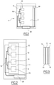
figure 1 est un schéma représentant un système répéteur selon un mode de réalisation possible de l'invention ; - la
figure 2 est un schéma représentant les différents composants d'une antenne externe selon un mode de réalisation possible de l'invention ; - la
figure 3 est une vue en coupe schématique d'une antenne externe selon un mode de réalisation possible de l'invention ; - les
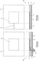
figures 4a et 4b illustrent différents modes de réalisation possible de l'alimentation d'une antenne externe conforme à l'invention ; - les
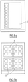
figures 5a et 5b illustrent l'intégration du système selon l'invention dans différents éléments de construction de type fenêtre. - Selon un premier aspect, l'invention concerne un système répéteur pour relayer les échanges entre une station de base d'un réseau de télécommunication mobile et un terminal d'usager.
- En référence à la
figure 1 , le système répéteur 1 comporte - une antenne externe 10 apte à communiquer avec une station de base (non représentée) d'un réseau de télécommunications mobiles ;
- et des moyens réémetteurs 20 reliés à l'antenne externe 10, les moyens réémetteurs 20 étant destinés à faire l'interface entre l'antenne externe 10 et une antenne interne 30 apte à communiquer avec le terminal d'un usager du réseau de télécommunication, pour réémettre les signaux reçus par l'une ou l'autre des antennes à destination de l'autre antenne.
- On comprend qu'un tel système répéteur 1 permet de réémettre à destination de l'antenne interne 30 (éventuellement après amplification ou régénération) le signal capté par l'antenne externe 10 en provenance d'une station de base. Ceci permet de faire transiter ce signal à l'intérieur d'un espace clos, à destination notamment d'un terminal d'usager. Similairement, un tel système réémetteur 1 permet de réémettre à destination de l'antenne externe 10 (éventuellement après amplification ou régénération) le signal capté par l'antenne interne 30 en provenance d'un terminal d'usager situé à l'intérieur de l'espace clos. Le signal peut alors être réémis à destination d'une station de base du réseau.
- Dans le cadre de l'invention, l'antenne externe 10 est une antenne planaire optiquement transparente intégrée à un panneau 2 optiquement transparent servant à l'éclairage intérieur d'un espace.
- L'espace dont le panneau 2 sert à l'éclairage intérieur est typiquement un espace du type bâtiment, véhicule automobile ou ferroviaire, etc.
- On prendra dans la suite de la description l'exemple d'un bâtiment. On comprendra cependant que l'invention n'est pas limitée à cet exemple, mais s'étend à tout espace pour lequel l'éclairage intérieur est assuré à l'aide d'un panneau optiquement transparent.
- Le panneau 2 fait typiquement partie d'un élément de construction de type fenêtre, dont il constitue ce qui est communément désigné par le terme de « vitre ».
- Selon un mode de réalisation possible de l'invention représenté sur les
figures 2, 3 ,4a et 4b , l'antenne externe 10 est une antenne planaire de type antenne imprimée. L'antenne 10 comporte un plan de masse 11, un plan de rayonnement 12 sous la forme d'un ou plusieurs éléments rayonnants 12-15 (ces éléments, dits également patchs, n'étant bien entendu pas limités au nombre de quatre), et un substrat diélectrique interposé entre le plan de masse 11 et le plan de rayonnement 12. - Une partie 3 du panneau 2 est utilisée pour former le substrat diélectrique de l'antenne externe, de sorte que l'antenne externe 10 est intégrée dans le panneau 2.
- On notera ici que la partie 3 du panneau 2 peut être une couche physique du panneau 2, par exemple une couche de verre, ou encore une couche de vide, par exemple lorsque le panneau 2 est une structure du type à double vitrage.
- Par ailleurs, le plan de masse 11 et le plan de rayonnement 12 peuvent être pris en sandwich entre des couches 4, 5 diélectriques optiquement transparentes du panneau 2, de manière à obtenir les structures empilées représentées sur les
figures 3 ,4a et 4b . - La couche 5 donne vers l'intérieur du bâtiment, tandis que la couche 4 donne vers l'extérieur du bâtiment. La couche 5 supporte ainsi le plan de masse 11 de l'antenne externe, tandis que la couche 4 recouvre le plan de rayonnement 12 de l'antenne externe.
- Le panneau 2 est typiquement en verre. Le panneau 2 peut toutefois être formé de tout autre matériau diélectrique optiquement transparent, par exemple en plexiglas.
- On relèvera ici que le panneau 2 peut être constitué de couche de nature différente. On peut en particulier prévoir d'utiliser du verre athermique (comprenant comme on l'a vu une couche métallisée radio électriquement opaque) pour la couche 5 supportant le plan de masse 11 (ce qui permettra en outre de renforcer le blindage du plan de masse), et un verre radio électriquement transparent pour la couche 4 de manière à garantir le rayonnement libre de l'antenne externe vers l'extérieur.
- Le plan de masse 11 et le ou les éléments rayonnants 12-15 du plan de rayonnement 12 sont chacun formés par dépôt d'un matériau conducteur optiquement transparent sur un film plastique, par exemple sur un film en polyester. Le matériau conducteur optiquement transparent peut également être directement déposé sur le panneau par des procédés de gravure.
- Il s'agit typiquement d'un dépôt métallique de très faible épaisseur, de l'ordre de quelques microns.
- En référence au mode de réalisation de la
figure 3 , la partie 3 du panneau 2 servant de substrat diélectrique intercalée entre l'élément rayonnant 12 et le plan de masse 11 présente une épaisseur de 6 mm. Les couches 4, 5 du panneau venant prendre en sandwich la structure élément rayonnant 12/substrat diélectrique 3/plan de masse 11 présentent chacune une épaisseur de 3 mm. Ces épaisseurs sont bien entendu fournies à titre purement indicatif. - Dans le cadre de l'invention, on entend par matériau « conducteur », un matériau substantiellement conducteur présentant une résistivité inférieure à 10 ohm/carré, de préférence inférieure à 5 ohm/carré.
- On entend par ailleurs par matériau « optiquement transparent », un matériau substantiellement transparent à la lumière visible, laissant passer au moins environ 30% de cette lumière, et de préférence plus de 60% de la lumière.
- Le matériau conducteur optiquement transparent est de préférence, sans pour autant que cela ne soit limitatif, de l'oxyde d'indium-étain (ITO), de l'oxyde d'étain dopé à l'argent (AgHT), ou tout autre matériau métallique. On relèvera que le matériau AgHT est un matériau transparent présentant une résistivité de l'ordre de 4 ohm/carré.
- Les pertes radioélectriques étant directement liées à la résistivité du matériau, on propose dans le cadre d'un mode de réalisation préférentiel de l'invention de réduire les pertes de l'antenne externe, et par conséquent d'optimiser son gain, en privilégiant l'utilisation d'éléments rayonnants de forme carré (dont on a pu en particulier vérifier que la résistivité est inférieure à celle d'un élément rayonnent rectangulaire).
- Bien entendu, lorsque le panneau 2 constitue la vitre d'une fenêtre de bâtiment, le plan de rayonnement 12 de l'antenne externe 10 est disposé du côté du panneau qui est dirigé vers l'extérieur du bâtiment.
- Comme cela est représenté sur la
figure 4a , l'alimentation du ou des éléments rayonnants 12-15 de l'antenne externe 10 peut être réalisée par une sonde coaxiale 16. - L'âme de la sonde coaxiale débouche seule d'une ouverture pratiquée dans le plan de masse 11 et vient exciter l'antenne externe par contact direct sur le bord du plan de rayonnement 12, ou (comme cela est représenté sur la
figure 4a ) par couplage électromagnétique à l'aide d'un tronçon (prolongement de l'âme centrale) vers l'intérieur et parallèle au plan de rayonnement. - On précise ici que l'on entend également dans le cadre de l'invention l'alimentation par « alimentation par sonde coaxiale », tout circuit d'alimentation d'un élément rayonnant ou d'un réseau d'éléments rayonnants constitué par des câbles coaxiaux terminés par une ou plusieurs sondes coaxiales d'excitation du ou des éléments rayonnants.
- En variante, comme cela est représenté sur la
figure 4b , l'alimentation du ou des éléments rayonnants de l'antenne externe peut être réalisée à l'aide d'une ligne micro-ruban 17. Dans ce cas, une ligne 17 réalisée en AgHT ou ITO, et de largeur très inférieure à la dimension de l'antenne, est utilisée pour apporter l'énergie directement sur le bord de l'antenne externe et donc l'alimenter. Cette ligne 17 est placée dans le même plan que le plan de rayonnement 12. - Selon un mode de réalisation préférentiel de l'invention, et en référence aux
figures 1 et 2 , le panneau 12 fait partie d'un élément de construction de type fenêtre disposant d'un cadre opaque 6, et les moyens d'alimentation de l'antenne sont agencés dans le cadre 6. - L'agencement des moyens d'alimentation 16 - en particulier lorsqu'il s'agit de moyens d'alimentation sous la forme d'une ligne micro-ruban 17 - dans le cadre opaque s'avère performant du point de vue radioélectrique. Une ligne d'alimentation imprimée sur un substrat diélectrique (par exemple duroïd, verre epoxy) présente effectivement de faibles pertes, ce qui favorise en particulier le gain de l'antenne.
- La ligne d'alimentation peut également être conçue sur un matériau transparent. Pour cette variante toutefois, des pertes induites (dues au matériau, aux longueurs des lignes, et surtout aux formes rectangulaires de l'arborescence de la ligne pour l'alimentation de plusieurs éléments rayonnants ; cette arborescence est représentée sur les
figures 1 et 2 ) conduisent actuellement à des performances plus faibles pour ce qui concerne le gain du réseau d'antennes. - Concernant la performance de l'antenne externe, on mentionne ici à titre purement illustratif, qu'une antenne externe selon l'invention alimentée par une sonde coaxiale permet d'obtenir un coefficient de réflexion inférieur à -10 dB sur toute la bande GSM. Le gain mesuré est voisin de -3.5 dBi.
- Une antenne fonctionnant à la même fréquence et alimentée par une ligne micro ruban imprimée présente quant à elle un gain d'environ -12 dBi, soit un gain environ -8.5dB en dessous du gain de l'antenne alimentée par sonde coaxiale. Cet écart est imputable aux pertes provenant de la ligne micro-ruban alimentant l'antenne.
- Comme cela est apparent des
figures 5a et 5b , l'invention offre l'avantage de pouvoir s'adapter à différentes structures de fenêtres. - On a ainsi représenté sur la
figure 5a une fenêtre disposant d'un seul panneau 2, et sur lafigure 5b une fenêtre dite « à carreaux » présentant une pluralité de panneaux 2. On comprend que la fenêtre à carreaux présente l'avantage de permettre l'intégration d'un nombre relativement important d'éléments rayonnants, en particulier lorsque les moyens d'alimentation sont intégrés dans les montants de la fenêtre. - On précise ici, sans pour autant que cela ne soit limitatif, que la taille visée pour l'antenne externe est celle d'une fenêtre ordinaire, soit une hauteur allant de 1 m à 1,5 m.
- Selon un mode de réalisation possible de l'invention schématisé sur la
figure 1 , l'antenne interne 30 et les moyens réémetteurs 20 sont des éléments classiques, de préférence de petite taille, qui sont intégrés dans le cadre 6 de la fenêtre. - L'antenne interne 30 peut ainsi être une antenne de type « dipôle » intégrée au montant de la fenêtre.
- L'antenne interne 30 peut toutefois être réalisée de manière similaire à l'antenne externe 10, en prévoyant une antenne planaire intégrée au panneau 2. Dans ce cas de figure, on aura bien entendu compris que le(s) élément(s) rayonnant(s) de l'antenne interne 30 sont disposés du côté du panneau qui est dirigé vers l'intérieur du bâtiment.
- Les moyens réémetteurs 20 sont du type dispositif « micro-répéteur », à bande sélective opérant dans la bande de l'opérateur du réseau de télécommunication mobile par type de bande : GSM, DCS ou UMTS et par largeur de bande (canaux concernés).
- Un exemple de dispositif micro-répéteur pouvant être utilisé dans la bande E-GSM pour former les moyens réémetteurs 20 de l'invention est le système répéteur RF MR 303B EGSM de la société MIKOM.
- Selon un mode de réalisation possible du système répéteur selon l'invention, l'antenne interne est déportée du panneau en prévoyant un connecteur de sortie après les moyens réémetteurs 20. Un tel mode de réalisation s'avère avantageux dans le cas où l'espace à couvrir radio électriquement ne se trouve à proximité immédiate du panneau 2.
- Selon un autre mode de réalisation possible, les moyens réémetteurs sont déportés du panneau en prévoyant un connecteur de sortie après l'antenne externe. Ce mode de réalisation s'avère notamment avantageux dans le cas de cadres de fenêtres trop exigus pour venir y loger lesdits moyens réémetteurs.
- On comprendra que l'invention n'est pas limitée à un système répéteur tel que décrit précédemment, mais s'étend également à un élément de construction de type fenêtre dans lequel est intégré un système selon le premier aspect de l'invention.
Claims (9)
- Elément de construction de type fenêtre comprenant un système répéteur (1) configuré pour relayer les échanges entre une station de base d'un réseau de télécommunication mobile et un terminal d'usager, le système répéteur comprenant :une antenne interne (30) configurée pour communiquer avec le terminal d'usager ;une antenne externe (10) configurée pour communiquer avec la station de base;des moyens réémetteurs (20) reliés à l'antenne externe, l'élément de construction comprenant un panneau (2) optiquement transparent et un cadre opaque ;les moyens réémetteurs (20) étant destinés à faire l'interface entre l'antenne externe (10) et l'antenne interne (30) pour réémettre après amplification et/ou régénération les signaux reçus par l'une des antennes à destination de l'autre antenne,l'antenne externe étant une antenne planaire optiquement transparente intégrée audit panneau (2) optiquement transparent configuré pour servir à l'éclairage intérieur d'un espace;l'antenne externe comprenant un plan de masse (11) et un plan de rayonnement sous la forme d'un ou plusieurs éléments rayonnants (12-15), le plan de masse (11), les élément rayonnants étant chacun formé en un matériau conducteur optiquement transparent, une partie (3) du panneau étant interposée entre le plan de masse et le plan de rayonnement pour former un substrat diélectrique de l'antenne externe ;l'antenne externe (10) disposant de moyens d'alimentation (16) agencés dans le cadre.
- Elément de construction selon l'une des revendications précédentes, dans lequel ledit matériau est de l'oxyde d'étain dopé à l'argent (AgHT) ou de l'oxyde d'indium-étain (ITO).
- Elément de construction selon la revendication 2, dans lequel le plan de masse (11) et le plan de rayonnement (12-15) sont pris en sandwich entre des couches (4, 5) diélectriques optiquement transparentes du panneau (2).
- Elément de construction selon la revendication 3, dans lequel les couches (4, 5) diélectriques optiquement transparentes comprennent une couche (5) interne supportant le plan de masse (11) et constituée de verre athermique et une couche (4) externe en verre radio électriquement transparent.
- Elément de construction selon l'une des revendications 1 à 4, dans lequel le panneau (2) est en verre.
- Elément de construction selon la revendication 1, dans lequel les moyens d'alimentation (16) prennent la forme d'un circuit imprimé (17) sur un substrat diélectrique.
- Elément de construction selon la revendication 1, dans lequel les moyens d'alimentation prennent la forme d'une alimentation par sonde coaxiale (16).
- Elément de construction selon l'une des revendications 1 à 7, dans lequel l'antenne interne (30) est intégrée dans le cadre.
- Elément de construction selon l'une revendication 1 à 7, dans lequel l'antenne interne (30) est une antenne planaire optiquement transparente intégrée au panneau (2).
Applications Claiming Priority (1)
| Application Number | Priority Date | Filing Date | Title |
|---|---|---|---|
| FR0754710A FR2915643B1 (fr) | 2007-04-26 | 2007-04-26 | Systeme repeteur a antenne transparente integree dans une vitre |
Publications (2)
| Publication Number | Publication Date |
|---|---|
| EP1986266A1 EP1986266A1 (fr) | 2008-10-29 |
| EP1986266B1 true EP1986266B1 (fr) | 2022-02-16 |
Family
ID=38474319
Family Applications (1)
| Application Number | Title | Priority Date | Filing Date |
|---|---|---|---|
| EP08155151.7A Active EP1986266B1 (fr) | 2007-04-26 | 2008-04-25 | Système repeteur à antenne transparente intégrée dans une vitre |
Country Status (5)
| Country | Link |
|---|---|
| US (1) | US8634764B2 (fr) |
| EP (1) | EP1986266B1 (fr) |
| JP (1) | JP2009033716A (fr) |
| CA (1) | CA2629809C (fr) |
| FR (1) | FR2915643B1 (fr) |
Families Citing this family (42)
| Publication number | Priority date | Publication date | Assignee | Title |
|---|---|---|---|---|
| US11630366B2 (en) | 2009-12-22 | 2023-04-18 | View, Inc. | Window antennas for emitting radio frequency signals |
| US11342791B2 (en) | 2009-12-22 | 2022-05-24 | View, Inc. | Wirelessly powered and powering electrochromic windows |
| US20130271813A1 (en) | 2012-04-17 | 2013-10-17 | View, Inc. | Controller for optically-switchable windows |
| US11205926B2 (en) | 2009-12-22 | 2021-12-21 | View, Inc. | Window antennas for emitting radio frequency signals |
| US11732527B2 (en) | 2009-12-22 | 2023-08-22 | View, Inc. | Wirelessly powered and powering electrochromic windows |
| DE102011050469A1 (de) * | 2011-05-18 | 2012-11-22 | Linn Bieske | Glasscheibe mit zumindest einer Antenne |
| KR101962499B1 (ko) | 2011-10-28 | 2019-03-26 | 코닝 인코포레이티드 | 적외선 반사도를 갖는 유리 제품 및 이의 제조방법 |
| FR2981929A1 (fr) * | 2011-11-02 | 2013-05-03 | Saint Gobain | Vitrage avec antenne incorporee |
| FR2981930A1 (fr) * | 2011-11-02 | 2013-05-03 | Saint Gobain | Vitrage avec antenne incorporee |
| US10110307B2 (en) | 2012-03-02 | 2018-10-23 | Corning Optical Communications LLC | Optical network units (ONUs) for high bandwidth connectivity, and related components and methods |
| US11300848B2 (en) | 2015-10-06 | 2022-04-12 | View, Inc. | Controllers for optically-switchable devices |
| US12658186B2 (en) | 2012-04-13 | 2026-06-16 | View Operating Corporation | Interaction between an enclosure and one or more occupants |
| KR101319216B1 (ko) * | 2012-05-18 | 2013-10-16 | 홍익대학교 산학협력단 | 빌딩 윈도우 안테나 |
| WO2014172383A2 (fr) | 2013-04-16 | 2014-10-23 | Paneratech, Inc. | Antenne et procédé d'optimisation de sa conception |
| US9413059B2 (en) * | 2013-05-14 | 2016-08-09 | Paneratech, Inc. | Adaptive antenna feeding and method for optimizing the design thereof |
| US9502751B2 (en) | 2013-09-03 | 2016-11-22 | Paneratech, Inc. | Desensitized antenna and design method thereof |
| AU2015227056B2 (en) | 2014-03-05 | 2020-10-01 | View, Inc. | Monitoring sites containing switchable optical devices and controllers |
| AU2015353606B2 (en) | 2014-11-25 | 2020-05-21 | View, Inc. | Window antennas |
| US12235560B2 (en) | 2014-11-25 | 2025-02-25 | View, Inc. | Faster switching electrochromic devices |
| US11114742B2 (en) | 2014-11-25 | 2021-09-07 | View, Inc. | Window antennas |
| WO2016176096A1 (fr) | 2015-04-30 | 2016-11-03 | Corning Incorporated | Articles électroconducteurs à couches distinctes d'argent métallique et leurs procédés de fabrication |
| US10401548B2 (en) * | 2015-09-24 | 2019-09-03 | Intel Corporation | Integrated antenna with display uniformity |
| FI126944B (en) * | 2016-01-27 | 2017-08-15 | Stealthcase Oy | Apparatus and method for receiving and further emitting electromagnetic signals |
| EP3226441A1 (fr) * | 2016-04-01 | 2017-10-04 | Alcatel-Lucent España, S.A. | Appareil d'accès fixe à bande large sans fil et utilisation de cet appareil |
| CA3023072A1 (fr) * | 2016-05-06 | 2017-11-09 | View, Inc. | Antennes de fenetre |
| CN109791338B (zh) | 2016-08-22 | 2023-06-23 | 唯景公司 | 电磁屏蔽电致变色窗 |
| US10735838B2 (en) * | 2016-11-14 | 2020-08-04 | Corning Optical Communications LLC | Transparent wireless bridges for optical fiber-wireless networks and related methods and systems |
| CN112997422B (zh) * | 2018-10-31 | 2023-04-04 | 株式会社村田制作所 | 电波中继器和通信系统 |
| CN113940014A (zh) | 2019-05-09 | 2022-01-14 | 唯景公司 | 建筑物中用于受控覆盖范围的天线系统 |
| WO2020231763A1 (fr) | 2019-05-10 | 2020-11-19 | Corning Incorporated | Emballage transparent pour unité d'émetteur-récepteur monté sur fenêtre |
| US11631493B2 (en) | 2020-05-27 | 2023-04-18 | View Operating Corporation | Systems and methods for managing building wellness |
| CN113906628A (zh) | 2019-05-31 | 2022-01-07 | 唯景公司 | 建筑天线 |
| CN110808449A (zh) * | 2019-10-18 | 2020-02-18 | 西安中易建科技有限公司 | 用于幕墙的透光天线制作方法、透光幕墙 |
| US11677142B2 (en) | 2019-12-05 | 2023-06-13 | Agc Glass Europe | Glazing unit with a housing |
| CN111342222B (zh) * | 2020-03-05 | 2023-01-03 | 安徽精卓光显技术有限责任公司 | 透明天线设备 |
| TW202206925A (zh) | 2020-03-26 | 2022-02-16 | 美商視野公司 | 多用戶端網路中之存取及傳訊 |
| US11394429B2 (en) | 2020-12-02 | 2022-07-19 | Dupont Electronics, Inc. | Panel having integrated antennas for enhancing range of telecommunication signal transmissions inside buildings |
| CN112615634A (zh) * | 2020-12-29 | 2021-04-06 | 江苏铁锚玻璃股份有限公司 | 具有公用移动通信信号增强功能的车窗 |
| US12311637B2 (en) | 2022-11-04 | 2025-05-27 | Agc Automotive Americas Co. | Laminated glazing assembly including an antenna assembly |
| EP4572006A1 (fr) | 2023-12-14 | 2025-06-18 | Zumtobel Lighting GmbH | Feuille d'antenne translucide comprenant une antenne montée sur un élément optique |
| US12392481B1 (en) | 2024-05-22 | 2025-08-19 | Volt, LLC | Landscape lighting wiring hub with wireless signal repeater |
| DE102024209295B4 (de) * | 2024-09-26 | 2026-04-30 | Volkswagen Aktiengesellschaft | Optisch transparente, wärmedämmende Scheibe für verbesserten Funkempfang und Kraftfahrzeug damit |
Citations (2)
| Publication number | Priority date | Publication date | Assignee | Title |
|---|---|---|---|---|
| JPS61150402A (ja) * | 1984-12-24 | 1986-07-09 | Matsushita Electric Works Ltd | 平面アンテナ |
| US20020140611A1 (en) * | 2001-03-30 | 2002-10-03 | Telefonaktiebolaget L M Ericsson (Publ) | Antenna arrangement |
Family Cites Families (24)
| Publication number | Priority date | Publication date | Assignee | Title |
|---|---|---|---|---|
| JPH0669051B2 (ja) * | 1986-12-13 | 1994-08-31 | 株式会社小糸製作所 | Ic基板の樹脂皮膜拭き取り仕上工法 |
| JPS62201545A (ja) * | 1987-01-28 | 1987-09-05 | Toshio Matsuhisa | せんべいの製造方法 |
| CA1291520C (fr) * | 1987-04-22 | 1991-10-29 | Constantinos J. Joannou | Systeme electronique d'epuration de l'air |
| JPH06140988A (ja) * | 1992-10-27 | 1994-05-20 | Nippon Buroaa Kk | 移動体通信方式 |
| JPH10233612A (ja) * | 1997-02-19 | 1998-09-02 | Sony Corp | アンテナ装置 |
| JPH11122023A (ja) * | 1997-10-16 | 1999-04-30 | Ntt Kansai Personal Tsushinmo Kk | 窓ガラスアンテナ |
| JP2001196826A (ja) * | 2000-01-14 | 2001-07-19 | Nippon Sheet Glass Co Ltd | 住居窓ガラス用フィルムアンテナ |
| JP4223174B2 (ja) * | 2000-05-19 | 2009-02-12 | Dxアンテナ株式会社 | フィルムアンテナ |
| US20020028655A1 (en) * | 2000-07-14 | 2002-03-07 | Rosener Douglas K. | Repeater system |
| US7027770B2 (en) * | 2001-05-22 | 2006-04-11 | Andrew Corporation | Repeater for customer premises |
| FR2825191B1 (fr) * | 2001-05-25 | 2004-04-16 | Eads Airbus Sa | Antenne d'emission/reception d'ondes radiofrequences et avion utilisant une telle antenne |
| US6737969B2 (en) * | 2001-11-27 | 2004-05-18 | Ion Digital Llp | Wireless security sensor systems for windows and doors |
| US6933891B2 (en) * | 2002-01-29 | 2005-08-23 | Calamp Corp. | High-efficiency transparent microwave antennas |
| WO2004078667A1 (fr) * | 2003-03-03 | 2004-09-16 | Olympus Corporation | Procede de façonnage d'un materiau a base de verre, produit de verre façonne et generateur de contraintes |
| US6993287B2 (en) * | 2003-03-04 | 2006-01-31 | Four Bars Clarity, Llc | Repeater system for strong signal environments |
| IL155221A0 (en) * | 2003-04-03 | 2003-11-23 | Wavextend Ltd | Phased array antenna for indoor application |
| JP4301887B2 (ja) * | 2003-08-22 | 2009-07-22 | 株式会社東芝 | ホームギャップフィラー用再送信アンテナ及び屋内用受信アンテナ |
| US7190316B2 (en) * | 2004-03-05 | 2007-03-13 | Delphi Techologies, Inc. | Vehicular glass-mount antenna and system |
| US7119751B2 (en) * | 2005-03-11 | 2006-10-10 | Agc Automotive Americas R&D, Inc. | Dual-layer planar antenna |
| US7733285B2 (en) * | 2005-05-18 | 2010-06-08 | Qualcomm Incorporated | Integrated, closely spaced, high isolation, printed dipoles |
| US7465338B2 (en) * | 2005-07-28 | 2008-12-16 | Kurasek Christian F | Electrostatic air-purifying window screen |
| US20070097009A1 (en) * | 2005-11-01 | 2007-05-03 | Torres Alfonso R | Planar slot antenna design using optically transmissive materials |
| JP4102411B2 (ja) * | 2006-04-13 | 2008-06-18 | 株式会社東芝 | 移動通信端末 |
| US20070291681A1 (en) * | 2006-06-16 | 2007-12-20 | Nokia Corporation | Method and apparatus for providing information about each group address that has data waiting for delivery in node, point or terminal in a WLAN |
-
2007
- 2007-04-26 FR FR0754710A patent/FR2915643B1/fr not_active Expired - Fee Related
-
2008
- 2008-04-24 CA CA2629809A patent/CA2629809C/fr active Active
- 2008-04-24 US US12/148,995 patent/US8634764B2/en active Active
- 2008-04-24 JP JP2008114026A patent/JP2009033716A/ja active Pending
- 2008-04-25 EP EP08155151.7A patent/EP1986266B1/fr active Active
Patent Citations (2)
| Publication number | Priority date | Publication date | Assignee | Title |
|---|---|---|---|---|
| JPS61150402A (ja) * | 1984-12-24 | 1986-07-09 | Matsushita Electric Works Ltd | 平面アンテナ |
| US20020140611A1 (en) * | 2001-03-30 | 2002-10-03 | Telefonaktiebolaget L M Ericsson (Publ) | Antenna arrangement |
Also Published As
| Publication number | Publication date |
|---|---|
| US20090047900A1 (en) | 2009-02-19 |
| CA2629809C (fr) | 2016-10-18 |
| JP2009033716A (ja) | 2009-02-12 |
| FR2915643B1 (fr) | 2009-07-10 |
| US8634764B2 (en) | 2014-01-21 |
| FR2915643A1 (fr) | 2008-10-31 |
| EP1986266A1 (fr) | 2008-10-29 |
| CA2629809A1 (fr) | 2008-10-26 |
Similar Documents
| Publication | Publication Date | Title |
|---|---|---|
| CA2629809C (fr) | Systeme repeteur a antenne transparente integree dans une vitre | |
| EP0713611B1 (fr) | Vitrage antenne | |
| CN103329344B (zh) | 具有重叠透明层和邻近外区的天线元件的窗户组件 | |
| EP0089084B1 (fr) | Structure d'antenne plane hyperfréquences | |
| EP2086053A1 (fr) | Antenne imprimée presentant un diagramme bi-faisceaux | |
| EP2795726B1 (fr) | Antenne imprimee optiquement transparente et réseau d'antennes optiquement transparentes | |
| FR2953651A1 (fr) | Dispositif de transition hyperfrequence entre une ligne a micro-ruban et un guide d'onde rectangulaire | |
| EP1519444A1 (fr) | Antenne réseau réflecteur reconfigurable à faibles pertes | |
| EP2441119A1 (fr) | Élément rayonnant d'antenne | |
| FR2860927A1 (fr) | Antenne interne de faible volume | |
| US7333059B2 (en) | Compact circularly-polarized patch antenna | |
| WO2007006982A1 (fr) | Systeme d'antenne a diversite d'ordre 2 et carte pour appareil de communication sans fil munie d'un tel systeme | |
| WO2012156424A1 (fr) | Element rayonnant pour antenne reseau active constituee de tuiles elementaires | |
| FR2783115A1 (fr) | Antenne perfectionnee | |
| WO2005045987A2 (fr) | Arrangement d'antenne et vitre munie d'un tel arrangement d'antenne | |
| WO2023085254A1 (fr) | Dispositif d'antenne de véhicule | |
| FR2850792A1 (fr) | Filtre compact en guide d'onde | |
| EP1460710B1 (fr) | Dispositif hyperfréquence destiné à la dissipation ou à l'atténuation de puissance | |
| WO2000069019A1 (fr) | Antenne a polarisation verticale | |
| EP2174381A1 (fr) | Module d'antenne comportant un radome integre | |
| FR2885456A1 (fr) | Dispositif rayonnant polyvalent | |
| EP2432072B1 (fr) | Symétriseur large bande sur circuit multicouche pour antenne réseau | |
| WO2023042788A1 (fr) | Dispositif d'antenne de véhicule | |
| FR2631745A1 (fr) | Dispositif de protection d'une antenne, notamment contre le givre | |
| EP2190061A1 (fr) | Réseau d'éléments rayonnant, et antenne comportant un tel réseau |
Legal Events
| Date | Code | Title | Description |
|---|---|---|---|
| PUAI | Public reference made under article 153(3) epc to a published international application that has entered the european phase |
Free format text: ORIGINAL CODE: 0009012 |
|
| AK | Designated contracting states |
Kind code of ref document: A1 Designated state(s): AT BE BG CH CY CZ DE DK EE ES FI FR GB GR HR HU IE IS IT LI LT LU LV MC MT NL NO PL PT RO SE SI SK TR |
|
| AX | Request for extension of the european patent |
Extension state: AL BA MK RS |
|
| 17P | Request for examination filed |
Effective date: 20090427 |
|
| 17Q | First examination report despatched |
Effective date: 20090604 |
|
| RAP1 | Party data changed (applicant data changed or rights of an application transferred) |
Owner name: BOUYGUES TELECOM |
|
| RAP1 | Party data changed (applicant data changed or rights of an application transferred) |
Owner name: BOUYGUES TELECOM |
|
| STAA | Information on the status of an ep patent application or granted ep patent |
Free format text: STATUS: EXAMINATION IS IN PROGRESS |
|
| RIC1 | Information provided on ipc code assigned before grant |
Ipc: H04B 7/15 20060101ALI20200626BHEP Ipc: H01Q 1/00 20060101ALI20200626BHEP Ipc: H04B 7/155 20060101ALI20200626BHEP Ipc: H01Q 1/12 20060101AFI20200626BHEP Ipc: H01Q 1/44 20060101ALI20200626BHEP |
|
| GRAP | Despatch of communication of intention to grant a patent |
Free format text: ORIGINAL CODE: EPIDOSNIGR1 |
|
| STAA | Information on the status of an ep patent application or granted ep patent |
Free format text: STATUS: GRANT OF PATENT IS INTENDED |
|
| GRAJ | Information related to disapproval of communication of intention to grant by the applicant or resumption of examination proceedings by the epo deleted |
Free format text: ORIGINAL CODE: EPIDOSDIGR1 |
|
| GRAP | Despatch of communication of intention to grant a patent |
Free format text: ORIGINAL CODE: EPIDOSNIGR1 |
|
| INTG | Intention to grant announced |
Effective date: 20211014 |
|
| INTG | Intention to grant announced |
Effective date: 20211028 |
|
| GRAS | Grant fee paid |
Free format text: ORIGINAL CODE: EPIDOSNIGR3 |
|
| GRAA | (expected) grant |
Free format text: ORIGINAL CODE: 0009210 |
|
| STAA | Information on the status of an ep patent application or granted ep patent |
Free format text: STATUS: THE PATENT HAS BEEN GRANTED |
|
| RAP1 | Party data changed (applicant data changed or rights of an application transferred) |
Owner name: NOKIA TECHNOLOGIES LTD |
|
| AK | Designated contracting states |
Kind code of ref document: B1 Designated state(s): AT BE BG CH CY CZ DE DK EE ES FI FR GB GR HR HU IE IS IT LI LT LU LV MC MT NL NO PL PT RO SE SI SK TR |
|
| REG | Reference to a national code |
Ref country code: GB Ref legal event code: FG4D Free format text: NOT ENGLISH |
|
| REG | Reference to a national code |
Ref country code: CH Ref legal event code: EP |
|
| REG | Reference to a national code |
Ref country code: DE Ref legal event code: R096 Ref document number: 602008064395 Country of ref document: DE |
|
| REG | Reference to a national code |
Ref country code: AT Ref legal event code: REF Ref document number: 1469469 Country of ref document: AT Kind code of ref document: T Effective date: 20220315 |
|
| REG | Reference to a national code |
Ref country code: IE Ref legal event code: FG4D Free format text: LANGUAGE OF EP DOCUMENT: FRENCH |
|
| RAP4 | Party data changed (patent owner data changed or rights of a patent transferred) |
Owner name: NOKIA TECHNOLOGIES OY |
|
| REG | Reference to a national code |
Ref country code: LT Ref legal event code: MG9D |
|
| REG | Reference to a national code |
Ref country code: NL Ref legal event code: MP Effective date: 20220216 |
|
| REG | Reference to a national code |
Ref country code: AT Ref legal event code: MK05 Ref document number: 1469469 Country of ref document: AT Kind code of ref document: T Effective date: 20220216 |
|
| PG25 | Lapsed in a contracting state [announced via postgrant information from national office to epo] |
Ref country code: SE Free format text: LAPSE BECAUSE OF FAILURE TO SUBMIT A TRANSLATION OF THE DESCRIPTION OR TO PAY THE FEE WITHIN THE PRESCRIBED TIME-LIMIT Effective date: 20220216 Ref country code: PT Free format text: LAPSE BECAUSE OF FAILURE TO SUBMIT A TRANSLATION OF THE DESCRIPTION OR TO PAY THE FEE WITHIN THE PRESCRIBED TIME-LIMIT Effective date: 20220616 Ref country code: NO Free format text: LAPSE BECAUSE OF FAILURE TO SUBMIT A TRANSLATION OF THE DESCRIPTION OR TO PAY THE FEE WITHIN THE PRESCRIBED TIME-LIMIT Effective date: 20220516 Ref country code: NL Free format text: LAPSE BECAUSE OF FAILURE TO SUBMIT A TRANSLATION OF THE DESCRIPTION OR TO PAY THE FEE WITHIN THE PRESCRIBED TIME-LIMIT Effective date: 20220216 Ref country code: LT Free format text: LAPSE BECAUSE OF FAILURE TO SUBMIT A TRANSLATION OF THE DESCRIPTION OR TO PAY THE FEE WITHIN THE PRESCRIBED TIME-LIMIT Effective date: 20220216 Ref country code: HR Free format text: LAPSE BECAUSE OF FAILURE TO SUBMIT A TRANSLATION OF THE DESCRIPTION OR TO PAY THE FEE WITHIN THE PRESCRIBED TIME-LIMIT Effective date: 20220216 Ref country code: ES Free format text: LAPSE BECAUSE OF FAILURE TO SUBMIT A TRANSLATION OF THE DESCRIPTION OR TO PAY THE FEE WITHIN THE PRESCRIBED TIME-LIMIT Effective date: 20220216 Ref country code: BG Free format text: LAPSE BECAUSE OF FAILURE TO SUBMIT A TRANSLATION OF THE DESCRIPTION OR TO PAY THE FEE WITHIN THE PRESCRIBED TIME-LIMIT Effective date: 20220516 |
|
| PG25 | Lapsed in a contracting state [announced via postgrant information from national office to epo] |
Ref country code: PL Free format text: LAPSE BECAUSE OF FAILURE TO SUBMIT A TRANSLATION OF THE DESCRIPTION OR TO PAY THE FEE WITHIN THE PRESCRIBED TIME-LIMIT Effective date: 20220216 Ref country code: LV Free format text: LAPSE BECAUSE OF FAILURE TO SUBMIT A TRANSLATION OF THE DESCRIPTION OR TO PAY THE FEE WITHIN THE PRESCRIBED TIME-LIMIT Effective date: 20220216 Ref country code: GR Free format text: LAPSE BECAUSE OF FAILURE TO SUBMIT A TRANSLATION OF THE DESCRIPTION OR TO PAY THE FEE WITHIN THE PRESCRIBED TIME-LIMIT Effective date: 20220517 Ref country code: FI Free format text: LAPSE BECAUSE OF FAILURE TO SUBMIT A TRANSLATION OF THE DESCRIPTION OR TO PAY THE FEE WITHIN THE PRESCRIBED TIME-LIMIT Effective date: 20220216 Ref country code: AT Free format text: LAPSE BECAUSE OF FAILURE TO SUBMIT A TRANSLATION OF THE DESCRIPTION OR TO PAY THE FEE WITHIN THE PRESCRIBED TIME-LIMIT Effective date: 20220216 |
|
| PG25 | Lapsed in a contracting state [announced via postgrant information from national office to epo] |
Ref country code: IS Free format text: LAPSE BECAUSE OF FAILURE TO SUBMIT A TRANSLATION OF THE DESCRIPTION OR TO PAY THE FEE WITHIN THE PRESCRIBED TIME-LIMIT Effective date: 20220616 |
|
| PG25 | Lapsed in a contracting state [announced via postgrant information from national office to epo] |
Ref country code: SK Free format text: LAPSE BECAUSE OF FAILURE TO SUBMIT A TRANSLATION OF THE DESCRIPTION OR TO PAY THE FEE WITHIN THE PRESCRIBED TIME-LIMIT Effective date: 20220216 Ref country code: RO Free format text: LAPSE BECAUSE OF FAILURE TO SUBMIT A TRANSLATION OF THE DESCRIPTION OR TO PAY THE FEE WITHIN THE PRESCRIBED TIME-LIMIT Effective date: 20220216 Ref country code: EE Free format text: LAPSE BECAUSE OF FAILURE TO SUBMIT A TRANSLATION OF THE DESCRIPTION OR TO PAY THE FEE WITHIN THE PRESCRIBED TIME-LIMIT Effective date: 20220216 Ref country code: DK Free format text: LAPSE BECAUSE OF FAILURE TO SUBMIT A TRANSLATION OF THE DESCRIPTION OR TO PAY THE FEE WITHIN THE PRESCRIBED TIME-LIMIT Effective date: 20220216 Ref country code: CZ Free format text: LAPSE BECAUSE OF FAILURE TO SUBMIT A TRANSLATION OF THE DESCRIPTION OR TO PAY THE FEE WITHIN THE PRESCRIBED TIME-LIMIT Effective date: 20220216 |
|
| REG | Reference to a national code |
Ref country code: DE Ref legal event code: R097 Ref document number: 602008064395 Country of ref document: DE |
|
| REG | Reference to a national code |
Ref country code: CH Ref legal event code: PL |
|
| PLBE | No opposition filed within time limit |
Free format text: ORIGINAL CODE: 0009261 |
|
| STAA | Information on the status of an ep patent application or granted ep patent |
Free format text: STATUS: NO OPPOSITION FILED WITHIN TIME LIMIT |
|
| REG | Reference to a national code |
Ref country code: BE Ref legal event code: MM Effective date: 20220430 |
|
| 26N | No opposition filed |
Effective date: 20221117 |
|
| PG25 | Lapsed in a contracting state [announced via postgrant information from national office to epo] |
Ref country code: MC Free format text: LAPSE BECAUSE OF FAILURE TO SUBMIT A TRANSLATION OF THE DESCRIPTION OR TO PAY THE FEE WITHIN THE PRESCRIBED TIME-LIMIT Effective date: 20220216 Ref country code: LU Free format text: LAPSE BECAUSE OF NON-PAYMENT OF DUE FEES Effective date: 20220425 Ref country code: LI Free format text: LAPSE BECAUSE OF NON-PAYMENT OF DUE FEES Effective date: 20220430 Ref country code: FR Free format text: LAPSE BECAUSE OF NON-PAYMENT OF DUE FEES Effective date: 20220430 Ref country code: CH Free format text: LAPSE BECAUSE OF NON-PAYMENT OF DUE FEES Effective date: 20220430 |
|
| PG25 | Lapsed in a contracting state [announced via postgrant information from national office to epo] |
Ref country code: SI Free format text: LAPSE BECAUSE OF FAILURE TO SUBMIT A TRANSLATION OF THE DESCRIPTION OR TO PAY THE FEE WITHIN THE PRESCRIBED TIME-LIMIT Effective date: 20220216 Ref country code: BE Free format text: LAPSE BECAUSE OF NON-PAYMENT OF DUE FEES Effective date: 20220430 |
|
| PG25 | Lapsed in a contracting state [announced via postgrant information from national office to epo] |
Ref country code: IE Free format text: LAPSE BECAUSE OF NON-PAYMENT OF DUE FEES Effective date: 20220425 |
|
| PG25 | Lapsed in a contracting state [announced via postgrant information from national office to epo] |
Ref country code: IT Free format text: LAPSE BECAUSE OF FAILURE TO SUBMIT A TRANSLATION OF THE DESCRIPTION OR TO PAY THE FEE WITHIN THE PRESCRIBED TIME-LIMIT Effective date: 20220216 |
|
| PG25 | Lapsed in a contracting state [announced via postgrant information from national office to epo] |
Ref country code: HU Free format text: LAPSE BECAUSE OF FAILURE TO SUBMIT A TRANSLATION OF THE DESCRIPTION OR TO PAY THE FEE WITHIN THE PRESCRIBED TIME-LIMIT; INVALID AB INITIO Effective date: 20080425 |
|
| PG25 | Lapsed in a contracting state [announced via postgrant information from national office to epo] |
Ref country code: CY Free format text: LAPSE BECAUSE OF FAILURE TO SUBMIT A TRANSLATION OF THE DESCRIPTION OR TO PAY THE FEE WITHIN THE PRESCRIBED TIME-LIMIT Effective date: 20220216 |
|
| PG25 | Lapsed in a contracting state [announced via postgrant information from national office to epo] |
Ref country code: TR Free format text: LAPSE BECAUSE OF FAILURE TO SUBMIT A TRANSLATION OF THE DESCRIPTION OR TO PAY THE FEE WITHIN THE PRESCRIBED TIME-LIMIT Effective date: 20220216 |
|
| PG25 | Lapsed in a contracting state [announced via postgrant information from national office to epo] |
Ref country code: MT Free format text: LAPSE BECAUSE OF FAILURE TO SUBMIT A TRANSLATION OF THE DESCRIPTION OR TO PAY THE FEE WITHIN THE PRESCRIBED TIME-LIMIT Effective date: 20220216 |
|
| PGFP | Annual fee paid to national office [announced via postgrant information from national office to epo] |
Ref country code: GB Payment date: 20260312 Year of fee payment: 19 |
|
| PGFP | Annual fee paid to national office [announced via postgrant information from national office to epo] |
Ref country code: DE Payment date: 20260305 Year of fee payment: 19 |