EP1986154A1 - Modellbasierte Schätzung der Kamerapose - Google Patents
Modellbasierte Schätzung der Kamerapose Download PDFInfo
- Publication number
- EP1986154A1 EP1986154A1 EP08155173A EP08155173A EP1986154A1 EP 1986154 A1 EP1986154 A1 EP 1986154A1 EP 08155173 A EP08155173 A EP 08155173A EP 08155173 A EP08155173 A EP 08155173A EP 1986154 A1 EP1986154 A1 EP 1986154A1
- Authority
- EP
- European Patent Office
- Prior art keywords
- image
- geometric features
- projection
- captured image
- orientation
- Prior art date
- Legal status (The legal status is an assumption and is not a legal conclusion. Google has not performed a legal analysis and makes no representation as to the accuracy of the status listed.)
- Withdrawn
Links
Images

Classifications
-
- G—PHYSICS
- G01—MEASURING; TESTING
- G01B—MEASURING LENGTH, THICKNESS OR SIMILAR LINEAR DIMENSIONS; MEASURING ANGLES; MEASURING AREAS; MEASURING IRREGULARITIES OF SURFACES OR CONTOURS
- G01B11/00—Measuring arrangements characterised by the use of optical techniques
- G01B11/14—Measuring arrangements characterised by the use of optical techniques for measuring distance or clearance between spaced objects or spaced apertures
-
- G—PHYSICS
- G06—COMPUTING; CALCULATING OR COUNTING
- G06T—IMAGE DATA PROCESSING OR GENERATION, IN GENERAL
- G06T7/00—Image analysis
- G06T7/30—Determination of transform parameters for the alignment of images, i.e. image registration
- G06T7/33—Determination of transform parameters for the alignment of images, i.e. image registration using feature-based methods
-
- G—PHYSICS
- G06—COMPUTING; CALCULATING OR COUNTING
- G06T—IMAGE DATA PROCESSING OR GENERATION, IN GENERAL
- G06T7/00—Image analysis
- G06T7/70—Determining position or orientation of objects or cameras
- G06T7/73—Determining position or orientation of objects or cameras using feature-based methods
-
- G—PHYSICS
- G06—COMPUTING; CALCULATING OR COUNTING
- G06V—IMAGE OR VIDEO RECOGNITION OR UNDERSTANDING
- G06V20/00—Scenes; Scene-specific elements
- G06V20/60—Type of objects
- G06V20/64—Three-dimensional objects
-
- G—PHYSICS
- G06—COMPUTING; CALCULATING OR COUNTING
- G06T—IMAGE DATA PROCESSING OR GENERATION, IN GENERAL
- G06T2207/00—Indexing scheme for image analysis or image enhancement
- G06T2207/30—Subject of image; Context of image processing
- G06T2207/30244—Camera pose
Definitions
- the present invention relates to a measurement apparatus and a control method, in which a model of a measurement object is used to measure the position and orientation of an image-capturing apparatus as the image-capturing apparatus captures an image of the measurement object.
- Measurement of the position and orientation of an image-capturing apparatus such as a camera capturing an image of real space (hereafter referred to as a camera as appropriate), is required, for instance, in mixed reality systems providing a combined display of real space and virtual space.
- a method employing markers having known 3D positions was known as a method used for measuring the position and orientation of an image-capturing apparatus.
- the distance between the positions of markers detected in a captured image within the captured image and projected positions obtained by projecting the 3D positions of the markers onto an imaging plane based on the general position and orientation of the image-capturing apparatus is used as an error, and the position and orientation are estimated so as to optimize a target function that minimizes the error.
- the markers employed are often provided with special easy-to-detect geometric or hue-related features.
- edges refers to a region in which considerable changes in density are observed in a captured image.
- a method, in which the position and orientation are estimated with the help of line segments (called measurement line segments) as the geometric features of a measurement object, has been described by Tom Drummond and Roberto Cipolla in "Real-time visual tracking of complex structures", IEEE Transactions of Pattern Analysis and Machine Intelligence. Vol. 24, No. 7, pp. 932-946, 2002 (hereafter referred to as Document 1).
- the three-dimensional positions of measurement line segments are projected onto an imaging plane, as viewed from the general position and orientation of an image-capturing apparatus, and the position and orientation are estimated by utilizing the distances between edges detected in the captured image and the projected measurement line segments as a target function.
- Such position and orientation estimation based on using measurement line segments present in measurement objects has a wide range of applications because, so long as the target 3D model is known, it can be used as the measurement object of the measurement apparatus.
- the range of edge search within a captured image is limited to the image around the projected measurement line segments. Accordingly, this provides the advantage that processing time can be shortened in comparison with the method, in which the distance of the model is obtained upon detection of edges by image processing from the entire captured image. For this reason, it has been used for image-capturing apparatus alignment requiring real-time processing in the mixed reality, such as head position estimation and the like.
- FIGs. 2A-2H illustrate a situation in which a person holding an image-capturing apparatus is walking along an indoor corridor.
- Fig. 2A, 2C, 2E, and 2G represent edges of building structures, as viewed from the viewpoint position of a person walking inside.
- Figs. 2B, 2D, 2F, and 2H are figures showing the indoor environment from above, wherein the black dot shows the position of the walking person and the triangle attached thereto shows the direction of gaze of the walking person.
- Overhead views obtained in the respective positions in Figs. 2A, 2C, 2E, and 2G correspond to Figs. 2B, 2D, 2E, and 2H .
- Fig. 2E and Fig. 2G illustrate a situation in which the walking person quickly looks back in the direction the person had come from.
- the object viewed by the walking person abruptly changes from the edges of a proximate door to the edges of a corridor stretching away.
- the viewpoint changes illustrated in Fig. 2A, 2C, 2E, and 2G frequently occur in applications, in which the measurement object is an indoor or outdoor structure and the image-capturing apparatus is carried around.
- the present invention was made with account taken of the above-described problems and provides a measurement apparatus and method that make it possible to efficiently obtain the position and orientation of an image-capturing apparatus without being affected by the relative position relationship between the image-capturing apparatus and measurement object.
- the present invention in its first aspect provides a measurement apparatus as specified in claims 1 to 8.
- the present invention in its second aspect provides a measurement method as specified in claims 9 to 16.
- Fig. 1 is a diagram illustrating a functional configuration of the measurement apparatus according to Embodiment 1.
- Figs. 2A-2H illustrate differences in the distribution of image geometric features viewed while the viewpoint changes.
- Fig. 3 is a diagram explaining search start points and search corresponding points of image geometric features used in the measurement apparatus of Embodiment 1.
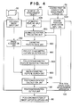
- Fig. 4 is a diagram illustrating the functional configuration of a measurement apparatus according to an embodiment of the present invention.
- Fig. 5 is a diagram illustrating the configuration of a measurement apparatus according to an embodiment of the present invention when used in a mixed reality application.
- Fig. 1 is a block diagram showing a measurement apparatus 100 and an image-capturing apparatus 50.
- Fig. 1 illustrates the flow of processing and data flow in the measurement apparatus 100.
- the configuration of the measurement apparatus 100 shown below is partially or entirely implemented as a result of execution of a control program stored in a ROM or RAM, not shown, by a CPU, not shown.
- the measurement apparatus 100 may be implemented by executing a control program executing the hereinafter described processing on a regular computer.
- an image-capturing apparatus 50 which captures images of a scene
- a coarse measurement apparatus 70 which acquires the general position and orientation of the image-capturing apparatus 50
- a captured-image-input unit 110 and a coarse input unit 130 (marked “coarse position/orientation input unit” in the figures).
- a 3D model 60 of a measurement object which describes geometric features used for measurement object alignment, is acquired from a geometric-feature input unit 120.
- the geometric-feature input unit 120 may be configured to accept as input (read) the 3D model 60 from loaded storage media or may be configured to accept the 3D model 60 as input from outside via a network etc.
- the purpose of the measurement apparatus 100 is to use captured image information to obtain the relative position and orientation of the image-capturing apparatus 50 with respect to the measurement object when the image-capturing apparatus 50 is capturing an image of a scene comprising the measurement object described by the 3D model 60 of the measurement object.
- the condition that permits position and orientation estimation by the measurement apparatus 100 is that an image of said measurement object is included in a captured image of a scene captured by the image-capturing apparatus 50. It should be noted that when there is no image of said measurement object in the captured image, the measurement values of the coarse measurement apparatus 70 may be used "as is”.
- the image-capturing apparatus 50 is a 2D image-capturing apparatus utilizing photoelectric conversion elements constituted by CCD or CMOS elements. Moreover, the image-capturing apparatus 50 sends a video signal to the measurement apparatus 100 via the captured-image-input unit 110.
- the captured-image-input unit 110 is configured to permit transmission of video signals via a signal cable (line) or wirelessly. Furthermore, it may take a form, in which the image-capturing apparatus 50 is incorporated into the measurement apparatus 100 or a form, in which an arrangement implementing processing by the measurement apparatus 100 is incorporated into the processor of the image-capturing apparatus 50.
- the 3D model 60 of the measurement object is a model including the 3D geometric information of the measurement object and comprises geometric features detected as edges in images captured by the image-capturing apparatus 50.
- CAD and other design data as the 3D model 60.
- configure it so as to permit input of values measured by measurement devices as a 3D model.
- commercially available 3D measurement applications may be used for editing the 3D model.
- the edges of wall surfaces and doors in the building can also be measured with measurement instruments.
- the target measurement object is provided on storage media that can be attached to and removed from the measurement apparatus 100 in order allow the measurement apparatus 100 to switch measurement objects. Accordingly, the geometric-feature input unit 120 of the measurement apparatus 100 is furnished with an interface capable of reading data from the removable storage media.
- 3D model information may be incorporated into the measurement apparatus 100 using nonvolatile memory or storage media.
- the 3D model 60 of the measurement object may be somehow provided to the measurement apparatus 100 prior to carrying out measurement. Accordingly, it may be specified by multiple 3D model data stored on external storage media as well as acquired from a remote server via a network.
- the measurement apparatus 100 may contain geometric-feature data detectable from captured images, the measurement apparatus 100 may be configured to comprise a processing unit used for converting various 3D-model data formats.
- the coarse measurement apparatus 70 is an apparatus used to provide the general position and orientation of the image-capturing apparatus 50.
- An apparatus can be used that measures 6DoF (six degrees of freedom), that is, position and orientation of a sensor in a space using magnetic fields or ultrasonic waves. It should be noted that it is also possible to utilize the coarse position and orientation of the image-capturing apparatus 50 obtained by disposing markers with graphical features located in known positions and detecting these markers from the captured images.
- the position and orientation measurement apparatus 100 is composed of an input unit used for inputting information from other devices, a processing unit used for estimating the relative position and orientation of the image-capturing apparatus with respect to the measurement object based on information from the input unit, and an output unit used for outputting the position and orientation of the image-capturing apparatus so that it can be used by other devices.
- the captured-image-input unit 110 which is a unit used for input, the geometric-feature input unit 120, and the coarse input unit 130 are explained below.
- the image-capturing apparatus 50 is connected to the measurement apparatus 100 by the captured-image-input unit 110.
- the captured-image-input unit 110 has a connector used for video signal input, which is connected to a video output terminal on the image-capturing apparatus 50 that conforms to video signal output specifications.
- the format of the 3D model 60 is a format that the measurement apparatus 100 supports.
- the geometric-feature input unit 120 is provided with the corresponding CAD format analysis capability, which makes it possible to handle any model data. It is assumed that, from respective model formats, it extracts and holds what corresponds to the image geometric features, whereby the measurement object used for estimating the position and orientation of the apparatus is detected in the captured image. In other words, the geometric-feature input unit 120 selects the model of the measurement object present in the captured image based on the position and orientation of the image-capturing apparatus 50 according to the coarse measurement apparatus 70, and holds it.
- the geometric features are comprised of one or more line segments and contain at least two points, that is, a 3D start point and end point, for each line segment. It should be noted that, as described below, both the start and the end point may be generated by clipping. If the coordinates of each point constituting a line segment are expressed in the model coordinate system established by the geometric features, they can be matched to real space by referring to the position and orientation in the model coordinate system and the scaling factor used during expansion to the actual spatial scale.
- the acquisition of the coarse position and orientation from the coarse measurement apparatus 70 will be explained next. It is assumed that the coarse measurement apparatus 70 measures the general position and orientation of the image-capturing apparatus based on information from sensors moving along with the image-capturing apparatus 50. In the present embodiment, it is assumed that the information of the coarse measurement apparatus 70 is acquired via serial communications.
- the coarse input unit 130 acquires the general position and orientation of the image-capturing apparatus 50, in which the sensors are installed, from the coarse measurement apparatus 70 via serial communications. Furthermore, offset adjustment may be performed on appropriate sensors in the coarse input unit 130 or coarse measurement apparatus 70.
- the image-acquisition unit 200 samples the captured image, that is, the video signal of the image-capturing apparatus 50, which is transmitted via the captured-image-input unit 110, and saves the captured image as 2D image data. It is assumed that processing performed by each unit of the measurement apparatus 100 is carried out in sync with the image capture timing of the image-capturing apparatus 50.
- a video synchronizing signal output from the image-capturing apparatus 50 may be used for confirmation of image capture timing.
- the distortion of the lens may be calibrated in advance and used to perform correction.
- the image-acquisition unit 200 holds parameters that approximate the distortion of the lens being used in the form of a mathematical model.
- another processing unit e.g. image-geometric-feature search unit 600
- the image-acquisition unit 200 uses the parameters being held to correct the distortion and supply the pixel density.
- the processing unit checking the pixel density can check the density at pixel locations corrected based on the lens distortion correction formula, which also makes it possible to maintain the linearity of edges in captured images in the range of distortion that permits approximation.
- a geometric-feature projection unit 300 in the measurement apparatus 100 in the present embodiment Processing performed by a geometric-feature projection unit 300 in the measurement apparatus 100 in the present embodiment is explained next.
- a "geometric feature" is assumed to be composed of two points: a start point and an end point.
- the coordinate system of the geometric features is assumed to have been converted to a reference coordinate system-based representation.
- h is obtained as a homogeneous coordinate transformation representation and [u x u y ] T is calculated using the obtained h.
- R 3x3 matrix
- t [t x t y t z ] is a parallel translation vector
- f x , f y are focal lengths in the horizontal and vertical direction and p x , p y are principal point coordinates in the horizontal and vertical direction.
- start points and end points of geometric features can be subjected to perspective projection transformation and transformed to points within a captured image in the camera coordinate system.
- captured images are obtained by sampling light that forms images on imaging elements such as a CCD or a CMOS through optical elements. For this reason, the range of imaging elements is predetermined.
- the geometric-feature projection unit 300 holds only geometric features whose start point or an end point is contained in the captured image region. When only one point, that is, either the start point or the end point, of a geometric feature is comprised within the captured image region, the point of intersection of said line segment with the boundary of the captured image region is used as a new start point or end point.
- Such processing is typical processing called "clipping" in computer graphics.
- projection geometric features sometimes exist in locations where they are obscured by other objects and cannot be observed.
- the projection geometric-feature selection unit 400 will be explained next.
- the projection-geometric-feature selection unit 400 subjects the respective geometric features projected by the geometric-feature projection unit 300 to processing that determines whether to use them for position and orientation calculation based on distances between geometric features onscreen (in the captured image).
- the projection-geometric-feature selection unit 400 obtains the distance to a projection geometric feature in the captured image.
- the distance D i to the projection geometric feature in the captured image is calculated in the following manner.
- distance to the start point and end point of the projection geometric features that have been selected for use among projection geometric features processed up to the (i-1)th one is obtained for the start point Ps(i) and end point Pe(i) of the i-th projection geometric feature that has been subjected to projection transformation.
- the shortest distance is then compared with a predetermined threshold value and it is determined that distances smaller than the threshold value will not be used.
- the line segments that are proximate line segments already selected for use, or those determined to have a length equal or less than D' are not used.
- the frequency of value checking in image regions where the hereinafter-described edge search in captured images is performed is reduced and efficient processing can be carried out.
- the use of the overlapping of the edge search regions of adjacent projection geometric features makes it possible to dynamically process observed edge changes due to changes in the positional relationship between the image-capturing apparatus and the measurement object.
- line segments that do not allow for sufficient information to be obtained for determining line segment direction are excluded from items subject to calculation.
- the projection-geometric-feature search setting unit 500 calculates points for carrying out edge search in the captured image for projection geometric features selected for use by the projection-geometric-feature selection unit 400 among the projection geometric features that have been subjected to perspective projection transformation by the geometric-feature projection unit 300.
- the setting of search start points and search corresponding points (search end points) for image geometric features by the projection-geometric-feature search setting unit 500 will be explained next with reference to Fig. 3 .
- equidistant search start points c (i,m) are set up along the line segment connecting Ps(i) and Pe(i).
- the range of m is from 0 to M i , with the M i obtained in accordance with the following formula using a predetermined search segment interval B.
- M i v i B
- a search for edges in the captured image is carried out in a direction normal to the measurement line segment from the search start points c (i,m) .
- a vector obtained by quantizing the normalized normal vector v ⁇ i in four directions that is, up, down, left, and right, or in eight directions, additionally including up-right, down-right, up-left, and down-left.
- Selecting normalized vector directions that have a small difference relative to the normalized normal vector v ⁇ i makes it possible to efficiently process image geometric feature searches.
- the image-geometric-feature search unit 600 detects image geometric features based on the pixel density between the search start points and search corresponding points set by the projection-geometric-feature search setting unit 500 in a captured image obtained from the image-acquisition unit 200. For instance, it detects points where the density of adjacent pixels that have been read is characterized by a significant density gradient of (points exceeding a predetermined threshold value) and holds the position of the pixels of interest at such time as the image geometric feature detection position.
- an efficient way to increase the overall efficiency of processing is to refer to the time elapsed since the moment when an image is acquired by the image-acquisition unit 200 and determine whether the elapsed time exceeds a predetermined value, with the detection processing set up to be interrupted if it exceeds it.
- the calculation unit 700 calculates and updates the relative position and orientation of the measurement object and image-capturing apparatus based on the distance between the positions of the image geometric features detected by the image-geometric-feature search unit 600 in the captured image and the positions of the projection measurement line segments of the measurement object corresponding thereto.
- position/orientation calculation unit calculates and updates the relative position and orientation of the measurement object and image-capturing apparatus based on the distance between the positions of the image geometric features detected by the image-geometric-feature search unit 600 in the captured image and the positions of the projection measurement line segments of the measurement object corresponding thereto.
- the updated position and orientation of the image-capturing apparatus can be obtained by carrying out optimization calculations so as to reduce the difference between the projected positions of the geometric features of the measurement object observed from the estimated position and orientation and the observed positions of the image geometric features in the actual captured image plane.
- measurement line segments are used as the geometric features.
- the distance between the observed positions of the image geometric features and the projected positions of the geometric features of the measurement object is regarded as an error and used as an error function E.
- E ⁇ t x ⁇ t y ⁇ t z ⁇ ⁇ x ⁇ ⁇ y ⁇ ⁇ z ⁇ x w ⁇ y w ⁇ z w u ⁇ - u is used as the error function.
- nonlinear optimization techniques can be applied in the present embodiment because it is sufficient to be able to reduce the distance in the observed image between the positions of the image geometric features and the projection geometric features obtained by projecting the geometric features of the measurement object onto the captured image. For instance, a method where, for a general estimated position and orientation, there is generated a large number of random combinations exhibiting slight differences in the vicinity of the variable values, errors are obtained for the respective combinations, and combinations with small error values are utilized.
- the position and orientation estimation based on the corresponding captured image is terminated, and the results (position and orientation of image-capturing apparatus 80) are output by the output unit 140. If the error is greater than the predetermined value, an updated position and orientation is passed on to the geometric-feature projection unit 300, and edge search result-based position and orientation estimation is carried out using the updated position and orientation. If the number of updates performed in the calculation unit 700 exceeds a predetermined value, it means that the estimation of the position and orientation did not go smoothly. In such a case, in the present embodiment, the values of the coarse input unit 130 are output to the output unit 140.
- the measurement apparatus 100 can output position and orientation calculation results, although they represent low-accuracy coarse position and orientation. At such time, a value indicating whether the position and orientation has been accurately determined can also be output to the output unit 140.
- the apparatus may be adapted to allow the user of the measurement apparatus 100 to determine whether the output position and orientation measurement values have been corrected to a high level of accuracy. For instance, in applications utilizing mixed reality technology it is assumed that position and orientation measurement is carried out continuously and information indicating that the position and orientation measurement process has not succeeded makes it possible to modify processing performed by an application.
- Embodiment 1 illustrated a case, in which line segments of a 3D model constituting a measurement object were used as geometric features, the use of line segments is not mandatory in actual practice. For instance, the present invention can be applied even if the geometric features are dots, circles, ovals, etc.
- the geometric features are dots
- their distribution in the projection image changes depending on the relative position of the image-capturing apparatus and measurement object. If the distance between dots already projected onto the projection image and the projected dots of said geometric features in the captured image is less than one pixel, then it will be difficult to separate and detect the respective image geometric features. For this reason, the problem can be solved by performing the same processing as in the above-described embodiment in the projection-geometric-feature selection unit 400 used in the present embodiment.
- Embodiment 1 described a method, in which a search is carried out in a captured image for image geometric features corresponding to the positions of projection geometric features and position and orientation is estimated so as to decrease the distances therebetween.
- the ordinary Sobel operator and Canny operator can be uses in the detection of line segments carried out during the detection of image geometric features in captured images.
- line segments detected by image processing in captured images referred to as edges as appropriate are called edge elements.
- edges possessing similar length, direction, etc. among edges located in the vicinity of the projection geometric features can be associated and position and orientation can be estimated so as to reduce the distances to these edge elements.
- redundant association processing can be reduced by making decisions regarding the use of geometric features in accordance with distances in the captured image.
- the geometric features required for position and orientation estimation are subject to considerable variation depending on the distance between the image-capturing apparatus 50 and the measurement object. For this reason, if processing cannot be performed in an efficient manner, it becomes difficult to carry out position and orientation estimation within the imaging interval of the camera.
- the geometric features required for the estimation of position and orientation may possess a certain length and may have various directions.
- processing that takes into consideration the sequence of processing of the geometric features required for position and orientation estimation makes it possible to process huge geometric features while maintaining the accuracy of position and orientation because the processing of the geometric features required for position and orientation estimation is completed even of the image geometric feature search process is interrupted.
- Fig. 4 is a flow chart illustrating the configuration of the measurement apparatus 100 of Embodiment 3, which has a geometric feature sort unit 800 representing geometric feature sorting means that determines the sequence of processing of the model. It should be noted that the configuration shown in Fig. 4 is same as the configuration of Embodiment 1 ( Fig. 1 ) except for the geometric feature sort unit 800. Therefore, explanations provided herein will focus on processing performed by the geometric feature sort unit 800.
- the geometric feature sort unit 800 computes the length of the projection geometric features in the captured image and sorts them from longest to shortest. Moreover, if dots and pixels distributed in the vicinity thereof are used as geometric features, sorting can be carried out using distribution values defining pixel distribution. It should be noted that, despite the fact that explanations herein refer to the length of the projection geometric features, in actual practice, to be able to achieve the effects of Embodiment 3, it is sufficient to perform sorting such that line segments permitting efficient image geometric feature detection during position and orientation estimation can be processed in a preferential manner.
- the geometric feature sort unit 800 carries out sorting by starting from features whose depth direction is close to the viewpoint, as a result of which edges what have significant influence on position and orientation accuracy can be processed first.
- Fig. 5 is a schematic diagram illustrating the way the measurement apparatus 100 according to Embodiment 5 is applied to compositing of virtual object CG with a measurement object based on mixed reality technology.
- the measurement object 10 is a 3D object of a known shape. It is assumed that the constituent surface, which has a curved surface, is comprised of multiple faces. Moreover, the angle at which the measurement object is viewed is not specified in a predetermined way.
- the image captured by the image-capturing apparatus 50 is inputted to the measurement apparatus 100 by the captured-image-input unit 110. Moreover, it is also connected to an image input unit 921 of a chroma-key compositing apparatus 920 in order to composite images. It is assumed that a 3D model 60 of the measurement object 10 has already been registered in the measurement apparatus 100.
- the measurement apparatus 100 When the measurement object 10 is present in the captured image, the measurement apparatus 100 outputs the results of position and orientation measurement of the image-capturing apparatus 50 using the output unit 140.
- the CG rendering apparatus 910 accepts the position and orientation of the image-capturing apparatus 50 from the measurement apparatus 100 via an input unit 911.
- the CG rendering apparatus 910 uses the position and orientation inputted from the input unit 911 as the CG viewpoint position and subjects virtual objects to CG rendering, outputting the rendered image to a CG image output unit 912.
- the CG rendering apparatus 910 renders two cylinders 941, which are virtual objects, on top of the measurement object 10 and outputs an image such as the virtual object CG image 940 using the CG image output unit 912.
- the background color of the virtual object CG image 940 is a chroma-key-matching color set by the chroma-key compositing apparatus 920.
- the chroma-key compositing apparatus 920 accepts the captured image of the image-capturing apparatus 50 from the image input unit 921 as input and gets the virtual object CG image 940 from a chroma-key target image input unit 922.
- the chroma-key compositing apparatus 920 then composites the virtual object CG image 940, in which regions having the chroma key-matching color are made transparent, with the captured image, and outputs the resultant composite image 930 using the chroma-key composite image output unit 923.
- the outputted composite image 930 turns into an image, in which there are two cylinders 941, that is, virtual objects, rendered on top of the captured measurement object.
- the position and orientation of the head unit can be matched with the real space being observed, which makes it possible to expect an improvement in operability based on mixed reality.
- the measurement apparatus 100, CG rendering apparatus 910, and chroma-key compositing apparatus 920 can be realized using a single computer program.
- the position and orientation of the image-capturing apparatus can be obtained in an efficient manner without being affected by the relative position relationship between the image-capturing apparatus and measurement object.
- the present invention can contemplate embodiments such as, for instance, systems, devices, methods, programs, or storage media, etc. Specifically, it may be applied to a system composed of a plurality of devices, as well as applied to an apparatus constituted by a single device.
- the present invention includes cases, wherein the functionality of the above-described embodiments is realized by supplying a software program to the system or apparatus directly or remotely and allowing the computer of the system or apparatus to read and execute the supplied program code.
- the supplied programs correspond to the flow charts depicted in the drawings of the embodiments.
- the program code installed on the computer may be an implementation of the present invention.
- embodiments may take various forms, such as object code, interpreter-executed programs, script data supplied to the OS, etc.
- the following media are suggested as computer-readable storage media used for supplying the program.
- it may be a floppy (TM) disk, a hard disk, an optical disk, a magneto-optical disk, an MO, a CD-ROM, a CD-R, a CD-RW, a magnetic tape, a nonvolatile memory card, ROM, or a DVD (DVD-ROM, DVD-R), etc.
- the downloaded program may be a compressed file with self-installation functionality.
- it can also be implemented by dividing the program code constituting the program of the present invention into a plurality of files and downloading the respective files from different homepages.
- WWW servers that allow a plurality of users to download program files used to implement the functional processing of the present invention on the computer are also included in the present invention.
- it may take the form of encrypting the program of the present invention, storing it on CD-ROMs or other storage media, and disseminating it among users.
- users who meet certain criteria may be allowed to download key information used to decrypt the encryption from a homepage through the Internet and use the key information to execute the encrypted program and install the program on a computer.
- the functionality of the embodiments may be implemented based on the instructions of the program in cooperation with an OS, etc. running on the computer.
- the OS, etc. carries out either part or all of the actual processing and the above-described functionality of the embodiments is implemented based on such processing.
- either part or all of the above-described functionality of the embodiments may be implemented by writing the program read from the recordable media to memory provided in an expansion unit connected to the computer or an expansion board inserted into the computer.
- the CPU, etc. provided in the expansion board or expansion unit carries out either part or all of the actual processing based on the instructions of the program.
- a further embodiment of the present invention provides a position/orientation measurement apparatus measuring the relative position and orientation of an image capturing apparatus capturing images of one or more measurement objects with respect to the measurement object
- the apparatus comprises: image acquiring means for acquiring a captured image from the image capturing apparatus; projection means for projecting geometric features present in a 3D model of the measurement object onto the captured image based on the position/orientation of the image capturing apparatus to obtain projection geometric features; selecting means for selecting projection geometric features to be used in calculation of the position/orientation from the projection geometric features obtained by the projection means based on distances between the projection geometric features in the captured image; and calculating means for calculating the relative position/orientation of the image capturing apparatus with respect to the measurement object using the projection geometric features selected by the selecting means and image geometric features corresponding to the selected projection geometric features detected in the captured image.
- a further embodiment of the present invention provides a control method for a position/orientation measurement apparatus measuring the relative position and orientation of an image capturing apparatus capturing images of one or more measurement objects with respect to the measurement object, wherein the method comprises the steps of: acquiring a captured image from the image capturing apparatus; projecting respective geometric features present in a 3D model of the measurement object onto the captured image based on the position/orientation of the image capturing apparatus to obtain projection geometric features; selecting projection geometric features to be used in calculation of the position/orientation from the projection geometric features obtained in the projecting step based on distances between the projection geometric features in the captured image; calculating the relative position/orientation of the image capturing apparatus with respect to the measurement object using the projection geometric features selected in the selection step and image geometric features corresponding to the selected projection geometric features detected in the captured image.
Applications Claiming Priority (1)
| Application Number | Priority Date | Filing Date | Title |
|---|---|---|---|
| JP2007117563A JP5538667B2 (ja) | 2007-04-26 | 2007-04-26 | 位置姿勢計測装置及びその制御方法 |
Publications (1)
| Publication Number | Publication Date |
|---|---|
| EP1986154A1 true EP1986154A1 (de) | 2008-10-29 |
Family
ID=39637657
Family Applications (1)
| Application Number | Title | Priority Date | Filing Date |
|---|---|---|---|
| EP08155173A Withdrawn EP1986154A1 (de) | 2007-04-26 | 2008-04-25 | Modellbasierte Schätzung der Kamerapose |
Country Status (4)
| Country | Link |
|---|---|
| US (2) | US8326021B2 (de) |
| EP (1) | EP1986154A1 (de) |
| JP (1) | JP5538667B2 (de) |
| CN (1) | CN101294793B (de) |
Cited By (6)
| Publication number | Priority date | Publication date | Assignee | Title |
|---|---|---|---|---|
| CN102222333A (zh) * | 2011-05-20 | 2011-10-19 | 同济大学 | 一种基于混合注册的地下工程移动增强现实方法及其装置 |
| WO2012048304A1 (en) * | 2010-10-07 | 2012-04-12 | Sungevity | Rapid 3d modeling |
| DE102010024054A1 (de) * | 2010-06-16 | 2012-05-10 | Fast Protect Ag | Verfahren zum Zuordnen eines Videobilds der realen Welt zu einem dreidimensionalen Computermodell der realen Welt |
| US9279602B2 (en) | 2007-10-04 | 2016-03-08 | Sungevity Inc. | System and method for provisioning energy systems |
| US9934334B2 (en) | 2013-08-29 | 2018-04-03 | Solar Spectrum Holdings Llc | Designing and installation quoting for solar energy systems |
| WO2020058641A1 (fr) | 2018-09-21 | 2020-03-26 | Diotasoft | Dispositif, systeme et procede de localisation, par un module de traitement, d'un module d'acquisition par rapport a un equipement a controler |
Families Citing this family (46)
| Publication number | Priority date | Publication date | Assignee | Title |
|---|---|---|---|---|
| JP4666060B2 (ja) * | 2008-11-14 | 2011-04-06 | 富士ゼロックス株式会社 | 情報処理装置、情報処理システム及びプログラム |
| CN101609552B (zh) * | 2009-03-30 | 2012-12-19 | 浙江工商大学 | 有限复杂背景下视频目标的特征检测方法 |
| JP5290864B2 (ja) * | 2009-05-18 | 2013-09-18 | キヤノン株式会社 | 位置姿勢推定装置及び方法 |
| JP5560600B2 (ja) * | 2009-07-09 | 2014-07-30 | 株式会社島津製作所 | ヘッドモーショントラッカ装置 |
| JP5393318B2 (ja) * | 2009-07-28 | 2014-01-22 | キヤノン株式会社 | 位置姿勢計測方法及び装置 |
| US9046355B2 (en) | 2009-07-29 | 2015-06-02 | Canon Kabushiki Kaisha | Measuring apparatus, measuring method, and program |
| US8948524B2 (en) * | 2009-10-29 | 2015-02-03 | Hewlett-Packard Development Company, L.P. | Joint image compression method and apparatus |
| JP2011175477A (ja) * | 2010-02-24 | 2011-09-08 | Canon Inc | 3次元計測装置、処理方法及びプログラム |
| JP5618569B2 (ja) * | 2010-02-25 | 2014-11-05 | キヤノン株式会社 | 位置姿勢推定装置及びその方法 |
| JP5771981B2 (ja) * | 2010-03-15 | 2015-09-02 | 株式会社リコー | 描画画像共有装置、データ処理方法、プログラムおよび記録媒体 |
| JP5612916B2 (ja) * | 2010-06-18 | 2014-10-22 | キヤノン株式会社 | 位置姿勢計測装置、その処理方法、プログラム、ロボットシステム |
| JP5496008B2 (ja) * | 2010-08-06 | 2014-05-21 | キヤノン株式会社 | 位置姿勢計測装置、位置姿勢計測方法、およびプログラム |
| CN102447942A (zh) * | 2010-10-09 | 2012-05-09 | 索尼公司 | 成像装置参数估计方法及应用它的方法、装置和系统 |
| JP5839929B2 (ja) * | 2010-11-19 | 2016-01-06 | キヤノン株式会社 | 情報処理装置、情報処理システム、情報処理方法及びプログラム |
| CN102609550B (zh) * | 2011-01-19 | 2015-11-25 | 鸿富锦精密工业(深圳)有限公司 | 产品三维模型自动摆正系统及方法 |
| JP5781351B2 (ja) * | 2011-03-30 | 2015-09-24 | 日本アビオニクス株式会社 | 撮像装置、その画素出力レベル補正方法、赤外線カメラシステム及び交換可能なレンズシステム |
| WO2012142250A1 (en) * | 2011-04-12 | 2012-10-18 | Radiation Monitoring Devices, Inc. | Augumented reality system |
| JP5778469B2 (ja) | 2011-04-28 | 2015-09-16 | 日本アビオニクス株式会社 | 撮像装置、画像生成方法、赤外線カメラシステム及び交換可能なレンズシステム |
| US8872852B2 (en) | 2011-06-30 | 2014-10-28 | International Business Machines Corporation | Positional context determination with multi marker confidence ranking |
| US9595115B1 (en) * | 2011-09-19 | 2017-03-14 | Amazon Technologies, Inc. | Visualizing change in augmented reality environments |
| JP5728399B2 (ja) * | 2012-01-19 | 2015-06-03 | 株式会社東芝 | 計測装置、方法及びプログラム |
| CN103377300A (zh) * | 2012-04-27 | 2013-10-30 | 鸿富锦精密工业(深圳)有限公司 | 探针校准路径模拟系统及方法 |
| US20130342568A1 (en) * | 2012-06-20 | 2013-12-26 | Tony Ambrus | Low light scene augmentation |
| US9025823B2 (en) * | 2013-03-12 | 2015-05-05 | Qualcomm Incorporated | Tracking texture rich objects using rank order filtering |
| US10412368B2 (en) | 2013-03-15 | 2019-09-10 | Uber Technologies, Inc. | Methods, systems, and apparatus for multi-sensory stereo vision for robotics |
| JP2014185996A (ja) * | 2013-03-25 | 2014-10-02 | Toshiba Corp | 計測装置 |
| US10262462B2 (en) | 2014-04-18 | 2019-04-16 | Magic Leap, Inc. | Systems and methods for augmented and virtual reality |
| US20150042789A1 (en) * | 2013-08-07 | 2015-02-12 | Blackberry Limited | Determining the distance of an object to an electronic device |
| JP6271953B2 (ja) * | 2013-11-05 | 2018-01-31 | キヤノン株式会社 | 画像処理装置、画像処理方法 |
| US9747680B2 (en) | 2013-11-27 | 2017-08-29 | Industrial Technology Research Institute | Inspection apparatus, method, and computer program product for machine vision inspection |
| US8976191B1 (en) | 2014-03-13 | 2015-03-10 | Qualcomm Incorporated | Creating a realistic color for a virtual object in an augmented reality environment |
| JP6525271B2 (ja) * | 2016-03-28 | 2019-06-05 | 国立研究開発法人農業・食品産業技術総合研究機構 | 残餌量測定装置および残餌量測定用プログラム |
| US9996936B2 (en) * | 2016-05-20 | 2018-06-12 | Qualcomm Incorporated | Predictor-corrector based pose detection |
| CN109891427A (zh) * | 2016-05-24 | 2019-06-14 | 艾迪密身份与安全美国有限责任公司 | 形状检测 |
| US10852913B2 (en) * | 2016-06-21 | 2020-12-01 | Samsung Electronics Co., Ltd. | Remote hover touch system and method |
| US10967862B2 (en) | 2017-11-07 | 2021-04-06 | Uatc, Llc | Road anomaly detection for autonomous vehicle |
| EP3528210A1 (de) * | 2018-02-14 | 2019-08-21 | Koninklijke Philips N.V. | Bildgebendes system und -verfahren mit stitching mehrerer bilder |
| JP7059701B2 (ja) * | 2018-03-08 | 2022-04-26 | 富士通株式会社 | 推定装置、推定方法、及び推定プログラム |
| CN108537845B (zh) * | 2018-04-27 | 2023-01-03 | 腾讯科技(深圳)有限公司 | 位姿确定方法、装置及存储介质 |
| US11120632B2 (en) * | 2018-10-16 | 2021-09-14 | Sony Interactive Entertainment Inc. | Image generating apparatus, image generating system, image generating method, and program |
| GB201818357D0 (en) * | 2018-11-12 | 2018-12-26 | Forsberg Services Ltd | Locating system |
| TWI700000B (zh) * | 2019-01-29 | 2020-07-21 | 威盛電子股份有限公司 | 全景影片影像穩定方法及裝置與影像穩定演算法評估方法 |
| CN112568935A (zh) * | 2019-09-29 | 2021-03-30 | 中慧医学成像有限公司 | 基于三维追踪相机的三维超声成像方法和系统 |
| US11315346B2 (en) * | 2020-01-16 | 2022-04-26 | Square Enix Co., Ltd. | Method for producing augmented reality image |
| CN115031635A (zh) * | 2020-08-31 | 2022-09-09 | 深圳市慧鲤科技有限公司 | 测量方法及装置、电子设备及存储介质 |
| KR20230087750A (ko) * | 2021-12-10 | 2023-06-19 | 삼성전자주식회사 | 3차원 모델링 장치 및 방법 |
Citations (1)
| Publication number | Priority date | Publication date | Assignee | Title |
|---|---|---|---|---|
| US20010043738A1 (en) | 2000-03-07 | 2001-11-22 | Sawhney Harpreet Singh | Method of pose estimation and model refinement for video representation of a three dimensional scene |
Family Cites Families (34)
| Publication number | Priority date | Publication date | Assignee | Title |
|---|---|---|---|---|
| JP2798393B2 (ja) * | 1988-08-12 | 1998-09-17 | 日本電信電話株式会社 | 物体の姿勢推定方法及びその装置 |
| FR2645300B1 (fr) * | 1989-03-29 | 1994-09-09 | Gen Electric Cgr | Procede de recalage automatique d'images |
| CA2035034C (en) * | 1989-06-20 | 1998-01-20 | Toshihiko Morita | Method for measuring position and orientation of object |
| JP2679490B2 (ja) * | 1991-11-08 | 1997-11-19 | 株式会社デンソー | 山積み部品の高速ピッキング装置 |
| US5819016A (en) * | 1993-10-05 | 1998-10-06 | Kabushiki Kaisha Toshiba | Apparatus for modeling three dimensional information |
| JP3101674B2 (ja) * | 1995-12-15 | 2000-10-23 | 岡山大学長 | Cad情報を用いた3次元認識手法及び装置 |
| JPH09178426A (ja) * | 1995-12-26 | 1997-07-11 | Tokyo Electric Power Co Inc:The | 認識対象物体の位置姿勢認識装置および位置姿勢認識方法 |
| JPH1089943A (ja) * | 1996-09-18 | 1998-04-10 | Nippon Telegr & Teleph Corp <Ntt> | 物体位置決め方法及び装置 |
| US5973699A (en) * | 1996-09-19 | 1999-10-26 | Platinum Technology Ip, Inc. | System and method for increasing the performance for real-time rendering of three-dimensional polygonal data |
| US7098435B2 (en) * | 1996-10-25 | 2006-08-29 | Frederick E. Mueller | Method and apparatus for scanning three-dimensional objects |
| JPH1196374A (ja) * | 1997-07-23 | 1999-04-09 | Sanyo Electric Co Ltd | 3次元モデリング装置、3次元モデリング方法および3次元モデリングプログラムを記録した媒体 |
| EP0918302B1 (de) * | 1997-11-24 | 2002-07-10 | Weiglhofer, Gerhard | Kohärenzdetektor |
| JP3862402B2 (ja) * | 1998-02-27 | 2006-12-27 | シャープ株式会社 | 3次元モデル生成装置および3次元モデル生成プログラムを記録したコンピュータ読取可能な記録媒体 |
| US6912293B1 (en) * | 1998-06-26 | 2005-06-28 | Carl P. Korobkin | Photogrammetry engine for model construction |
| JP3867410B2 (ja) * | 1998-09-02 | 2007-01-10 | 株式会社明電舎 | 三次元視覚位置決め方法及び装置 |
| JP2000088554A (ja) * | 1998-09-08 | 2000-03-31 | Nippon Telegr & Teleph Corp <Ntt> | 物体の特徴点探索方法及びその処理プログラムを記録した記録媒体ならびに特徴点探索装置 |
| JP4794708B2 (ja) * | 1999-02-04 | 2011-10-19 | オリンパス株式会社 | 3次元位置姿勢センシング装置 |
| JP2000275013A (ja) * | 1999-03-24 | 2000-10-06 | Mr System Kenkyusho:Kk | 視点位置姿勢の決定方法、コンピュータ装置および記憶媒体 |
| JP2001108410A (ja) * | 1999-10-07 | 2001-04-20 | Nikon Corp | 画像測定装置 |
| US7522186B2 (en) * | 2000-03-07 | 2009-04-21 | L-3 Communications Corporation | Method and apparatus for providing immersive surveillance |
| JP2001277167A (ja) * | 2000-03-31 | 2001-10-09 | Okayama Pref Gov Shin Gijutsu Shinko Zaidan | 3次元姿勢認識手法 |
| JP3433204B2 (ja) * | 2000-04-27 | 2003-08-04 | 株式会社東北テクノアーチ | 3次元モデル構成装置 |
| US7034820B2 (en) * | 2001-12-03 | 2006-04-25 | Canon Kabushiki Kaisha | Method, apparatus and program for processing a three-dimensional image |
| US6664121B2 (en) * | 2002-05-20 | 2003-12-16 | Nikon Precision, Inc. | Method and apparatus for position measurement of a pattern formed by a lithographic exposure tool |
| US6944265B2 (en) * | 2002-11-25 | 2005-09-13 | Ge Medical Systems Global Technology Company, Llc | Image pasting using geometry measurement and a flat-panel detector |
| JP4284644B2 (ja) * | 2003-05-23 | 2009-06-24 | 財団法人生産技術研究奨励会 | 3次元モデル構築システム及び3次元モデル構築プログラム |
| JP3738291B2 (ja) * | 2003-06-09 | 2006-01-25 | 住友大阪セメント株式会社 | 三次元形状測定装置 |
| CA2540084A1 (en) * | 2003-10-30 | 2005-05-12 | Nec Corporation | Estimation system, estimation method, and estimation program for estimating object state |
| JP4537104B2 (ja) * | 2004-03-31 | 2010-09-01 | キヤノン株式会社 | マーカ検出方法、マーカ検出装置、位置姿勢推定方法、及び複合現実空間提示方法 |
| JP4785416B2 (ja) * | 2005-05-11 | 2011-10-05 | キヤノン株式会社 | 位置姿勢計測方法及び装置 |
| JP4774818B2 (ja) * | 2005-06-07 | 2011-09-14 | トヨタ自動車株式会社 | 画像処理装置及び画像処理方法 |
| JP5063023B2 (ja) * | 2006-03-31 | 2012-10-31 | キヤノン株式会社 | 位置姿勢補正装置、位置姿勢補正方法 |
| JP4976756B2 (ja) * | 2006-06-23 | 2012-07-18 | キヤノン株式会社 | 情報処理方法および装置 |
| US7903166B2 (en) * | 2007-02-21 | 2011-03-08 | Sharp Laboratories Of America, Inc. | Methods and systems for display viewer motion compensation based on user image data |
-
2007
- 2007-04-26 JP JP2007117563A patent/JP5538667B2/ja active Active
-
2008
- 2008-04-23 US US12/108,078 patent/US8326021B2/en active Active
- 2008-04-25 EP EP08155173A patent/EP1986154A1/de not_active Withdrawn
- 2008-04-28 CN CN2008100934720A patent/CN101294793B/zh active Active
-
2012
- 2012-11-08 US US13/672,158 patent/US8639025B2/en active Active
Patent Citations (1)
| Publication number | Priority date | Publication date | Assignee | Title |
|---|---|---|---|---|
| US20010043738A1 (en) | 2000-03-07 | 2001-11-22 | Sawhney Harpreet Singh | Method of pose estimation and model refinement for video representation of a three dimensional scene |
Non-Patent Citations (6)
| Title |
|---|
| ALLEN P K ET AL.: "Localization methods for a mobile robot in urban environments", IEEE TRANSACTIONS ON ROBOTICS |
| ALLEN P K ET AL: "Localization Methods for a Mobile Robot in Urban Environments", IEEE TRANSACTIONS ON ROBOTICS, IEEE SERVICE CENTER, PISCATAWAY, NJ, US, vol. 20, no. 5, 1 October 2004 (2004-10-01), pages 851 - 864, XP011119599, ISSN: 1552-3098 * |
| KLEIN G ET AL: "Robust visual tracking for non-instrumented augmented reality", MIXED AND AUGMENTED REALITY, 2003. PROCEEDINGS. THE SECOND IEEE AND AC M INTERNATIONAL SYMPOSIUM ON 7-10 OCT. 2003, PISCATAWAY, NJ, USA,IEEE, 7 October 2003 (2003-10-07), pages 113 - 122, XP010662802, ISBN: 978-0-7695-2006-3 * |
| KLIEN G ET AL.: "Robust visual tracking for non-instrumented augmented reality", PROCEEDINGS OF THE SECOND IEEE AND ACM INTERNATIONAL SYMPOSIUM ON MIXED AND AUGMENTED REALITY |
| WUEST H ET AL.: "Adaptive line tracking with multiple hypotheses for augmented reality", PROCEEDINGS OF THE FOURTH IEEE AND ACM INTERNATIONAL SYMPOSIUM ON MIXED AND AUGMENTED REALITY |
| WUEST H ET AL: "Adaptive Line Tracking with Multiple Hypotheses for Augmented Reality", MIXED AND AUGMENTED REALITY, 2005. PROCEEDINGS. FOURTH IEEE AND ACM IN TERNATIONAL SYMPOSIUM ON VIENNA, AUSTRIA 05-08 OCT. 2005, PISCATAWAY, NJ, USA,IEEE, 5 October 2005 (2005-10-05), pages 62 - 69, XP010856761, ISBN: 978-0-7695-2459-7 * |
Cited By (10)
| Publication number | Priority date | Publication date | Assignee | Title |
|---|---|---|---|---|
| US9279602B2 (en) | 2007-10-04 | 2016-03-08 | Sungevity Inc. | System and method for provisioning energy systems |
| DE102010024054A1 (de) * | 2010-06-16 | 2012-05-10 | Fast Protect Ag | Verfahren zum Zuordnen eines Videobilds der realen Welt zu einem dreidimensionalen Computermodell der realen Welt |
| WO2012048304A1 (en) * | 2010-10-07 | 2012-04-12 | Sungevity | Rapid 3d modeling |
| AU2011312140B2 (en) * | 2010-10-07 | 2015-08-27 | Sungevity | Rapid 3D modeling |
| AU2011312140C1 (en) * | 2010-10-07 | 2016-02-18 | Sungevity | Rapid 3D modeling |
| CN102222333A (zh) * | 2011-05-20 | 2011-10-19 | 同济大学 | 一种基于混合注册的地下工程移动增强现实方法及其装置 |
| CN102222333B (zh) * | 2011-05-20 | 2013-01-02 | 同济大学 | 一种基于混合注册的地下工程移动增强现实方法及其装置 |
| US9934334B2 (en) | 2013-08-29 | 2018-04-03 | Solar Spectrum Holdings Llc | Designing and installation quoting for solar energy systems |
| WO2020058641A1 (fr) | 2018-09-21 | 2020-03-26 | Diotasoft | Dispositif, systeme et procede de localisation, par un module de traitement, d'un module d'acquisition par rapport a un equipement a controler |
| FR3086436A1 (fr) * | 2018-09-21 | 2020-03-27 | Diotasoft | Dispositif, systeme et procede de localisation, par un module de traitement, d’un module d’acquisition par rapport a un equipement a controler |
Also Published As
| Publication number | Publication date |
|---|---|
| US20080267454A1 (en) | 2008-10-30 |
| JP2008275391A (ja) | 2008-11-13 |
| US20130077854A1 (en) | 2013-03-28 |
| US8639025B2 (en) | 2014-01-28 |
| US8326021B2 (en) | 2012-12-04 |
| JP5538667B2 (ja) | 2014-07-02 |
| CN101294793A (zh) | 2008-10-29 |
| CN101294793B (zh) | 2011-09-07 |
Similar Documents
| Publication | Publication Date | Title |
|---|---|---|
| US8639025B2 (en) | Measurement apparatus and control method | |
| US10825198B2 (en) | 3 dimensional coordinates calculating apparatus, 3 dimensional coordinates calculating method, 3 dimensional distance measuring apparatus and 3 dimensional distance measuring method using images | |
| US7911503B2 (en) | Information processing apparatus and information processing method | |
| JP5580164B2 (ja) | 光学情報処理装置、光学情報処理方法、光学情報処理システム、光学情報処理プログラム | |
| US6381302B1 (en) | Computer assisted 2D adjustment of stereo X-ray images | |
| US8059889B2 (en) | Position and orientation measurement apparatus and control method thereof | |
| US10410089B2 (en) | Training assistance using synthetic images | |
| US20200005447A1 (en) | Computer aided rebar measurement and inspection system | |
| JP3859574B2 (ja) | 3次元視覚センサ | |
| US7092109B2 (en) | Position/orientation measurement method, and position/orientation measurement apparatus | |
| US9325969B2 (en) | Image capture environment calibration method and information processing apparatus | |
| JP5620200B2 (ja) | 点群位置データ処理装置、点群位置データ処理方法、点群位置データ処理システム、および点群位置データ処理プログラム | |
| JP5593177B2 (ja) | 点群位置データ処理装置、点群位置データ処理方法、点群位置データ処理システム、および点群位置データ処理プログラム | |
| WO2012020696A1 (ja) | 点群位置データ処理装置、点群位置データ処理システム、点群位置データ処理方法、および点群位置データ処理プログラム | |
| WO2012141235A1 (ja) | 三次元点群位置データ処理装置、三次元点群位置データ処理システム、三次元点群位置データ処理方法およびプログラム | |
| US20120162220A1 (en) | Three-dimensional model creation system | |
| JP6516558B2 (ja) | 位置情報処理方法 | |
| US7409152B2 (en) | Three-dimensional image processing apparatus, optical axis adjusting method, and optical axis adjustment supporting method | |
| US20120162387A1 (en) | Imaging parameter acquisition apparatus, imaging parameter acquisition method and storage medium | |
| JP2005077385A (ja) | 画像対応付け方法ならびに測量方法およびそれらを利用する計測システム | |
| JP2017151026A (ja) | 三次元情報取得装置、三次元情報取得方法、及びプログラム | |
| JP5409451B2 (ja) | 3次元変化検出装置 | |
| Liebold et al. | Integrated Georeferencing of LIDAR and Camera Data acquired from a moving platform | |
| Malysheva | Large-scale multimodal sensor fusion and object detection | |
| JP2004213278A (ja) | 画像処理装置、画像処理方法、画像処理プログラム、記録媒体及び電子機器 |
Legal Events
| Date | Code | Title | Description |
|---|---|---|---|
| PUAI | Public reference made under article 153(3) epc to a published international application that has entered the european phase |
Free format text: ORIGINAL CODE: 0009012 |
|
| AK | Designated contracting states |
Kind code of ref document: A1 Designated state(s): AT BE BG CH CY CZ DE DK EE ES FI FR GB GR HR HU IE IS IT LI LT LU LV MC MT NL NO PL PT RO SE SI SK TR |
|
| AX | Request for extension of the european patent |
Extension state: AL BA MK RS |
|
| 17P | Request for examination filed |
Effective date: 20090429 |
|
| 17Q | First examination report despatched |
Effective date: 20090602 |
|
| AKX | Designation fees paid |
Designated state(s): DE FR GB IT NL |
|
| STAA | Information on the status of an ep patent application or granted ep patent |
Free format text: STATUS: THE APPLICATION HAS BEEN WITHDRAWN |
|
| 18W | Application withdrawn |
Effective date: 20160129 |