EP1985889A1 - Schwingungsdämpfer mit amplitudenselektiver Dämpfkraft - Google Patents
Schwingungsdämpfer mit amplitudenselektiver Dämpfkraft Download PDFInfo
- Publication number
- EP1985889A1 EP1985889A1 EP08005266A EP08005266A EP1985889A1 EP 1985889 A1 EP1985889 A1 EP 1985889A1 EP 08005266 A EP08005266 A EP 08005266A EP 08005266 A EP08005266 A EP 08005266A EP 1985889 A1 EP1985889 A1 EP 1985889A1
- Authority
- EP
- European Patent Office
- Prior art keywords
- ring
- piston
- assembly
- section
- assembly according
- Prior art date
- Legal status (The legal status is an assumption and is not a legal conclusion. Google has not performed a legal analysis and makes no representation as to the accuracy of the status listed.)
- Granted
Links
- 238000013016 damping Methods 0.000 title claims description 8
- 230000001419 dependent effect Effects 0.000 title 1
- 238000010248 power generation Methods 0.000 abstract 1
- 238000005516 engineering process Methods 0.000 description 2
- 238000004519 manufacturing process Methods 0.000 description 2
- 238000005245 sintering Methods 0.000 description 2
- 125000006850 spacer group Chemical group 0.000 description 2
- 238000000418 atomic force spectrum Methods 0.000 description 1
Images


Classifications
-
- F—MECHANICAL ENGINEERING; LIGHTING; HEATING; WEAPONS; BLASTING
- F16—ENGINEERING ELEMENTS AND UNITS; GENERAL MEASURES FOR PRODUCING AND MAINTAINING EFFECTIVE FUNCTIONING OF MACHINES OR INSTALLATIONS; THERMAL INSULATION IN GENERAL
- F16F—SPRINGS; SHOCK-ABSORBERS; MEANS FOR DAMPING VIBRATION
- F16F9/00—Springs, vibration-dampers, shock-absorbers, or similarly-constructed movement-dampers using a fluid or the equivalent as damping medium
- F16F9/32—Details
- F16F9/50—Special means providing automatic damping adjustment, i.e. self-adjustment of damping by particular sliding movements of a valve element, other than flexions or displacement of valve discs; Special means providing self-adjustment of spring characteristics
- F16F9/512—Means responsive to load action, i.e. static load on the damper or dynamic fluid pressure changes in the damper, e.g. due to changes in velocity
- F16F9/5126—Piston, or piston-like valve elements
Definitions
- the invention relates to a vibration damper with amplitude-selective damping force according to the preamble of patent claim 1.
- the piston assembly comprises a conventional piston with valve discs and an additional unit for the function of the amplitude-selective Dämpfkrafterzeugung.
- the assembly has a sleeve-shaped base support with a stop surface for an axially movable switching ring.
- On the lateral surface of the base support a spacer sleeve is arranged with inside grooves, wherein the grooves and the lateral surface form bypass channels to a flow connection between the outer circumferential surface of the spacer sleeve and the inner wall of a cylinder.
- a clamping ring ensures a radial and axial fixation of the assembly on the piston. In the clamping ring connecting channels are executed on the described bypass channels. The manufacture of the items is quite difficult, so that considerable production costs incurred.
- the object of the present invention is to further develop an amplitude-selective assembly in which the problems known from the prior art are eliminated.
- the object is achieved in that the distributor section and the sleeve portion are made in one piece and form a tension chain with the piston via a common clamping ring.
- a head ring at the opposite end of the distributor portion of the sleeve portion of the stop surfaces for the switching ring.
- the head ring has a centering projection, which cooperates with an inner lateral surface of the sleeve portion.
- An abutment surface is formed by a disc arrangement.
- the disc assembly can take over a variety of combination multiple discs additional functions.
- the head ring has in the direction of the sleeve portion a step profile for supporting the Scheibencontaminatednung, which forms an annular groove for an axially movable valve ring with a step of the stepped profile. This measure also serves to optimize the sintering technology of the components
- the distributor section also has at least one shoulder oriented in the direction of the piston, which shoulder, together with an axial end face of the piston, forms an annular groove for a valve ring.
- the FIG. 1 shows a sectional view through a vibration damper 1.
- the vibration damper comprises an axially movable piston rod 3, on which a Piston 5 with valve disks 7; 9 are arranged.
- the piston is followed on a piston rod pin 11 by a structural unit 13 for producing an amplitude-selective damping force.
- the assembly 13 comprises a manifold portion 15 and a sleeve portion 17, which form a one-piece component.
- the distributor section 15 has, in the direction of the piston 5, a shoulder 19 which forms an annular groove 23 for a valve ring 25 with an end face 21 of the piston 5.
- This valve ring 25 controls the inflow and outflow of bypasses 27 within the sleeve portion 17, on its outer circumferential surface at least one axially extending groove as a flow connection 29 between a piston rod side and a piston rod remote working space 31; 33 in a cylinder 35 has.
- the flow connection 29 in turn is characterized by a between two stop surfaces 37; 39 axially movable switching ring 41 controlled.
- a first stop surface 37 is formed by the distributor section 15.
- At the opposite end of the sleeve portion 17 carries a head ring 43 a second stop surface 39.
- the second stop surface 39 is formed by a disc assembly 45.
- On the head ring 43 is in the direction of the sleeve portion 17, a stepped profile 47 for supporting the disc assembly 45 is executed, which forms an annular groove 49 for a second axially movable valve ring 51 together with a step of the stepped profile.
- the head ring 43 has a centering projection 53, which cooperates with an inner circumferential surface 55 of the sleeve portion 17, so that the piston 5 with the one-piece distributor portion sleeve portion 15; 17, the head ring 43 and a clamping ring 57 form a tension chain.
- the first valve ring 25 closes the direct flow of damping medium into the flow connection 29. Outlet openings 59 of the bypasses 27 are opened until the switching ring 41 comes to rest on the second stop surface 39.
- a smaller recess 70 in the abutment surface 39 determines the then effective bypass cross-section.
- the effective throttle area is formed by a recess within a pilot disk 61 between the second valve ring 51 and the head ring 47.
- a centering ring 63 clamps the pre-opening disk 61 between the head ring 47 and the disk assembly 45.
Landscapes
- Engineering & Computer Science (AREA)
- General Engineering & Computer Science (AREA)
- Physics & Mathematics (AREA)
- Fluid Mechanics (AREA)
- Mechanical Engineering (AREA)
- Fluid-Damping Devices (AREA)
- Buildings Adapted To Withstand Abnormal External Influences (AREA)
- Control Of Turbines (AREA)
Abstract
Description
- Die Erfindung betrifft einen Schwingungsdämpfer mit amplitudenselektiver Dämpfkraft gemäß dem Oberbegriff von Patentanspruch 1.
- Aus der
DE 10 2005 020 293 A1 ,Fig. 3 , ist ein gattungsbildender Schwingungsdämpfer bekannt, dessen Kolbenanordnung einen konventionellen Kolben mit Ventilscheiben und eine zusätzliche Baueinheit für die Funktion der amplitudenselektiven Dämpfkrafterzeugung aufweist. Die Baueinheit verfügt über einen hülsenförmigen Grundträger mit einer Anschlagfläche für einen axial beweglichen Schaltring. Auf der Mantelfläche des Grundträgers ist eine Distanzhülse mit innenseitigen Nuten angeordnet, wobei die Nuten und die Mantelfläche Bypasskanäle zu einer Strömungsverbindung zwischen der äußeren Mantelfläche der Distanzhülse und der Innenwandung eines Zylinders bilden. Ein Klemmring sorgt für eine radiale und axiale Fixierung der Baueinheit am Kolben. In dem Klemmring sind Anschlusskanäle an die beschriebenen Bypasskanäle ausgeführt. Die Herstellung der Einzelteile gestaltet sich ziemlich schwierig, so dass beträchtliche Fertigungskosten anfallen. - Dieses Konstruktionsprinzip erfordert eine Kolbenmutter für die Fixierung des Kolbens und der Ventilscheiben auf einem Kolbenstangenzapfen. Eine zweite Schraubmutter sichert die Baueinheit am Kolben. Schon bei einem konventionellen Kolbenventil wird viel Sorgfalt auf die Sicherung der Kolbenmutter verwendet, da eine gelöste Kolbenmutter u. U. den völligen Ausfall der Dämpffunktion mit sich bringen könnte.
- Die Aufgabe der vorliegenden Erfindung besteht darin, eine amplitudenselektive Baueinheit derart weiterzuentwickeln, bei denen die aus dem Stand der Technik bekannten Probleme behoben sind.
- Erfindungsgemäß wird die Aufgabe dadurch gelöst, dass der Verteilerabschnitt und der Hülsenabschnitt einteilig ausgeführt sind und mit dem Kolben über einen gemeinsamen Spannring eine Verspannungskette bilden.
- Der sehr einfache Aufbau der einzelnen Bauteile der Verspannungskette vereinfacht die sintertechnische Herstellung. Des Weiteren wird im Vergleich zum genannten Stand der Technik ein Befestigungsmittel eingespart, für das kein Sicherungswand zu betreiben ist.
- In weiterer vorteilhafter Ausgestaltung der Erfindung trägt ein Kopfring an dem dem Verteilerabschnitt gegenüberliegenden Ende des Hülsenabschnitts eine der Anschlagflächen für den Schaltring. Dadurch kann das Bauteil Verteilerabschnitt-Hülsenabschnitt ohne Hinterschneidungen ausgeführt werden.
- Gemäß einem vorteilhaften Unteranspruch weist der Kopfring einen Zentrieransatz auf, der mit einer Innenmantelfläche des Hülsenabschnitts zusammenwirkt.
- Eine Anschlagfläche wird von einer Scheibenanordnung gebildet. Die Scheibenanordnung kann durch eine vielfältige Kombination mehrere Scheiben zusätzliche Funktionen übernehmen.
- Der Kopfring weist in Richtung des Hülsenabschnitts ein Stufenprofil zur Abstützung der Scheibenabordnung auf, die mit einer Stufe des Stufenprofils eine Ringnut für einen axial beweglichen Ventilring bildet. Auch diese Maßnahme dient der Optimierung der sintertechnischen Herstellung der Bauteile
- Deshalb weist auch der Verteilerabschnitt mindestens einen in Richtung des Kolbens ausgerichteten Absatz auf, der zusammen mit einer axialen Stirnfläche des Kolbens eine Ringnut für einen Ventilring bildet.
- Anhand der folgenden Figurenbeschreibung soll die Erfindung näher erläutert werden. Es zeigt:
- Fig. 1
- Schnitt durch einen Schwingungsdämpfer im Bereich eines Kolbens
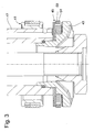
- Fig. 2 u. 3
- Detaildarstellung im Bereich einer Anschlagfläche für einen axial beweglichen Schaltring
- Die
Figur 1 zeigt eine Schnittdarstellung durch einen Schwingungsdämpfer 1. Der Schwingungsdämpfer umfasst eine axiale bewegliche Kolbenstange 3, an der ein Kolben 5 mit Ventilscheiben 7; 9 angeordnet sind. Dem Kolben schließt sich auf einem Kolbenstangenzapfen 11 eine Baueinheit 13 zur Erzeugung einer amplitudenselektiven Dämpfkraft an. Die Baueinheit 13 umfasst einen Verteilerabschnitt 15 und einen Hülsenabschnitt 17, die ein einteiliges Bauteil bilden. Der Verteilerabschnitt 15 weist in Richtung des Kolbens 5 einen Absatz 19 auf, der mit einer Stirnfläche 21 des Kolbens 5 eine Ringnut 23 für einen Ventilring 25 bildet. Dieser Ventilring 25 steuert den Zu- und Abfluss von Bypässen 27 innerhalb des Hülsenabschnitts 17, der auf seiner äußeren Mantelfläche mindestens eine axial verlaufende Nut als Strömungsverbindung 29 zwischen einem kolbenstangenseitigen und einem kolbenstangenfernen Arbeitsraum 31; 33 in einem Zylinder 35 aufweist. - Die Strömungsverbindung 29 wiederum wird von einem zwischen zwei Anschlagflächen 37; 39 axial beweglichen Schaltring 41 gesteuert. Eine erste Anschlagfläche 37 wird von dem Verteilerabschnitt 15 gebildet. Am gegenüberliegenden Ende des Hülsenabschnitts 17 trägt ein Kopfring 43 eine zweite Anschlagfläche 39. Die zweite Anschlagfläche 39 wird von einer Scheibenanordnung 45 gebildet. Am Kopfring 43 ist in Richtung des Hülsenabschnitts 17 ein Stufenprofil 47 zur Abstützung der Scheibenanordnung 45 ausgeführt, die zusammen mit einer Stufe des Stufenprofils eine Ringnut 49 für einen zweiten axial beweglichen Ventilring 51 bildet.
- Der Kopfring 43 verfügt über einen Zentrieransatz 53, der mit einer Innenmantelfläche 55 des Hülsenabschnitts 17 zusammenwirkt, so dass der Kolben 5 mit dem einteiligen Verteilerabschnitt-Hülsenabschnitt 15; 17, dem Kopfring 43 und einem Spannring 57 eine Verspannungskette bilden.
- Bei einer Ausfahrbewegung der Kolbenstange 3 in Richtung des kolbenstangenseitigen Arbeitsraums 31 verschließt der erste Ventilring 25 den direkten Zustrom von Dämpfmedium in die Strömungsverbindung 29. Austrittsöffnungen 59 der Bypässe 27 sind solange geöffnet, bis der Schaltring 41 auf der zweiten Anschlagfläche 39 zur Anlage kommt. Während der weiteren Ausfahrbewegung bestimmt eine im Vergleich zur Aussparung in der Voröffnungsscheibe 61 kleinere Aussparung 70 in der Anschlagfläche 39 den dann wirksamen Bypassquerschnitt. Innerhalb einer Betriebsbewegung des Schaltrings 41 zwischen den beiden Anschlagflächen 37; 39 wird der wirksame Drosselquerschnitt von einer Aussparung innerhalb einer Voröffnungsscheibe 61 zwischen dem zweiten Ventilring 51 und dem Kopfring 47 gebildet. Ein Zentrierring 63 verspannt die Voröffnungsscheibe 61 zwischen dem Kopfring 47 und der Scheibenanordnung 45.
- Während einer Kolbenstangeneinfahrbewegung legt sich der erste Ventilring 25 an die Stirnfläche 21 des Kolbens 5 an. Mindestens eine Rille 65 verhindert den vollständigen Verschluss der Bypassöffnungen. Zusätzlich kann das Dämpfmedium zwischen dem ersten Ventilring 25 und einem Absatz 67 des Verteilerabschnitts 15 aus der Strömungsverbindung 29 abfließen, bis der Schaltring 41 an der ersten Anschlagfläche 37 zur Anlage kommt. Synchron zur Kolbenstangeneinfahrbewegung legt sich der zweite Ventilring 51 an die Scheibenanordnung 45 (
Fig. 3 ) an, so dass ein im Vergleich zum Voröffnungsquerschnitt 61 zumindest gleichgroßer Voröffnungsquerschnitt 69 zur Verfügung steht. Die Position des von der Scheibenanordnung 45 abgehobenen Schaltrings 41 hat bei einer Kolbenstangeneinfahrbewegung keinen Einfluss auf die Dämpfkrafteinstellung, die von dem Voröffnungsquerschnitt 69 in der Scheibenanordnung 45 bestimmt wird. - Wenn der Schaltring 41 eine der Anschlagflächen 37; 39 erreicht hat, öffnen richtungsabhängig die Ventilscheiben 5; 7 und bestimmen den weiteren Dämpfkraftverlauf.
Claims (6)
- Baueinheit in einem Schwingungsdämpfer zur Erzeugung einer amplitudenselektiven Dämpfkraft, umfassend einen an einem Kolben fixierten Verteilerabschnitt, der über einen Anschluss eine Dämpfmittelströmung zwischen einer Strömungsverbindung und mindestens einem Bypass innerhalb eines Hülsenabschnitts der Baueinheit steuert, wobei die Baueinheit einen zwischen zwei Anschlagflächen axial beweglichen Schaltring aufweist, der die Strömungsverbindung steuert, und ein Befestigungsmittel die Baueinheit auf einer Kolbenstange des Schwingungsdämpfers fixiert,
dadurch gekennzeichnet,
dass der Verteilerabschnitt (15) und der Hülsenabschnitt (17) einteilig ausgeführt sind und mit dem Kolben (5) über einen gemeinsamen Spannring (57) eine Verspannungskette bilden. - Baueinheit nach Anspruch 1,
dadurch gekennzeichnet,
dass ein Kopfring (43) an dem dem Verteilerabschnitt (15) gegenüberliegenden Ende des Hülsenabschnitts (17) eine der Anschlagflächen (37; 39) für den Schaltring (41) trägt. - Baueinheit nach Anspruch 2,
dadurch gekennzeichnet,
dass der Kopfring (43) einen Zentrieransatz (53) aufweist, der mit einer Innenmantelfläche (55) des Hülsenabschnitts (17) zusammenwirkt. - Baueinheit nach Anspruch 2,
dadurch gekennzeichnet,
dass die Anschlagfläche (39) von einer Scheibenanordnung (45) gebildet wird. - Baueinheit nach Anspruch 2,
dadurch gekennzeichnet,
dass der Kopfring (43) in Richtung des Hülsenabschnitts (17) ein Stufenprofil (47) zur Abstützung der Scheibenabordnung (45) aufweist, die mit einer Stufe des Stufenprofils eine Ringnut (49) für einen axial beweglichen Ventilring (51) bildet. - Baueinheit nach Anspruch 1,
dadurch gekennzeichnet,
dass der Verteilerabschnitt (15) mindestens einen in Richtung des Kolbens 5 ausgerichteten Absatz (19) aufweist, der zusammen mit einer axialen Stirnfläche (21) des Kolbens (5) eine Ringnut (23) für einen Ventilring (25) bildet.
Applications Claiming Priority (1)
| Application Number | Priority Date | Filing Date | Title |
|---|---|---|---|
| DE102007019897A DE102007019897B3 (de) | 2007-04-27 | 2007-04-27 | Schwingungsdämpfer mit amplitudenselektiver Dämpfkraft |
Publications (2)
| Publication Number | Publication Date |
|---|---|
| EP1985889A1 true EP1985889A1 (de) | 2008-10-29 |
| EP1985889B1 EP1985889B1 (de) | 2010-05-05 |
Family
ID=39661372
Family Applications (1)
| Application Number | Title | Priority Date | Filing Date |
|---|---|---|---|
| EP08005266A Not-in-force EP1985889B1 (de) | 2007-04-27 | 2008-03-20 | Schwingungsdämpfer mit amplitudenselektiver Dämpfkraft |
Country Status (3)
| Country | Link |
|---|---|
| EP (1) | EP1985889B1 (de) |
| AT (1) | ATE467065T1 (de) |
| DE (2) | DE102007019897B3 (de) |
Cited By (1)
| Publication number | Priority date | Publication date | Assignee | Title |
|---|---|---|---|---|
| CN113775686A (zh) * | 2021-11-10 | 2021-12-10 | 常州龙翔气弹簧股份有限公司 | 一种平衡式气弹簧 |
Citations (2)
| Publication number | Priority date | Publication date | Assignee | Title |
|---|---|---|---|---|
| US20050056501A1 (en) * | 2003-09-15 | 2005-03-17 | De Molina Simon Anne | Stroke dependent damping |
| DE102005020293A1 (de) | 2005-04-30 | 2006-11-09 | Zf Friedrichshafen Ag | Schwingungsdämpfer mit amplitudenselektiver Dämpfkraft |
Family Cites Families (2)
| Publication number | Priority date | Publication date | Assignee | Title |
|---|---|---|---|---|
| US6352145B1 (en) * | 1998-10-07 | 2002-03-05 | Tenneco Automotive Inc. | Stroke dependent damping |
| DE102004058965B4 (de) * | 2004-12-08 | 2010-07-08 | Zf Friedrichshafen Ag | Schwingungsdämpfer mit amplitudenselektiver Dämpfkraft |
-
2007
- 2007-04-27 DE DE102007019897A patent/DE102007019897B3/de not_active Expired - Fee Related
-
2008
- 2008-03-20 AT AT08005266T patent/ATE467065T1/de active
- 2008-03-20 EP EP08005266A patent/EP1985889B1/de not_active Not-in-force
- 2008-03-20 DE DE502008000606T patent/DE502008000606D1/de active Active
Patent Citations (2)
| Publication number | Priority date | Publication date | Assignee | Title |
|---|---|---|---|---|
| US20050056501A1 (en) * | 2003-09-15 | 2005-03-17 | De Molina Simon Anne | Stroke dependent damping |
| DE102005020293A1 (de) | 2005-04-30 | 2006-11-09 | Zf Friedrichshafen Ag | Schwingungsdämpfer mit amplitudenselektiver Dämpfkraft |
Cited By (2)
| Publication number | Priority date | Publication date | Assignee | Title |
|---|---|---|---|---|
| CN113775686A (zh) * | 2021-11-10 | 2021-12-10 | 常州龙翔气弹簧股份有限公司 | 一种平衡式气弹簧 |
| CN113775686B (zh) * | 2021-11-10 | 2022-02-11 | 常州龙翔气弹簧股份有限公司 | 一种平衡式气弹簧 |
Also Published As
| Publication number | Publication date |
|---|---|
| EP1985889B1 (de) | 2010-05-05 |
| DE502008000606D1 (de) | 2010-06-17 |
| ATE467065T1 (de) | 2010-05-15 |
| DE102007019897B3 (de) | 2008-10-16 |
Similar Documents
| Publication | Publication Date | Title |
|---|---|---|
| EP3212958B1 (de) | Verfahren zum betreiben eines regelbaren schwingungsdämpfers für kraftfahrzeuge | |
| WO2016131908A1 (de) | Regelbarer schwingungsdämpfer | |
| DE102007001363A1 (de) | Injektor zum Einspritzen von Kraftstoff in Brennräume von Brennkraftmaschinen | |
| DE102014215199A1 (de) | Verstellbare Dämpfventileinrichtung | |
| EP1552135A1 (de) | Kraftstoffeinspritzvorrichtung für eine brennkraftmaschine | |
| DE102015218292A1 (de) | Verstellbare Dämpfventileinrichtung für einen Schwingungsdämpfer | |
| DE102005059169A1 (de) | Kraftstoffinjektor mit direkt betätigbarem Einspritzventilglied | |
| DE10057495B4 (de) | Injektorgehäuse mit einer Aktoreinheit | |
| DE4225350A1 (de) | Kraftstoffeinspritzpumpe für Brennkraftmaschinen | |
| DE102008005534A1 (de) | Kraftstoffinjektor | |
| EP1985889B1 (de) | Schwingungsdämpfer mit amplitudenselektiver Dämpfkraft | |
| DE102016225767A1 (de) | Dämpfventil | |
| EP1433951A1 (de) | Kraftstoffeinspritzventil für Brennkraftmaschinen | |
| EP3649367B1 (de) | Dämpfventil für einen schwingungsdämpfer | |
| DE102007029969A1 (de) | Schnellschaltender Kraftstoffinjektor für hohe Einspritzdrücke | |
| DE102016208055A1 (de) | Kraftstoffeinspritzventil für Brennkraftmaschinen | |
| DE102006062216A1 (de) | Kraftstoffinjektor | |
| EP1658427A1 (de) | Kraftstoffeinspritzventil für brennkraftmaschinen | |
| DE2726296A1 (de) | Kraftstoffeinspritzduese | |
| EP2824310B1 (de) | Kraftstoffeinspritzventil für Brennkraftmaschinen | |
| DE102007019904B3 (de) | Schwingungsdämpfer mit amplitudenselektiver Dämpfkraft | |
| EP1559908A1 (de) | Integrierter hydraulischer Druckübersetzer für Kraftstoffinjektoren an Hochdruckspeichereinspritzsystemen. | |
| DE102009000282A1 (de) | Kraftstoff-Injektor | |
| DE102004044462A1 (de) | Steuerventil für einen Injektor | |
| DE102006012842A1 (de) | Kraftstoffeinspritzventile für Brennkraftmaschinen |
Legal Events
| Date | Code | Title | Description |
|---|---|---|---|
| PUAI | Public reference made under article 153(3) epc to a published international application that has entered the european phase |
Free format text: ORIGINAL CODE: 0009012 |
|
| 17P | Request for examination filed |
Effective date: 20080905 |
|
| AK | Designated contracting states |
Kind code of ref document: A1 Designated state(s): AT BE BG CH CY CZ DE DK EE ES FI FR GB GR HR HU IE IS IT LI LT LU LV MC MT NL NO PL PT RO SE SI SK TR |
|
| AX | Request for extension of the european patent |
Extension state: AL BA MK RS |
|
| AKX | Designation fees paid |
Designated state(s): AT BE BG CH CY CZ DE DK EE ES FI FR GB GR HR HU IE IS IT LI LT LU LV MC MT NL NO PL PT RO SE SI SK TR |
|
| GRAP | Despatch of communication of intention to grant a patent |
Free format text: ORIGINAL CODE: EPIDOSNIGR1 |
|
| GRAS | Grant fee paid |
Free format text: ORIGINAL CODE: EPIDOSNIGR3 |
|
| GRAA | (expected) grant |
Free format text: ORIGINAL CODE: 0009210 |
|
| AK | Designated contracting states |
Kind code of ref document: B1 Designated state(s): AT BE BG CH CY CZ DE DK EE ES FI FR GB GR HR HU IE IS IT LI LT LU LV MC MT NL NO PL PT RO SE SI SK TR |
|
| REG | Reference to a national code |
Ref country code: GB Ref legal event code: FG4D Free format text: NOT ENGLISH |
|
| REG | Reference to a national code |
Ref country code: CH Ref legal event code: EP |
|
| REG | Reference to a national code |
Ref country code: IE Ref legal event code: FG4D Free format text: LANGUAGE OF EP DOCUMENT: GERMAN |
|
| REF | Corresponds to: |
Ref document number: 502008000606 Country of ref document: DE Date of ref document: 20100617 Kind code of ref document: P |
|
| REG | Reference to a national code |
Ref country code: NL Ref legal event code: VDEP Effective date: 20100505 |
|
| LTIE | Lt: invalidation of european patent or patent extension |
Effective date: 20100505 |
|
| PG25 | Lapsed in a contracting state [announced via postgrant information from national office to epo] |
Ref country code: ES Free format text: LAPSE BECAUSE OF FAILURE TO SUBMIT A TRANSLATION OF THE DESCRIPTION OR TO PAY THE FEE WITHIN THE PRESCRIBED TIME-LIMIT Effective date: 20100816 Ref country code: SE Free format text: LAPSE BECAUSE OF FAILURE TO SUBMIT A TRANSLATION OF THE DESCRIPTION OR TO PAY THE FEE WITHIN THE PRESCRIBED TIME-LIMIT Effective date: 20100505 Ref country code: NO Free format text: LAPSE BECAUSE OF FAILURE TO SUBMIT A TRANSLATION OF THE DESCRIPTION OR TO PAY THE FEE WITHIN THE PRESCRIBED TIME-LIMIT Effective date: 20100805 Ref country code: NL Free format text: LAPSE BECAUSE OF FAILURE TO SUBMIT A TRANSLATION OF THE DESCRIPTION OR TO PAY THE FEE WITHIN THE PRESCRIBED TIME-LIMIT Effective date: 20100505 Ref country code: LT Free format text: LAPSE BECAUSE OF FAILURE TO SUBMIT A TRANSLATION OF THE DESCRIPTION OR TO PAY THE FEE WITHIN THE PRESCRIBED TIME-LIMIT Effective date: 20100505 |
|
| PG25 | Lapsed in a contracting state [announced via postgrant information from national office to epo] |
Ref country code: IS Free format text: LAPSE BECAUSE OF FAILURE TO SUBMIT A TRANSLATION OF THE DESCRIPTION OR TO PAY THE FEE WITHIN THE PRESCRIBED TIME-LIMIT Effective date: 20100905 Ref country code: FI Free format text: LAPSE BECAUSE OF FAILURE TO SUBMIT A TRANSLATION OF THE DESCRIPTION OR TO PAY THE FEE WITHIN THE PRESCRIBED TIME-LIMIT Effective date: 20100505 Ref country code: HR Free format text: LAPSE BECAUSE OF FAILURE TO SUBMIT A TRANSLATION OF THE DESCRIPTION OR TO PAY THE FEE WITHIN THE PRESCRIBED TIME-LIMIT Effective date: 20100505 Ref country code: LV Free format text: LAPSE BECAUSE OF FAILURE TO SUBMIT A TRANSLATION OF THE DESCRIPTION OR TO PAY THE FEE WITHIN THE PRESCRIBED TIME-LIMIT Effective date: 20100505 Ref country code: SI Free format text: LAPSE BECAUSE OF FAILURE TO SUBMIT A TRANSLATION OF THE DESCRIPTION OR TO PAY THE FEE WITHIN THE PRESCRIBED TIME-LIMIT Effective date: 20100505 |
|
| REG | Reference to a national code |
Ref country code: IE Ref legal event code: FD4D |
|
| PG25 | Lapsed in a contracting state [announced via postgrant information from national office to epo] |
Ref country code: PL Free format text: LAPSE BECAUSE OF FAILURE TO SUBMIT A TRANSLATION OF THE DESCRIPTION OR TO PAY THE FEE WITHIN THE PRESCRIBED TIME-LIMIT Effective date: 20100505 Ref country code: CY Free format text: LAPSE BECAUSE OF FAILURE TO SUBMIT A TRANSLATION OF THE DESCRIPTION OR TO PAY THE FEE WITHIN THE PRESCRIBED TIME-LIMIT Effective date: 20100602 |
|
| PG25 | Lapsed in a contracting state [announced via postgrant information from national office to epo] |
Ref country code: IE Free format text: LAPSE BECAUSE OF FAILURE TO SUBMIT A TRANSLATION OF THE DESCRIPTION OR TO PAY THE FEE WITHIN THE PRESCRIBED TIME-LIMIT Effective date: 20100505 Ref country code: DK Free format text: LAPSE BECAUSE OF FAILURE TO SUBMIT A TRANSLATION OF THE DESCRIPTION OR TO PAY THE FEE WITHIN THE PRESCRIBED TIME-LIMIT Effective date: 20100505 Ref country code: EE Free format text: LAPSE BECAUSE OF FAILURE TO SUBMIT A TRANSLATION OF THE DESCRIPTION OR TO PAY THE FEE WITHIN THE PRESCRIBED TIME-LIMIT Effective date: 20100505 |
|
| PG25 | Lapsed in a contracting state [announced via postgrant information from national office to epo] |
Ref country code: SK Free format text: LAPSE BECAUSE OF FAILURE TO SUBMIT A TRANSLATION OF THE DESCRIPTION OR TO PAY THE FEE WITHIN THE PRESCRIBED TIME-LIMIT Effective date: 20100505 Ref country code: CZ Free format text: LAPSE BECAUSE OF FAILURE TO SUBMIT A TRANSLATION OF THE DESCRIPTION OR TO PAY THE FEE WITHIN THE PRESCRIBED TIME-LIMIT Effective date: 20100505 Ref country code: RO Free format text: LAPSE BECAUSE OF FAILURE TO SUBMIT A TRANSLATION OF THE DESCRIPTION OR TO PAY THE FEE WITHIN THE PRESCRIBED TIME-LIMIT Effective date: 20100505 |
|
| PLBE | No opposition filed within time limit |
Free format text: ORIGINAL CODE: 0009261 |
|
| STAA | Information on the status of an ep patent application or granted ep patent |
Free format text: STATUS: NO OPPOSITION FILED WITHIN TIME LIMIT |
|
| PG25 | Lapsed in a contracting state [announced via postgrant information from national office to epo] |
Ref country code: IT Free format text: LAPSE BECAUSE OF FAILURE TO SUBMIT A TRANSLATION OF THE DESCRIPTION OR TO PAY THE FEE WITHIN THE PRESCRIBED TIME-LIMIT Effective date: 20100505 |
|
| 26N | No opposition filed |
Effective date: 20110208 |
|
| REG | Reference to a national code |
Ref country code: DE Ref legal event code: R097 Ref document number: 502008000606 Country of ref document: DE Effective date: 20110207 |
|
| PG25 | Lapsed in a contracting state [announced via postgrant information from national office to epo] |
Ref country code: GR Free format text: LAPSE BECAUSE OF FAILURE TO SUBMIT A TRANSLATION OF THE DESCRIPTION OR TO PAY THE FEE WITHIN THE PRESCRIBED TIME-LIMIT Effective date: 20100806 |
|
| BERE | Be: lapsed |
Owner name: ZF FRIEDRICHSHAFEN A.G. Effective date: 20110331 |
|
| PG25 | Lapsed in a contracting state [announced via postgrant information from national office to epo] |
Ref country code: MC Free format text: LAPSE BECAUSE OF NON-PAYMENT OF DUE FEES Effective date: 20110331 |
|
| PG25 | Lapsed in a contracting state [announced via postgrant information from national office to epo] |
Ref country code: MT Free format text: LAPSE BECAUSE OF FAILURE TO SUBMIT A TRANSLATION OF THE DESCRIPTION OR TO PAY THE FEE WITHIN THE PRESCRIBED TIME-LIMIT Effective date: 20100505 Ref country code: BE Free format text: LAPSE BECAUSE OF NON-PAYMENT OF DUE FEES Effective date: 20110331 |
|
| PGFP | Annual fee paid to national office [announced via postgrant information from national office to epo] |
Ref country code: FR Payment date: 20120319 Year of fee payment: 5 |
|
| PGFP | Annual fee paid to national office [announced via postgrant information from national office to epo] |
Ref country code: DE Payment date: 20120411 Year of fee payment: 5 |
|
| REG | Reference to a national code |
Ref country code: CH Ref legal event code: PL |
|
| GBPC | Gb: european patent ceased through non-payment of renewal fee |
Effective date: 20120320 |
|
| PG25 | Lapsed in a contracting state [announced via postgrant information from national office to epo] |
Ref country code: LI Free format text: LAPSE BECAUSE OF NON-PAYMENT OF DUE FEES Effective date: 20120331 Ref country code: GB Free format text: LAPSE BECAUSE OF NON-PAYMENT OF DUE FEES Effective date: 20120320 Ref country code: CH Free format text: LAPSE BECAUSE OF NON-PAYMENT OF DUE FEES Effective date: 20120331 |
|
| PG25 | Lapsed in a contracting state [announced via postgrant information from national office to epo] |
Ref country code: LU Free format text: LAPSE BECAUSE OF NON-PAYMENT OF DUE FEES Effective date: 20110320 |
|
| PG25 | Lapsed in a contracting state [announced via postgrant information from national office to epo] |
Ref country code: PT Free format text: LAPSE BECAUSE OF NON-PAYMENT OF DUE FEES Effective date: 20100505 |
|
| PG25 | Lapsed in a contracting state [announced via postgrant information from national office to epo] |
Ref country code: BG Free format text: LAPSE BECAUSE OF FAILURE TO SUBMIT A TRANSLATION OF THE DESCRIPTION OR TO PAY THE FEE WITHIN THE PRESCRIBED TIME-LIMIT Effective date: 20100805 Ref country code: TR Free format text: LAPSE BECAUSE OF FAILURE TO SUBMIT A TRANSLATION OF THE DESCRIPTION OR TO PAY THE FEE WITHIN THE PRESCRIBED TIME-LIMIT Effective date: 20100505 |
|
| PG25 | Lapsed in a contracting state [announced via postgrant information from national office to epo] |
Ref country code: HU Free format text: LAPSE BECAUSE OF FAILURE TO SUBMIT A TRANSLATION OF THE DESCRIPTION OR TO PAY THE FEE WITHIN THE PRESCRIBED TIME-LIMIT Effective date: 20100505 |
|
| REG | Reference to a national code |
Ref country code: FR Ref legal event code: ST Effective date: 20131129 |
|
| REG | Reference to a national code |
Ref country code: DE Ref legal event code: R119 Ref document number: 502008000606 Country of ref document: DE Effective date: 20131001 |
|
| PG25 | Lapsed in a contracting state [announced via postgrant information from national office to epo] |
Ref country code: FR Free format text: LAPSE BECAUSE OF NON-PAYMENT OF DUE FEES Effective date: 20130402 Ref country code: DE Free format text: LAPSE BECAUSE OF NON-PAYMENT OF DUE FEES Effective date: 20131001 |
|
| REG | Reference to a national code |
Ref country code: AT Ref legal event code: MM01 Ref document number: 467065 Country of ref document: AT Kind code of ref document: T Effective date: 20130320 |
|
| PG25 | Lapsed in a contracting state [announced via postgrant information from national office to epo] |
Ref country code: AT Free format text: LAPSE BECAUSE OF NON-PAYMENT OF DUE FEES Effective date: 20130320 |