EP1985475B1 - Stockage d'une jambe de force à ressort du côté du montage pour suspensions de roues - Google Patents
Stockage d'une jambe de force à ressort du côté du montage pour suspensions de roues Download PDFInfo
- Publication number
- EP1985475B1 EP1985475B1 EP08001875A EP08001875A EP1985475B1 EP 1985475 B1 EP1985475 B1 EP 1985475B1 EP 08001875 A EP08001875 A EP 08001875A EP 08001875 A EP08001875 A EP 08001875A EP 1985475 B1 EP1985475 B1 EP 1985475B1
- Authority
- EP
- European Patent Office
- Prior art keywords
- spring
- bearing
- strut
- spider
- joint
- Prior art date
- Legal status (The legal status is an assumption and is not a legal conclusion. Google has not performed a legal analysis and makes no representation as to the accuracy of the status listed.)
- Expired - Fee Related
Links
Images


Classifications
-
- B—PERFORMING OPERATIONS; TRANSPORTING
- B60—VEHICLES IN GENERAL
- B60G—VEHICLE SUSPENSION ARRANGEMENTS
- B60G17/00—Resilient suspensions having means for adjusting the spring or vibration-damper characteristics, for regulating the distance between a supporting surface and a sprung part of vehicle or for locking suspension during use to meet varying vehicular or surface conditions, e.g. due to speed or load
- B60G17/02—Spring characteristics, e.g. mechanical springs and mechanical adjusting means
- B60G17/021—Spring characteristics, e.g. mechanical springs and mechanical adjusting means the mechanical spring being a coil spring
-
- F—MECHANICAL ENGINEERING; LIGHTING; HEATING; WEAPONS; BLASTING
- F16—ENGINEERING ELEMENTS AND UNITS; GENERAL MEASURES FOR PRODUCING AND MAINTAINING EFFECTIVE FUNCTIONING OF MACHINES OR INSTALLATIONS; THERMAL INSULATION IN GENERAL
- F16F—SPRINGS; SHOCK-ABSORBERS; MEANS FOR DAMPING VIBRATION
- F16F9/00—Springs, vibration-dampers, shock-absorbers, or similarly-constructed movement-dampers using a fluid or the equivalent as damping medium
- F16F9/32—Details
- F16F9/54—Arrangements for attachment
-
- B—PERFORMING OPERATIONS; TRANSPORTING
- B60—VEHICLES IN GENERAL
- B60G—VEHICLE SUSPENSION ARRANGEMENTS
- B60G2200/00—Indexing codes relating to suspension types
- B60G2200/10—Independent suspensions
- B60G2200/14—Independent suspensions with lateral arms
- B60G2200/142—Independent suspensions with lateral arms with a single lateral arm, e.g. MacPherson type
-
- B—PERFORMING OPERATIONS; TRANSPORTING
- B60—VEHICLES IN GENERAL
- B60G—VEHICLE SUSPENSION ARRANGEMENTS
- B60G2202/00—Indexing codes relating to the type of spring, damper or actuator
- B60G2202/30—Spring/Damper and/or actuator Units
- B60G2202/31—Spring/Damper and/or actuator Units with the spring arranged around the damper, e.g. MacPherson strut
- B60G2202/312—The spring being a wound spring
-
- B—PERFORMING OPERATIONS; TRANSPORTING
- B60—VEHICLES IN GENERAL
- B60G—VEHICLE SUSPENSION ARRANGEMENTS
- B60G2202/00—Indexing codes relating to the type of spring, damper or actuator
- B60G2202/40—Type of actuator
- B60G2202/42—Electric actuator
-
- B—PERFORMING OPERATIONS; TRANSPORTING
- B60—VEHICLES IN GENERAL
- B60G—VEHICLE SUSPENSION ARRANGEMENTS
- B60G2204/00—Indexing codes related to suspensions per se or to auxiliary parts
- B60G2204/10—Mounting of suspension elements
- B60G2204/12—Mounting of springs or dampers
- B60G2204/124—Mounting of coil springs
- B60G2204/1242—Mounting of coil springs on a damper, e.g. MacPerson strut
-
- B—PERFORMING OPERATIONS; TRANSPORTING
- B60—VEHICLES IN GENERAL
- B60G—VEHICLE SUSPENSION ARRANGEMENTS
- B60G2204/00—Indexing codes related to suspensions per se or to auxiliary parts
- B60G2204/10—Mounting of suspension elements
- B60G2204/12—Mounting of springs or dampers
- B60G2204/128—Damper mount on vehicle body or chassis
-
- B—PERFORMING OPERATIONS; TRANSPORTING
- B60—VEHICLES IN GENERAL
- B60G—VEHICLE SUSPENSION ARRANGEMENTS
- B60G2204/00—Indexing codes related to suspensions per se or to auxiliary parts
- B60G2204/40—Auxiliary suspension parts; Adjustment of suspensions
- B60G2204/414—Cardan joints
-
- B—PERFORMING OPERATIONS; TRANSPORTING
- B60—VEHICLES IN GENERAL
- B60G—VEHICLE SUSPENSION ARRANGEMENTS
- B60G2500/00—Indexing codes relating to the regulated action or device
- B60G2500/30—Height or ground clearance
-
- Y—GENERAL TAGGING OF NEW TECHNOLOGICAL DEVELOPMENTS; GENERAL TAGGING OF CROSS-SECTIONAL TECHNOLOGIES SPANNING OVER SEVERAL SECTIONS OF THE IPC; TECHNICAL SUBJECTS COVERED BY FORMER USPC CROSS-REFERENCE ART COLLECTIONS [XRACs] AND DIGESTS
- Y10—TECHNICAL SUBJECTS COVERED BY FORMER USPC
- Y10T—TECHNICAL SUBJECTS COVERED BY FORMER US CLASSIFICATION
- Y10T403/00—Joints and connections
- Y10T403/32—Articulated members
- Y10T403/32008—Plural distinct articulation axes
- Y10T403/32041—Universal
Definitions
- the invention relates to a body-side suspension strut bearing for wheel suspensions of motor vehicles according to the preamble of claim 1.
- WO 03/106245 A From the WO 03/106245 A is a generic strut mount for a suspension known.
- the strut bearing has a shock absorber, which is supported via a damper bearing on the body and a further bearing on suspension elements of the motor vehicle. Between the structure and the strut, a universal joint is provided.
- From the DE 100 38 267 A1 is also a storage for a strut of a suspension known, which is supported via a universal joint on the vehicle body.
- Another strut bearing is in the DE 10 2005 001 742 A1 shown, in which the piston rod of the telescopic shock absorber of the strut via a ball joint with the damper bearing and this is connected to the structure of the motor vehicle.
- the ball joint consists of a piston rod side ball head, which is mounted in a damper side ball socket. Due to the ball joint acting on the piston rod of the shock absorber transverse forces can be avoided, due to pivotal movements of the suspension elements, z. As a connected to the shock absorber wishbone can occur.
- the ball joint shown must be designed relatively bulky due to design, to withstand the particular dynamic loads in the compression and tension direction can.
- connection and support of the adjoining the ball joint spring plate on the piston rod of the shock absorber can be problematic.
- the object of the invention is to propose a body-side spring bearing of the generic type, which is particularly robust and constructed in terms of manufacturing technology and structurally favorable.
- the joint is formed by a universal joint with two intersecting axes of rotation.
- the cardan joint is equally loadable in the direction of compression and tension and thus particularly robust. Furthermore, it is simple to manufacture and requires little installation space, especially in the axial direction of the shock absorber.
- the universal joint is connected between the body of the motor vehicle and the damper bearing.
- the connection and support of the upper spring plate, the piston rod of the shock absorber and possibly a stop buffer as an additional spring can remain structurally unchanged, or no disadvantageous compromises have to be made.
- the universal joint is structurally and manufacturing technology favorably integrated into a body-side annular receiving plate or receiving ring and a housing ring of the damper bearing.
- an annular spider can be arranged between the annular receiving plate and the housing ring of the damper bearing, which is connected to the receiving ring and the housing ring via diametrically opposed rotary bearing. Due to the annular design of the universal joint, this can be designed to be particularly low.
- the pivot bearing of the receiving ring and the housing ring can lie in a uniform joint plane in an advantageous manner, whereby the overall height of the universal joint can be further reduced.
- the arrangement of the universal joint may preferably be such that its one axis of rotation is aligned parallel to the pivot axis of that wheel suspension element to which the strut is articulated.
- the pivot bearings of the universal joint can be screwed through into the receiving ring and / or into the spider Swivel or bearing bolts may be formed, which are guided in corresponding bearing mounts.
- the bearing receivers may preferably be formed by bearing bushes or rolling bearings used.
- the pivot pin rotationally symmetrical each enclosed in the receiving ring, the joint cage and / or the housing ring. This allows the universal joint - in difference to the ball joint solution - easily withstand tensile loads, without the risk of "Ausknexcellentns" Kardangelenk tone.
- the pivot pin of the pivot bearing between the spider and the housing ring in the spider and the bearing pin of the pivot bearing between the receiving plate and the spider can be screwed into the receiving ring from the outside in each case. Accordingly, only the spider with the housing ring and then the receiving ring is mounted on the spider.
- the strut bearing described above is preferably used on a strut with integrated level adjustment of the body of the motor vehicle, wherein the adjusting device is provided with a telescopic shock absorber arranged ball screw, the electromotive a spring plate of the suspension spring via a rotatably mounted threaded spindle and an axially displaceably mounted ball nut adjusted relative to the structure.
- the adjusting device is provided with a telescopic shock absorber arranged ball screw, the electromotive a spring plate of the suspension spring via a rotatably mounted threaded spindle and an axially displaceably mounted ball nut adjusted relative to the structure.
- lateral forces and constraints on both the piston rod of the shock absorber and the adjustment device can be eliminated with the ball screw drive.
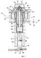
- Fig. 1 is a prior art according to the DE 10 2005 001 744 B3 corresponding strut 10 shown with a telescopic shock absorber 12, a support spring formed by a helical compression spring 14, a balance spring 16 and a height adjustment device 18th
- the strut 10 is articulated as part of a suspension for a motor vehicle on the one hand on the structure 20 via a damper bearing 22 and on the other hand via a rubber-metal sleeve bearing 24 on a control arm 26 as a suspension element of the suspension.
- the suspension spring 14 is firmly supported at its lower end via a spring plate 28 on the damper tube 30 of the shock absorber 12 and is located at its upper end to an axially displaceable spring plate 32 at.
- the damper bearing 22 has a receiving plate 40 which is fixed to the body 20 of the motor vehicle; between the receiving plate 40 and the Bearing 36, the rubber-elastic, annular damping body 42 of the damper bearing 22 is inserted.
- the damper bearing 22 has, inter alia, the task of high-frequency vibrations, which would pass from the roadway on the chassis in the structure 20, to a large extent to eliminate.
- 22 road shocks are mitigated by the damper bearing, z. B. when crossing obstacles, poor roads or potholes.
- D. h. That the design of the damper bearing 22 is designed according to special, progressive characteristics that seek to harden the bearing 22 with increasing travel deliberately. The damper bearing 22 is thus not insignificantly decelerated while driving and thus hardened.
- the height adjustment device 18 is composed essentially of an around the piston rod 38 of the shock absorber 12 and within the balance spring 16 arranged electric motor 44, the rotor 46 drives a rotatably mounted on a fixed inner sleeve 52 threaded spindle 50.
- the threaded spindle 50 interacts with the ball nut 48 of the height adjustment device 18 in such a way that, in the case of an electromotive rotation of the threaded spindle 50, the ball nut 48 permanently connected to the spring plate 32 is displaced in the axial direction a. As a result, the bias of the suspension spring 14 is adjusted accordingly to achieve a level adjustment of the body of the vehicle.
- Fig. 1 illustrated strut 10 may be omitted in the context of the present invention.
- Fig. 1 describes the dynamic loads acting on the strut 10 during driving:
- Fig . 2 to 5 is the strut 10 ', the extent not described in accordance with Fig. 1 can be executed and provided with the same reference numerals, connected via a universal joint 60 with the structure 20 (not shown) of the motor vehicle.
- the universal joint 60 is between the upper damper bearing 22 'and the structure 20 is turned on (see. Fig. 4 and 5 ).
- the universal joint 60 is formed from a radially outer receiving ring 62, which is provided for attachment to the structure 20 with bolts 62 a.
- a radially outer receiving ring 62 Radially within the receiving plate 62 is an annular spider 64 arranged. Again radially within the spider 64 is a housing ring 66 of the damper bearing 22 '.
- the spider 64 of the universal joint 60 is according to the Fig. 5 via respective diametrically opposed pivot bearing (uniformly designated 68) with the receiving ring 62 and the housing ring 66, wherein the axes of rotation 70, 72 (see. Fig. 3 ) 90 degrees offset from each other.
- the one axis of rotation 70 is aligned so that, viewed in plan view, it is aligned parallel to the pivot axis (not shown) of the wheel suspension element or transverse link 26.
- pivot bearings 68 lie in a uniform hinge plane 70, 72, so that, as from the Fig. 4 and 5 can be seen, the housing ring 66, the spider 64 and the receiving ring 62 are arranged nested (low height).
- the pivot bearings 68 are each formed by a in the housing ring 66 (see. Fig. 4 ) or in the spider 64 ( Fig. 5 ) screwed pivot pin 74 having a threaded portion 74 a larger diameter, a hexagon socket (without reference numeral) for a mounting tool and a cylindrical bearing portion 74 b, wherein the bearing portion 74 b each protrudes into a bearing receptacle 76 in the spider 64 or in the receiving plate 62.
- the bearing receptacle 76 is a in the spider 64 ( Fig. 4 ) or in the receiving ring 62 pressed socket.
- a bearing sleeve 75 is pushed.
- the bearing sleeve 75 is clamped in the illustrated installed state with the pivot pin 74, as indicated by the arrows 77.
- the pivot pins 74 are rotationally symmetrically enclosed by the receiving ring 62, the joint cage 64 and the housing ring 66.
- the universal joint 60 can therefore - in contrast to the ball joint solution - withstand a compressive load as well as a tensile load, without that there is a risk of "Ausknexcellentns” Kardangelenk turnover under tensile load.
- the bearing pins 74 are each inserted from radially outside to inside, wherein in the assembly of the universal joint 60 first the spider 64 with the housing ring 66 of the damper bearing 22 'and then the receiving ring 62 is connected to the spider 64.
- the preassembled with the strut 10 'assembly can then be screwed on the receiving ring 62 with the structure 20 of the motor vehicle.
- the strut 10 ' may preferably according to Fig. 1 be executed with a balance spring 16 and a height adjustment device 18.
- the invention is also applicable to struts with only one suspension spring 14 and a telescopic shock absorber 12.
Landscapes
- Engineering & Computer Science (AREA)
- General Engineering & Computer Science (AREA)
- Mechanical Engineering (AREA)
- Vehicle Body Suspensions (AREA)
- Fluid-Damping Devices (AREA)
Claims (8)
- Support de jambe de force du côté de la carrosserie, pour suspensions de roues de véhicules automobiles, comprenant une jambe de force (10) constituée au moins d'un amortisseur télescopique (12) et d'un ressort porteur (14), qui est supportée par le biais d'un palier d'amortisseur (22) sur la carrosserie (20) et par le biais d'un autre palier (24) sur des éléments de suspension de roues (26) du véhicule automobile, une articulation (60) étant prévue entre la carrosserie (20) et la jambe de force (10), l'articulation étant formée par une articulation à cardan (60) avec deux axes de rotation se croisant (70, 72), et l'articulation à cardan (60) étant montée entre la carrosserie (20) du véhicule automobile et le palier d'amortisseur (22'), caractérisé en ce que l'articulation à cardan (60) est intégrée dans une bague de réception (62) du côté de la carrosserie, et une bague de boîtier (66) du palier d'amortisseur (22').
- Support de jambe de force selon la revendication 1, caractérisé en ce qu'entre la bague de réception (62) et la bague de boîtier (66) du palier d'amortisseur (22') est disposé un croisillon de forme annulaire (64), qui est connecté à la bague de réception (62) et à la bague de boîtier (66) par le biais de paliers pivotants (68) à chaque fois diamétralement opposés.
- Support de jambe de force selon la revendication 2, caractérisé en ce que les paliers pivotants (68) de la bague de réception (62) et de la bague de boîtier (66) se trouvent dans un plan d'articulation unitaire (70, 72).
- Support de jambe de force selon l'une quelconque des revendications précédentes, caractérisé en ce que l'un des axes de rotation (70) de l'articulation à cardan (60) est orienté parallèlement à l'axe de pivotement de l'élément de suspension de roue (26) sur lequel est articulée la jambe de force (10').
- Support de jambe de force selon l'une quelconque des revendications 2 à 4, caractérisé en ce que les paliers pivotants (68) sont formés par des boulons de palier (74) vissés dans la bague de réception (62) et/ou dans le croisillon (64), qui sont guidés dans des logements de palier correspondants (76).
- Support de jambe de force selon la revendication 5, caractérisé en ce que les logements de palier (76) sont formés par des coussinets ou des paliers à roulement.
- Support de jambe de force selon la revendication 5 ou 6, caractérisé en ce que les boulons de palier (74) des paliers pivotants (68) sont vissés entre le croisillon (64) et la bague de boîtier (66) dans le croisillon (64) et les boulons de palier (74) des paliers pivotants (68) sont vissés entre la bague de réception (62) et le croisillon (64) dans la bague de réception (62), à chaque fois depuis l'extérieur vers l'intérieur.
- Support de jambe de force selon l'une quelconque des revendications précédentes, caractérisé en ce que la jambe de force (10) présente un réglage de niveau intégré de la carrosserie du véhicule automobile, dans lequel un dispositif de réglage (18) est pourvu d'un mécanisme hélicoïdal à billes disposé autour de l'amortisseur télescopique (12), qui, par le biais d'une broche filetée (50) montée à rotation et d'un écrou à billes (48) monté de manière déplaçable axialement, règle par le biais d'un moteur électrique un ressort Belleville (32) du ressort porteur (14) par rapport à la carrosserie (20).
Applications Claiming Priority (1)
| Application Number | Priority Date | Filing Date | Title |
|---|---|---|---|
| DE102007020022A DE102007020022A1 (de) | 2007-04-28 | 2007-04-28 | Aufbauseitige Federbeinlagerung für Radaufhängungen |
Publications (2)
| Publication Number | Publication Date |
|---|---|
| EP1985475A1 EP1985475A1 (fr) | 2008-10-29 |
| EP1985475B1 true EP1985475B1 (fr) | 2010-06-30 |
Family
ID=39434368
Family Applications (1)
| Application Number | Title | Priority Date | Filing Date |
|---|---|---|---|
| EP08001875A Expired - Fee Related EP1985475B1 (fr) | 2007-04-28 | 2008-02-01 | Stockage d'une jambe de force à ressort du côté du montage pour suspensions de roues |
Country Status (5)
| Country | Link |
|---|---|
| US (1) | US7857335B2 (fr) |
| EP (1) | EP1985475B1 (fr) |
| JP (1) | JP5250865B2 (fr) |
| CN (1) | CN101293471B (fr) |
| DE (2) | DE102007020022A1 (fr) |
Cited By (1)
| Publication number | Priority date | Publication date | Assignee | Title |
|---|---|---|---|---|
| RU2714092C1 (ru) * | 2016-03-24 | 2020-02-11 | Бпв Бергише Ахзен Кг | Устройство подвода для дискового тормоза транспортного средства, а также карданная врашающаяся опора и муфтовое кольцо для него |
Families Citing this family (12)
| Publication number | Priority date | Publication date | Assignee | Title |
|---|---|---|---|---|
| DE102007040734B4 (de) * | 2007-08-29 | 2009-05-07 | Audi Ag | Federbein für eine Radaufhängung von Kraftfahrzeugen |
| DE102008006087A1 (de) * | 2008-01-25 | 2009-07-30 | Thyssenkrupp Bilstein Suspension Gmbh | Federbein mit verstellbarem Federteller |
| DE102009011669A1 (de) | 2009-03-04 | 2009-11-19 | Daimler Ag | Federbein |
| KR101094215B1 (ko) * | 2009-09-07 | 2011-12-14 | 주식회사 만도 | 공기현가장치 |
| US8807574B2 (en) * | 2010-05-14 | 2014-08-19 | Magna Steyr Fahrzeugtechnik Ag & Co Kg | Spring-damper unit for height adjustment of a vehicle |
| US9844993B2 (en) * | 2014-10-31 | 2017-12-19 | TAP Worldwide, LLC | Two-piece adjustable strut spacer |
| CN104842773B (zh) * | 2014-12-19 | 2017-02-22 | 北汽福田汽车股份有限公司 | 悬置结构、悬置安装装置以及车辆 |
| US10503699B2 (en) * | 2016-04-25 | 2019-12-10 | Sap Se | Metadata synchronization in a distrubuted database |
| CN107458151B (zh) * | 2017-08-30 | 2023-03-14 | 安徽安凯汽车股份有限公司 | 全承载公交客车后桥限位装置安装结构 |
| KR102635917B1 (ko) * | 2018-08-29 | 2024-02-08 | 현대자동차주식회사 | 서스펜션용 차고조절장치 |
| DE102018125459A1 (de) * | 2018-10-15 | 2020-04-16 | Bayerische Motoren Werke Aktiengesellschaft | Befestigungsanordnung eines Schwingungsdämpfers |
| DE102019004871A1 (de) | 2019-07-11 | 2020-01-09 | Daimler Ag | Fahrzeugdämpfer |
Family Cites Families (13)
| Publication number | Priority date | Publication date | Assignee | Title |
|---|---|---|---|---|
| US2687099A (en) * | 1947-07-03 | 1954-08-24 | Talgo Patentes | Articulated railway vehicle |
| US2823927A (en) * | 1954-01-07 | 1958-02-18 | Frieda K Schumacher | Torque arm type of a wheel suspension |
| DE1938142U (de) * | 1966-03-07 | 1966-05-12 | Mak Maschb Kiel G M B H | Vorrichtung zum befestigen von schwingungsdampfen, insbesondere fuer schienenfahrzeuge. |
| US3595999A (en) | 1968-12-09 | 1971-07-27 | Martin Alan Cole | Automatic telephone alarm apparatus |
| GB1267838A (en) * | 1969-06-24 | 1972-03-22 | Fuji Heavy Ind Ltd | A front wheel drive vehicle including an independent front suspension system |
| JPS62163811A (ja) * | 1986-01-16 | 1987-07-20 | Toyota Motor Corp | 懸架装置の支持構造 |
| DE3876528T2 (de) * | 1987-07-29 | 1993-04-15 | Mazda Motor | Fahrzeugaufhaengungssystem. |
| DE19960457C2 (de) * | 1999-03-06 | 2001-10-11 | Porsche Ag | Lagerung für ein Dämpferbein oder eine Luftfeder einer Radaufhängung |
| DE10038267B4 (de) | 2000-08-04 | 2009-01-02 | Audi Ag | Vorrichtung zur karosserieseitigen Lagerung eines Federbeines |
| WO2003106245A1 (fr) | 2002-06-18 | 2003-12-24 | Francis Bernard Harries | Direction de vehicule |
| DE102005001742A1 (de) | 2005-01-14 | 2006-03-16 | Zf Friedrichshafen Ag | Federbein mit verstellbarem Federteller |
| DE102005001744B3 (de) | 2005-01-14 | 2006-07-06 | Zf Friedrichshafen Ag | Federträger mit verstellbarem Federteller |
| JP2006220293A (ja) * | 2005-02-14 | 2006-08-24 | Showa Corp | 電磁式緩衝器 |
-
2007
- 2007-04-28 DE DE102007020022A patent/DE102007020022A1/de not_active Withdrawn
-
2008
- 2008-02-01 DE DE502008000855T patent/DE502008000855D1/de active Active
- 2008-02-01 EP EP08001875A patent/EP1985475B1/fr not_active Expired - Fee Related
- 2008-04-04 JP JP2008097647A patent/JP5250865B2/ja not_active Expired - Fee Related
- 2008-04-25 CN CN2008100960087A patent/CN101293471B/zh not_active Expired - Fee Related
- 2008-04-28 US US12/111,042 patent/US7857335B2/en not_active Expired - Fee Related
Cited By (1)
| Publication number | Priority date | Publication date | Assignee | Title |
|---|---|---|---|---|
| RU2714092C1 (ru) * | 2016-03-24 | 2020-02-11 | Бпв Бергише Ахзен Кг | Устройство подвода для дискового тормоза транспортного средства, а также карданная врашающаяся опора и муфтовое кольцо для него |
Also Published As
| Publication number | Publication date |
|---|---|
| CN101293471A (zh) | 2008-10-29 |
| US7857335B2 (en) | 2010-12-28 |
| JP5250865B2 (ja) | 2013-07-31 |
| CN101293471B (zh) | 2011-09-07 |
| US20090003741A1 (en) | 2009-01-01 |
| DE502008000855D1 (de) | 2010-08-12 |
| DE102007020022A1 (de) | 2008-10-30 |
| EP1985475A1 (fr) | 2008-10-29 |
| JP2008273508A (ja) | 2008-11-13 |
Similar Documents
| Publication | Publication Date | Title |
|---|---|---|
| EP1985475B1 (fr) | Stockage d'une jambe de force à ressort du côté du montage pour suspensions de roues | |
| EP2254762B1 (fr) | Suspension de roue pour les roues directrices de véhicules à moteur | |
| EP2443019B1 (fr) | Element suspension de roue pour les roues arriere de vehicules a moteur | |
| DE102010048210B4 (de) | Fahrzeugsitz mit Fluidfeder | |
| EP2342094B1 (fr) | Suspension de roue pour véhicules automobiles | |
| DE4100296C1 (fr) | ||
| EP0944486A1 (fr) | Systeme de suspension pneumatique | |
| EP2135756B1 (fr) | Jambe de force pour suspensions de roues de véhicules automobiles | |
| DE3510335C2 (fr) | ||
| DE4443809A1 (de) | Stabilisatoranordnung für ein Fahrwerk eines Kraftfahrzeugs | |
| DE10204975B4 (de) | Drehgelenk | |
| DE102004002432B4 (de) | Karosserieseitige Lagerung eines Federbeins einer Radaufhängung für Fahrzeuge | |
| DE102005013374B4 (de) | Halterung für einen um eine Schwenkachse schwenkbaren Lenker einer Radaufhängung eines Fahrzeugs | |
| DE102007046219A1 (de) | Stützlager für ein Fahrzeug | |
| DE3233878C2 (fr) | ||
| DE102005011253A1 (de) | Vorrichtung zum längenveränderlichen Verstellen eines Lenkers | |
| WO2007033892A1 (fr) | Ensemble ressort a gaz | |
| EP3153737B1 (fr) | Palier de châssis | |
| DE102007027251A1 (de) | Oberes Verankerungssystem für ein Federbein eines Fahrzeuges | |
| EP2423532B1 (fr) | Douille en caoutchouc d'acier | |
| DE19580267B4 (de) | Anordnung zur Aufhängung eines gefederten Fahrzeug-Fahrerhauses an einem Fahrzeugrahmen | |
| DE3938773C2 (de) | Federbein-Radaufhängung für Kraftfahrzeuge | |
| DE102017211277B4 (de) | Radaufhängung für ein Kraftfahrzeug | |
| DE102009057003A1 (de) | Federbeinanordnung für eine Radaufhängung eines Kraftfahrzeuges | |
| DE3631610A1 (de) | Luftgefederte federbeinanordnung fuer kraftfahrzeuge |
Legal Events
| Date | Code | Title | Description |
|---|---|---|---|
| PUAI | Public reference made under article 153(3) epc to a published international application that has entered the european phase |
Free format text: ORIGINAL CODE: 0009012 |
|
| AK | Designated contracting states |
Kind code of ref document: A1 Designated state(s): AT BE BG CH CY CZ DE DK EE ES FI FR GB GR HR HU IE IS IT LI LT LU LV MC MT NL NO PL PT RO SE SI SK TR |
|
| AX | Request for extension of the european patent |
Extension state: AL BA MK RS |
|
| 17P | Request for examination filed |
Effective date: 20090429 |
|
| 17Q | First examination report despatched |
Effective date: 20090612 |
|
| AKX | Designation fees paid |
Designated state(s): DE FR GB IT |
|
| GRAP | Despatch of communication of intention to grant a patent |
Free format text: ORIGINAL CODE: EPIDOSNIGR1 |
|
| GRAS | Grant fee paid |
Free format text: ORIGINAL CODE: EPIDOSNIGR3 |
|
| GRAA | (expected) grant |
Free format text: ORIGINAL CODE: 0009210 |
|
| STAA | Information on the status of an ep patent application or granted ep patent |
Free format text: STATUS: THE PATENT HAS BEEN GRANTED |
|
| AK | Designated contracting states |
Kind code of ref document: B1 Designated state(s): DE FR GB IT |
|
| REG | Reference to a national code |
Ref country code: GB Ref legal event code: FG4D Free format text: NOT ENGLISH |
|
| REF | Corresponds to: |
Ref document number: 502008000855 Country of ref document: DE Date of ref document: 20100812 Kind code of ref document: P |
|
| PLBE | No opposition filed within time limit |
Free format text: ORIGINAL CODE: 0009261 |
|
| STAA | Information on the status of an ep patent application or granted ep patent |
Free format text: STATUS: NO OPPOSITION FILED WITHIN TIME LIMIT |
|
| 26N | No opposition filed |
Effective date: 20110331 |
|
| REG | Reference to a national code |
Ref country code: DE Ref legal event code: R097 Ref document number: 502008000855 Country of ref document: DE Effective date: 20110330 |
|
| REG | Reference to a national code |
Ref country code: FR Ref legal event code: PLFP Year of fee payment: 9 |
|
| REG | Reference to a national code |
Ref country code: FR Ref legal event code: PLFP Year of fee payment: 10 |
|
| PGFP | Annual fee paid to national office [announced via postgrant information from national office to epo] |
Ref country code: FR Payment date: 20170221 Year of fee payment: 10 Ref country code: DE Payment date: 20170228 Year of fee payment: 10 |
|
| PGFP | Annual fee paid to national office [announced via postgrant information from national office to epo] |
Ref country code: GB Payment date: 20170221 Year of fee payment: 10 |
|
| PGFP | Annual fee paid to national office [announced via postgrant information from national office to epo] |
Ref country code: IT Payment date: 20170228 Year of fee payment: 10 |
|
| REG | Reference to a national code |
Ref country code: DE Ref legal event code: R119 Ref document number: 502008000855 Country of ref document: DE |
|
| GBPC | Gb: european patent ceased through non-payment of renewal fee |
Effective date: 20180201 |
|
| REG | Reference to a national code |
Ref country code: FR Ref legal event code: ST Effective date: 20181031 |
|
| PG25 | Lapsed in a contracting state [announced via postgrant information from national office to epo] |
Ref country code: DE Free format text: LAPSE BECAUSE OF NON-PAYMENT OF DUE FEES Effective date: 20180901 |
|
| PG25 | Lapsed in a contracting state [announced via postgrant information from national office to epo] |
Ref country code: IT Free format text: LAPSE BECAUSE OF NON-PAYMENT OF DUE FEES Effective date: 20180201 Ref country code: GB Free format text: LAPSE BECAUSE OF NON-PAYMENT OF DUE FEES Effective date: 20180201 Ref country code: FR Free format text: LAPSE BECAUSE OF NON-PAYMENT OF DUE FEES Effective date: 20180228 |