EP1983256A1 - Möbelteil mit einer elektrischen Stromschiene - Google Patents
Möbelteil mit einer elektrischen Stromschiene Download PDFInfo
- Publication number
- EP1983256A1 EP1983256A1 EP07425226A EP07425226A EP1983256A1 EP 1983256 A1 EP1983256 A1 EP 1983256A1 EP 07425226 A EP07425226 A EP 07425226A EP 07425226 A EP07425226 A EP 07425226A EP 1983256 A1 EP1983256 A1 EP 1983256A1
- Authority
- EP
- European Patent Office
- Prior art keywords
- track
- furnishing component
- furnishing
- joint member
- articulated joint
- Prior art date
- Legal status (The legal status is an assumption and is not a legal conclusion. Google has not performed a legal analysis and makes no representation as to the accuracy of the status listed.)
- Withdrawn
Links
- 239000004020 conductor Substances 0.000 claims abstract description 25
- 210000002105 tongue Anatomy 0.000 claims description 17
- 238000000034 method Methods 0.000 claims description 3
- 239000003973 paint Substances 0.000 claims description 3
- 230000005540 biological transmission Effects 0.000 claims 1
- 239000011810 insulating material Substances 0.000 description 2
- 230000001681 protective effect Effects 0.000 description 2
- RYGMFSIKBFXOCR-UHFFFAOYSA-N Copper Chemical compound [Cu] RYGMFSIKBFXOCR-UHFFFAOYSA-N 0.000 description 1
- 229910052802 copper Inorganic materials 0.000 description 1
- 239000010949 copper Substances 0.000 description 1
- 230000008878 coupling Effects 0.000 description 1
- 238000010168 coupling process Methods 0.000 description 1
- 238000005859 coupling reaction Methods 0.000 description 1
- 238000009413 insulation Methods 0.000 description 1
- 238000004519 manufacturing process Methods 0.000 description 1
- 239000002184 metal Substances 0.000 description 1
- 229910052751 metal Inorganic materials 0.000 description 1
- 229910052754 neon Inorganic materials 0.000 description 1
- GKAOGPIIYCISHV-UHFFFAOYSA-N neon atom Chemical compound [Ne] GKAOGPIIYCISHV-UHFFFAOYSA-N 0.000 description 1
- 125000006850 spacer group Chemical group 0.000 description 1
Images
Classifications
-
- F—MECHANICAL ENGINEERING; LIGHTING; HEATING; WEAPONS; BLASTING
- F21—LIGHTING
- F21V—FUNCTIONAL FEATURES OR DETAILS OF LIGHTING DEVICES OR SYSTEMS THEREOF; STRUCTURAL COMBINATIONS OF LIGHTING DEVICES WITH OTHER ARTICLES, NOT OTHERWISE PROVIDED FOR
- F21V21/00—Supporting, suspending, or attaching arrangements for lighting devices; Hand grips
- F21V21/14—Adjustable mountings
- F21V21/26—Pivoted arms
-
- F—MECHANICAL ENGINEERING; LIGHTING; HEATING; WEAPONS; BLASTING
- F21—LIGHTING
- F21V—FUNCTIONAL FEATURES OR DETAILS OF LIGHTING DEVICES OR SYSTEMS THEREOF; STRUCTURAL COMBINATIONS OF LIGHTING DEVICES WITH OTHER ARTICLES, NOT OTHERWISE PROVIDED FOR
- F21V21/00—Supporting, suspending, or attaching arrangements for lighting devices; Hand grips
- F21V21/34—Supporting elements displaceable along a guiding element
- F21V21/35—Supporting elements displaceable along a guiding element with direct electrical contact between the supporting element and electric conductors running along the guiding element
Definitions
- the present invention relates to a furnishing component, such as a piece of furniture, or an electric lamp considered here by way of example.
- electric lamps comprise electric cables with an insulating lining which may peel off or even be cut accidentally.
- the latter are usually positioned inside protective/containing structures such as hollow bars or small tubes, this, however, making manufacture of the lamps more complex and costly.
- the main object of the invention is to provide a furnishing component which solves the problems described in a simple manner.
- a furnishing component comprising at least one track of electrically conductive material for conveying electric current provided on its surface.
- one or more tracks of conductive material may consist of a layer of conductive paint or a strip of copper or other electrically conductive material.
- the object of the invention is also achieved by a method for connecting to a power supply source an electric apparatus which is associated with a furnishing component, characterized in that at least one track of electrically conductive material is provided on the surface of the component.
- the furnishing component may be a lamp with a bar provided on its surfaces with a track which, together with the structure of the lamp made of conductive material, allows the flow of electric current.
- the furnishing component may also comprise one or more mechanical articulated joint members which are joined to one or more tracks so as to form an electrical bridge between them.
- the mechanical articulated joint therefore allows both the flow of electric current and articulation of the furnishing component.
- the mechanical articulated joint member may comprise, for each pair of tracks which it connects in series, two conductive parts which are movably joined together and make frictional contact with each other, each conductive part being connected to a respective track.
- hinge-type fastening system for example hinges
- These parts will act as an electrical bridge (jumper) between the tracks.
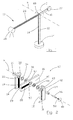
- a lamp 10 according to the invention comprises two separate and parallel vertical bars 12, 14 which are hinged on a pivoting bar 16 by means of a mechanical articulated joint member 60, referred to below more simply as swivel joint.
- the bottom ends of the vertical bars 12, 14 are fixed to a base 24, while the top ends have two coaxial holes 32, 42.
- the pivoting bar 16 has, in a middle longitudinal position, a hole 52 and at the two ends, respectively, a counter-weight 22 and a light source 20 (in Figure 1 shown generically as a cylinder), such as a light bulb or a neon lamp.
- a light source 20 in Figure 1 shown generically as a cylinder, such as a light bulb or a neon lamp.
- Powering of the light source 20 is performed by means of two conductors, each formed by a first and a second track of conductive material which are placed in series electrical connection with each other by the swivel joint 60.
- a conductor comprises a first track 18 and a second track 28, while the other conductor comprises a first track 19 and a second track 29.
- the conductive material is a conductive paint.
- the first tracks 18, 19 are respectively arranged, facing each other, on the surfaces of the opposite sides of the vertical bars 12, 14, as can be seen in Figure 2 .
- the tracks 18, 19 extend from the bottom ends of the bars 12, 14, where they are electrically connected to a power supply source, to the coaxial holes 32, 42 where they are electrically connected to the swivel joint 60.
- the second tracks 28, 29 are respectively arranged on opposite side faces of the pivoting bar 16 and extend from the hole 52 to the end of the pivoting bar 16, where they make contact with the terminals of the light source 20.
- the swivel joint 60 comprises two first bushes 36, 46 which are made of conductive material and each of which is inserted inside a respective annular seat 53 of the bar 28 (in Figure 2 only one seat 53 of a side face is visible).
- the seat 53 is coaxial with the hole 52.
- the bush 36 is rigidly coupled with the pivoting bar 16 and welded or in simple electrical contact with the track 29.
- the bush 46 is welded or in electrical contact with the track 28.
- the swivel joint 60 comprises moreover two second bushes 34, 44 which are inserted respectively inside an annular seat 33 of the vertical bar 14 and inside an annular seat 43 of the vertical bar 12.
- the bush 34 is rigidly coupled with the vertical bar 12 and welded or in simple electrical contact with the track 19.
- the bush 44 is coupled with the vertical bar 14 provided with the track 19.
- the first bushes 36, 46 make frictional contact with the respective second bushes 34, 44 so as to make frictional contact, rotating on top of each other, and also allow the flow of electric current.
- the pivoting bar 16 may rotate about an axis H coinciding with the axis of the holes 32, 42, 52.
- the swivel joint 60 also comprises a pin 54 made of insulating material (for example plastic) with a hole inside which a bar 56 threaded at the ends is arranged. Caps 30, 40 are screwed into the ends of the threaded bar 56 and keep the two lateral bars 12, 14 pressed against the first and second bushes 34, 36, 44, 46 and therefore the pivoting bar 16.
- the pin 54 and the bar 56 may be formed as a single body.
- the electric power supply current is able to flow from one of the tracks 18, 19 to the corresponding track 28, 29 and at the same time the bars 12, 14, and 28 are hinged and are able to rotate relative to each other.
- the electric current passes through (in the following order or in the opposite order) the first track 19, the second bush 34, the first bush 36, the second bush 34 and the second track 29. The same is also applicable to the second conductor.
- Coupling of the bushes or any other parts for connecting the bars or for electrical connection may also be performed by male and female means.
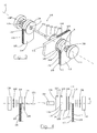
- a lamp which is otherwise similar to the lamp 10, may comprise a different swivel joint - indicated by 160 in Figures 3 and 4 - which again establishes series electrical connection between tracks of conductive material in order to form a continuous conductor.
- the reference numbers for this variant have a prefix "1" for parts which are functionally and/or structurally identical to those of the previous variant.
- a conductor comprising a first track 118 and a second track 128 (visible solely in Figure 4 ), while the other conductor comprises a first track 119 and a second track 129.
- the first tracks 118, 119 are arranged, respectively, on the surfaces of the coplanar sides 113, 115 of vertical bars 112, 114 which are separate from each other and are in the form of a parallelepiped with a rounded end, said bars, together with a pivoting bar 116, in the form of a parallelepiped, forming the structure of the lamp.
- the second tracks 128, 129 are arranged on the two opposite smaller-width sides 131, 141 (in Figure 3 only one side 131 is visible and indicated) of the pivoting bar 116 and extend from the end of the bar 116 corresponding to the light source as far as the point closest to a through-hole 116a in the said bar 116.
- the swivel joint 160 which has a substantially symmetrical structure, comprises two innermost disks 136, 146 and two outer disks 134, 144.
- the disks 134, 136, 144, 146 which are all made of conductive material and have a radius S which is equal to the radius of curvature R of the ends of the bars 112, 114, are centrally holed and coaxial with holes 142 in the end of the vertical bars 112, 114 and the through-hole 116a in the pivoting bar 116.
- a pin 156 made of insulating material (for example plastic) passes through the three bars 112, 114, 116 and the four disks 134, 136, 144, 146.
- the outer disks 134, 144 each have a side bearing against one of the opposite sides of the vertical bars 112, 114.
- Each disk 134, 144 comprises, respectively, two perpendicularly projecting and diametrically opposite tongues 135, 145 (only one of which is visible) which embrace the respective bar 112, 114, the disk of which makes contact.
- the tongues 135 establish electrical contact between the first track 119 and the disk 134, and the tongues 145 establish electrical contact between the first track 118 and the disk 144.
- the tongues 135, 145 also prevent rotation of the disk 134, 144.
- the inner disks 136, 146 make contact, respectively, with the disks 134 and 144 and bear against the bar 116 both with their surface and with a tongue 137, 147 which is formed in the manner of the tongues 135, 145.
- the tongues 137, 147 make electrical contact with the tracks 129, 128, respectively, and rotationally entrain the disks 136, 146 when the bar 116 is displaced.
- the path followed by the electric power supply current is as follows: the first track 119, the tongue 135, the outer disk 134, the inner disk 136, the tongue 137, the track 129, the light source, the track 128, the tongue 147, the inner disk 146, the outer disk 144, the tongue 145 and the track 118.
- Locking in position of the pivoting bar 116 with respect to the two vertical bars 112, 114 is achieved by rotating two knobs 130, 140 which are screwed onto the two ends of a threaded bar 156 passing inside the hole in the pin 154.
- Suitable means such as springs 158, 168, rubber spacers and washers, allow the bar locking operations to be performed by means of the knobs 130, 140.
- the disks 134, 136 and the disks 144, 146 may be rigidly fastened together or formed as a single body.
- the assembly may then be rotated together with the bar 166 and the tongue 145 may rotate along the end edge of the bars 112, 114.
- By sliding a tongue 145 it is possible to make or break contact with the adjacent track 118, 119, thus acting as a sliding switch. In this way it is possible to open or close the electric circuit and thus switch on or off the light source of the lamp, simply by displacing the pivoting bar 116.
- the lamp may comprise, in addition to a pivoting bar, a single vertical bar instead of two bars.
- the tracks may be located on the facing or opposite side surfaces of the two bars.
- the swivel joint may incorporate two bridge-pieces which connect each track of the vertical bar to the respective track of the oscillating bar.
- One or more tracks and/or one or more swivel joints may also be mounted on furnishing components other than a lamp, in order to transmit electric current between parts movable relative to each other.
- a variant may be a piece of furniture, for example a cupboard, in which the hinges of the leaves are configured for example in the manner of the swivel joint 60 or are simple metal bodies (of the known type, commercially available) which allow the flow of electric current from one leaf to the main structure, both provided with tracks made of conductive material and terminating on, and bridged by, the swivel joint.
Landscapes
- Engineering & Computer Science (AREA)
- General Engineering & Computer Science (AREA)
- Pivots And Pivotal Connections (AREA)
Priority Applications (1)
| Application Number | Priority Date | Filing Date | Title |
|---|---|---|---|
| EP07425226A EP1983256A1 (de) | 2007-04-18 | 2007-04-18 | Möbelteil mit einer elektrischen Stromschiene |
Applications Claiming Priority (1)
| Application Number | Priority Date | Filing Date | Title |
|---|---|---|---|
| EP07425226A EP1983256A1 (de) | 2007-04-18 | 2007-04-18 | Möbelteil mit einer elektrischen Stromschiene |
Publications (1)
| Publication Number | Publication Date |
|---|---|
| EP1983256A1 true EP1983256A1 (de) | 2008-10-22 |
Family
ID=38222492
Family Applications (1)
| Application Number | Title | Priority Date | Filing Date |
|---|---|---|---|
| EP07425226A Withdrawn EP1983256A1 (de) | 2007-04-18 | 2007-04-18 | Möbelteil mit einer elektrischen Stromschiene |
Country Status (1)
| Country | Link |
|---|---|
| EP (1) | EP1983256A1 (de) |
Citations (3)
| Publication number | Priority date | Publication date | Assignee | Title |
|---|---|---|---|---|
| DE8607893U1 (de) * | 1986-03-21 | 1987-12-03 | Bartel, Bernhard, 80538 München | Elektrische Einrichtung mit mindestens einer auf einer Fläche lösbar angeordneten elektrischen Verbrauchereinheit |
| WO1990011471A1 (en) * | 1987-09-21 | 1990-10-04 | Kaehoenen Matti | Light fitting system |
| EP1214899A2 (de) * | 2000-07-27 | 2002-06-19 | REHAU AG + Co | Profilleiste |
-
2007
- 2007-04-18 EP EP07425226A patent/EP1983256A1/de not_active Withdrawn
Patent Citations (3)
| Publication number | Priority date | Publication date | Assignee | Title |
|---|---|---|---|---|
| DE8607893U1 (de) * | 1986-03-21 | 1987-12-03 | Bartel, Bernhard, 80538 München | Elektrische Einrichtung mit mindestens einer auf einer Fläche lösbar angeordneten elektrischen Verbrauchereinheit |
| WO1990011471A1 (en) * | 1987-09-21 | 1990-10-04 | Kaehoenen Matti | Light fitting system |
| EP1214899A2 (de) * | 2000-07-27 | 2002-06-19 | REHAU AG + Co | Profilleiste |
Similar Documents
| Publication | Publication Date | Title |
|---|---|---|
| AU597961B2 (en) | Low voltage distribution system with two-conductor track | |
| US9250500B2 (en) | Articulating camera arm and camera assembly comprising same | |
| JP2002500805A (ja) | 照明回路、照明システムの方法と装置、ソケットアセンブリ、ランプ絶縁体アセンブリ、およびその部品 | |
| US10914435B2 (en) | Modular lightbar system and method | |
| DE19849101A1 (de) | Stromschienensystem | |
| EP0281914B1 (de) | Richtungsverstellbare Niedervolt-Leuchte | |
| CN108204558B (zh) | 一种导轨射灯 | |
| AU2014200204B2 (en) | Articulating camera arm and camera assembly comprising same | |
| BRPI0721092B1 (pt) | Chave elétrica para o acoplamento elétrico de um condutor elétrico a um trilho de corrente e instalação de ligação | |
| CA2661475A1 (en) | Termination device impedance assembly | |
| US6530791B1 (en) | Coupling for conductor bars | |
| NL2011791C2 (en) | Electrical connector, connector components of said connector and a device with such a connector component. | |
| EP3115535B1 (de) | Scharnieranordnung für eine isolierte glastür | |
| CA2367930A1 (en) | Live rail support | |
| WO2003085783A3 (en) | Rolling electrical transfer coupling improvements | |
| EP0156290B1 (de) | Leuchte mit schwenkbarem Leuchtenkopf | |
| CN114207954B (zh) | 用于将照明设备电连接到电气轨道的适配器,包括此类适配器和电气轨道的照明系统 | |
| US20230275381A1 (en) | Torque hinge, device having a torque hinge, and use of a torque hinge | |
| AT508337B1 (de) | Beleuchtungsvorrichtung | |
| US507364A (en) | Hanger for electric lamps | |
| US20130214605A1 (en) | Linear automatic transfer switch and switching means | |
| DE102014003251B4 (de) | Leuchtensystem | |
| EP3394375A1 (de) | Drehbare gelenkvorrichtung mit einem elektroanschlusssystem | |
| US277641A (en) | Edward weston | |
| WO1990009687A1 (en) | Electrical power distribution arrangement |
Legal Events
| Date | Code | Title | Description |
|---|---|---|---|
| PUAI | Public reference made under article 153(3) epc to a published international application that has entered the european phase |
Free format text: ORIGINAL CODE: 0009012 |
|
| AK | Designated contracting states |
Kind code of ref document: A1 Designated state(s): AT BE BG CH CY CZ DE DK EE ES FI FR GB GR HU IE IS IT LI LT LU LV MC MT NL PL PT RO SE SI SK TR |
|
| AX | Request for extension of the european patent |
Extension state: AL BA HR MK RS |
|
| AKX | Designation fees paid | ||
| REG | Reference to a national code |
Ref country code: DE Ref legal event code: 8566 |
|
| STAA | Information on the status of an ep patent application or granted ep patent |
Free format text: STATUS: THE APPLICATION IS DEEMED TO BE WITHDRAWN |
|
| 18D | Application deemed to be withdrawn |
Effective date: 20090423 |