EP1983106A2 - Self-propelled construction vehicle - Google Patents
Self-propelled construction vehicle Download PDFInfo
- Publication number
- EP1983106A2 EP1983106A2 EP20080154152 EP08154152A EP1983106A2 EP 1983106 A2 EP1983106 A2 EP 1983106A2 EP 20080154152 EP20080154152 EP 20080154152 EP 08154152 A EP08154152 A EP 08154152A EP 1983106 A2 EP1983106 A2 EP 1983106A2
- Authority
- EP
- European Patent Office
- Prior art keywords
- driver
- station
- construction machine
- machine according
- frame
- Prior art date
- Legal status (The legal status is an assumption and is not a legal conclusion. Google has not performed a legal analysis and makes no representation as to the accuracy of the status listed.)
- Granted
Links
- 238000010276 construction Methods 0.000 title claims abstract description 31
- 238000003801 milling Methods 0.000 claims description 46
- 238000012544 monitoring process Methods 0.000 claims description 7
- 230000009194 climbing Effects 0.000 claims description 6
- 239000003381 stabilizer Substances 0.000 claims description 6
- 239000000463 material Substances 0.000 claims description 5
- 238000012545 processing Methods 0.000 claims description 2
- 101100390736 Danio rerio fign gene Proteins 0.000 description 3
- 101100390738 Mus musculus Fign gene Proteins 0.000 description 3
- 230000007935 neutral effect Effects 0.000 description 2
- 230000001419 dependent effect Effects 0.000 description 1
- 238000013461 design Methods 0.000 description 1
- 238000011161 development Methods 0.000 description 1
- 238000006073 displacement reaction Methods 0.000 description 1
- 230000000694 effects Effects 0.000 description 1
- 230000001681 protective effect Effects 0.000 description 1
- 239000003583 soil stabilizing agent Substances 0.000 description 1
Images


Classifications
-
- E—FIXED CONSTRUCTIONS
- E01—CONSTRUCTION OF ROADS, RAILWAYS, OR BRIDGES
- E01C—CONSTRUCTION OF, OR SURFACES FOR, ROADS, SPORTS GROUNDS, OR THE LIKE; MACHINES OR AUXILIARY TOOLS FOR CONSTRUCTION OR REPAIR
- E01C23/00—Auxiliary devices or arrangements for constructing, repairing, reconditioning, or taking-up road or like surfaces
- E01C23/06—Devices or arrangements for working the finished surface; Devices for repairing or reconditioning the surface of damaged paving; Recycling in place or on the road
- E01C23/08—Devices or arrangements for working the finished surface; Devices for repairing or reconditioning the surface of damaged paving; Recycling in place or on the road for roughening or patterning; for removing the surface down to a predetermined depth high spots or material bonded to the surface, e.g. markings; for maintaining earth roads, clay courts or like surfaces by means of surface working tools, e.g. scarifiers, levelling blades
- E01C23/085—Devices or arrangements for working the finished surface; Devices for repairing or reconditioning the surface of damaged paving; Recycling in place or on the road for roughening or patterning; for removing the surface down to a predetermined depth high spots or material bonded to the surface, e.g. markings; for maintaining earth roads, clay courts or like surfaces by means of surface working tools, e.g. scarifiers, levelling blades using power-driven tools, e.g. vibratory tools
- E01C23/088—Rotary tools, e.g. milling drums
-
- B—PERFORMING OPERATIONS; TRANSPORTING
- B62—LAND VEHICLES FOR TRAVELLING OTHERWISE THAN ON RAILS
- B62D—MOTOR VEHICLES; TRAILERS
- B62D33/00—Superstructures for load-carrying vehicles
- B62D33/06—Drivers' cabs
- B62D33/063—Drivers' cabs movable from one position into at least one other position, e.g. tiltable, pivotable about a vertical axis, displaceable from one side of the vehicle to the other
- B62D33/0636—Drivers' cabs movable from one position into at least one other position, e.g. tiltable, pivotable about a vertical axis, displaceable from one side of the vehicle to the other displaceable along a linear path
-
- E—FIXED CONSTRUCTIONS
- E01—CONSTRUCTION OF ROADS, RAILWAYS, OR BRIDGES
- E01C—CONSTRUCTION OF, OR SURFACES FOR, ROADS, SPORTS GROUNDS, OR THE LIKE; MACHINES OR AUXILIARY TOOLS FOR CONSTRUCTION OR REPAIR
- E01C21/00—Apparatus or processes for surface soil stabilisation for road building or like purposes, e.g. mixing local aggregate with binder
-
- E—FIXED CONSTRUCTIONS
- E01—CONSTRUCTION OF ROADS, RAILWAYS, OR BRIDGES
- E01C—CONSTRUCTION OF, OR SURFACES FOR, ROADS, SPORTS GROUNDS, OR THE LIKE; MACHINES OR AUXILIARY TOOLS FOR CONSTRUCTION OR REPAIR
- E01C23/00—Auxiliary devices or arrangements for constructing, repairing, reconditioning, or taking-up road or like surfaces
- E01C23/01—Devices or auxiliary means for setting-out or checking the configuration of new surfacing, e.g. templates, screed or reference line supports; Applications of apparatus for measuring, indicating, or recording the surface configuration of existing surfacing, e.g. profilographs
-
- E—FIXED CONSTRUCTIONS
- E01—CONSTRUCTION OF ROADS, RAILWAYS, OR BRIDGES
- E01C—CONSTRUCTION OF, OR SURFACES FOR, ROADS, SPORTS GROUNDS, OR THE LIKE; MACHINES OR AUXILIARY TOOLS FOR CONSTRUCTION OR REPAIR
- E01C23/00—Auxiliary devices or arrangements for constructing, repairing, reconditioning, or taking-up road or like surfaces
- E01C23/06—Devices or arrangements for working the finished surface; Devices for repairing or reconditioning the surface of damaged paving; Recycling in place or on the road
- E01C23/065—Recycling in place or on the road, i.e. hot or cold reprocessing of paving in situ or on the traffic surface, with or without adding virgin material or lifting of salvaged material; Repairs or resurfacing involving at least partial reprocessing of the existing paving
-
- E—FIXED CONSTRUCTIONS
- E01—CONSTRUCTION OF ROADS, RAILWAYS, OR BRIDGES
- E01C—CONSTRUCTION OF, OR SURFACES FOR, ROADS, SPORTS GROUNDS, OR THE LIKE; MACHINES OR AUXILIARY TOOLS FOR CONSTRUCTION OR REPAIR
- E01C23/00—Auxiliary devices or arrangements for constructing, repairing, reconditioning, or taking-up road or like surfaces
- E01C23/06—Devices or arrangements for working the finished surface; Devices for repairing or reconditioning the surface of damaged paving; Recycling in place or on the road
- E01C23/12—Devices or arrangements for working the finished surface; Devices for repairing or reconditioning the surface of damaged paving; Recycling in place or on the road for taking-up, tearing-up, or full-depth breaking-up paving, e.g. sett extractor
- E01C23/122—Devices or arrangements for working the finished surface; Devices for repairing or reconditioning the surface of damaged paving; Recycling in place or on the road for taking-up, tearing-up, or full-depth breaking-up paving, e.g. sett extractor with power-driven tools, e.g. oscillated hammer apparatus
- E01C23/127—Devices or arrangements for working the finished surface; Devices for repairing or reconditioning the surface of damaged paving; Recycling in place or on the road for taking-up, tearing-up, or full-depth breaking-up paving, e.g. sett extractor with power-driven tools, e.g. oscillated hammer apparatus rotary, e.g. rotary hammers
-
- E—FIXED CONSTRUCTIONS
- E01—CONSTRUCTION OF ROADS, RAILWAYS, OR BRIDGES
- E01C—CONSTRUCTION OF, OR SURFACES FOR, ROADS, SPORTS GROUNDS, OR THE LIKE; MACHINES OR AUXILIARY TOOLS FOR CONSTRUCTION OR REPAIR
- E01C2301/00—Machine characteristics, parts or accessories not otherwise provided for
- E01C2301/30—Cabin details
Definitions
- the invention relates to a self-propelled construction machine, in particular road milling machine, recycler or a stabilizer according to the preamble of claim 1.
- Such road milling machines are for example from the WO02 / 01005 known.
- a road milling machine has a chassis supported by a chassis and has substantially vertically extending lateral outer walls.
- a milling drum is mounted for processing a ground or traffic surface.
- the road milling machine is further provided with a control station with a control and display panel and a seat for the driver.
- a stabilizer is out of the DE 103 57 074 known.
- the seat of the driver is preferably arranged on the so-called zero side of the road milling machine, on which the milling drum with its front side next along an obstacle, such as a curb or a guard rail, can be passed.
- the end face of the milling drum can not be moved so close to an obstacle due to the drive device.
- the driver can observe from his zero-side seat the outer edge of the machine opposite the neutral side by means of outside mirrors.
- the invention is therefore the object of developing a construction machine of the type mentioned in such a way that the visibility for the driver to be improved, so that the operation of a construction machine is possible both in maneuvering as well as in work without any additional assistants.
- the invention provides advantageously that the driver's cab is movable transversely to the direction of travel, and that the seat for the driver is integrated into the driver's cab, which is movable beyond the lateral outer walls of the machine frame to the outside, the machine frame a transverse to the direction of travel has effective guidance for the driver's station and the leadership does not or only slightly beyond the lateral outer walls.
- the driver's cab is only partially movable beyond the lateral outer walls, it being sufficient that the driver in the driver's cab can observe the lateral outer wall and the area next to the outer wall.
- the driver can drive out with his seat on the lateral outer walls on both sides of the construction machine, so that he can observe the outside of the machine optimally in shunting and milling operation. Even in the case of an obstacle such as a street lamp, the driver briefly move his driver's cab inside until the construction machine has passed the obstacle.
- the driver's cab can be pivotable about a vertical axis beyond the lateral outer walls at least in the outer end positions of the at least one guide. In this way, the driver can be brought into an optimal position for observing the shunting and milling operation of the machine.
- control and display panel is integrated in the movable operator's station. In this way, the driver does not have to leave his seat to operate the machine or to read gauges.
- a column fastened to the movable driver's station carries the operating and display console at an adjustable distance from the vehicle driver.
- the control and display panel can be ergonomically adapted to the respective driver.
- the height of the seat surface of the seat or the height of the floor space in the driver's station is adjustable so that the eye level when seated corresponds substantially to the eye level of the vehicle driver standing up. In this way it is ensured that the driver has the same overview of the vehicle while sitting - as standing - has.
- the seat has armrests, with controls for the machine control can be arranged in extension of an armrest of the seat.
- the driver's station is preferably surrounded by a weather protection device, which is movable together with the driver's cab.
- the weather protection device can consist of a cabin.
- the cabin is preferably collapsible for transport or retractable or foldable, so that the maximum transport dimension of the road milling machine can be kept low when transported on a low loader for bridge underpasses.
- the cabin for example, can be folded around an axis running parallel to the direction of travel if its width transversely to the direction of travel is considerably narrower than its height.
- the control and display panel has control, operating and display elements for driving and maneuvering, milling and monitoring of the milling operation.
- Climbing aids for the driver can be arranged on the lateral outer walls, which are automatically pivotable to reduce the minimum distance of the road milling machine from obstacles to a position in which they rest tightly against the outer wall.
- These climbing aids e.g. Ladders with railings can be applied electrically or hydraulically by remote control without manual operation or assistance by auxiliary persons to the outer wall of the road milling machine, so that the road milling machine can be brought as close as possible to obstacles especially on the zero side.
- pivotable mirrors can be provided which are automatically pivotable to reduce the minimum distance of the road milling machine from obstacles to a position in which they do not protrude laterally or only slightly beyond the outer wall.
- the driver's station may have a vertical pivot axis which extends between the seat and the control and display panel, preferably centrally between the seat and the control and display panel. In this way, the driver's seat performs a pivotal movement about this vertical pivot axis, which is preferably orthogonal to the machine frame.
- the driver's seat can also be rotatable with the driver's cab or independently of the driver's cab, so that the reversing operation is also made easier for the driver.
- a rotation angle of 180 ° is sufficient, whereby a larger angle of rotation may be advantageous.
- the pivoting movement about the vertical pivot axis of the driver's station is released only in the outer end positions of the seat unit at the ends of the rail guide.
- the seat for the driver in the outer end positions of the driver's cab at the ends of the rail guide is automatically pivoted outwards. This means that the driver does not have to operate any operating or control elements in order to reach an optimum sitting position for observing the road surface to be machined, the steering angle, a dipstick and the markings on the road surface.
- the seat or the driver's cab and / or the cabin can be raised to a raised position for the driving and maneuvering operations.
- the driver's station can be arranged in front of the machine frame and / or the chassis, in particular in the case of a recycler or stabilizer in the direction of travel.
- the driver's station can be movably mounted on a pivoting frame of the machine frame and can be raised and lowered by means of the pivoting frame.
- the transverse guide for the driver's position is arranged on the pivot frame of the machine frame.
- the swivel frame is preferably articulated parallelogram on the machine frame, so that the driver's cab or the cabin is moved parallel when raising or lowering.
- a controller automatically compensates for a transverse and / or longitudinal inclination of the machine frame in such a way that the driver's station essentially remains in the horizontal.
- the pivoting frame projects with respect to the driver's cab in the vertical direction and / or transversely to the direction of travel such that it forms a rollover protection.
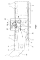
- Fig. 1 shows a road milling machine 1 for milling ground or traffic surfaces 8 in the embodiment of a front-loading road milling machine.
- the road milling machine 1 has a chassis 2 with, for example, four track drives 3, which carries the machine frame 4 of the road milling machine 1. It is understood that the chain drives 3 can be completely or partially substituted by wheel drives.
- a milling drum 6 is mounted, which extends transversely to the direction of travel. The adjustment of the milling depth is preferably carried out with the help of the height adjustment of the crawler tracks 3 via lifting columns 7.
- the in Fig. 1 Road milling machine 1 shown is also called FrontladerStra Tofräse referred to as they can transport the milled material in the direction of travel forward on a transport vehicle.
- a first transport device 9 consisting of a conveyor belt is arranged, which preferably transfers the milled material to a second transport device 11 consisting of a conveyor belt.
- the machine frame 4 has substantially vertically extending lateral outer walls 5.
- a driver's station 10 is arranged with a control and display panel 12 and a seat 14 for the driver.
- the seat 14 and the control and display panel 12 are integrated in the transversely movable to the direction of travel station 10.
- the driver's station 10 can be moved outward beyond the lateral outer walls 5 of the machine frame 4 on a guide 18, preferably a rail guide, connected to the machine frame 4.
- the rail guide 18 is preferably not laterally over the outer walls 5, wherein nevertheless the driver's station 10, as best of the FIGS. 2 and 3 can be seen almost to its center on the lateral outer walls 5 is moved beyond.
- the guide 18 may extend in a horizontal plane substantially transversely to the direction of travel linear or slightly curved or consist of a parallel guide in which the driver's cab is moved in parallel.
- the seat 14 for the driver is rotatable. It is preferably provided that the seat 14 is pivotable together with an operating and display panel 12 about a vertical axis 32 within the driver's station 10.
- the integrated in the movable operator's cab 10 control and display console 12 is this attached to a column 20 at an adjustable distance from the driver and is pivotable about the vertical axis 32 with the seat 14 or independently thereof.
- the seat 14 may be adjustable in height with respect to its seat so that the eye level of the driver sitting substantially equal to the eye level standing in the driver's seat 10.
- the seat 14 may include armrests 22 provided with the machine control controls 24.
- the driver's station 10 is surrounded by a cabin 26 as a weather protection device.
- the cab In the middle position of the cab 26 between the outer walls 5, the cab is lowered relative to the machine frame 4, such that the upper edge of the cab 26 is flush with the machine elements mounted in front of and behind the cab 26 and fastened to the machine frame 4.
- the cabin 26 is in a transport position in order to keep the construction height low when transporting the road milling machine 1 on a low loader.
- the cab may be collapsible or pivotal about a horizontal axis parallel to the direction of travel when the cab 26 is narrow compared to its height.
- climbing aids 28 may be arranged in the form of ladders with handrails, which, when the driver is in the driver's cab 10, by means of drives in the direction of the outer wall 5 can be pivoted so that they are as flat as possible at the Outside wall 5 abut.
- the climbing aids are preferably arranged on the side opposite the zero side of the road milling machine 1, on which the belt drive 15 for the milling drum 6 is arranged.
- the ascent aids can also be arranged on the neutral side of the road milling machine 1.
- the zero side of the machine is the side on which the end face of the milling drum 6 ends very close to the outer wall 5 and on which is not the belt drive 15, so that on the null side of the machine a near-edge or near-obstacle milling is possible.
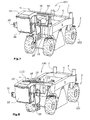
- FIGS. 7 to 10 show a soil stabilizer / recycler 100.
- the machine frame 4 can be supported by lifting columns of a chassis 2, which preferably has wheels 103.
- the driver's station 10 is located in such a construction machine in front of the machine frame 4 and also in front of the chassis 2.
- the driver's station surrounded by a cabin 26 10, which is connected via a pivot frame 16 of the machine frame 4 with the machine frame 4.
- the front in the direction of travel part of the swing frame 16 at the same time forms the guide 18 for the transverse to the direction of travel cabin 26th
- a climbing aid 28 may be attached.
- the Fig. 7 shows the swing frame 16 of the machine frame 4, which is connected via handlebar 102,104 parallelogram with the machine frame 4.
- the parallelogram articulation of the swing frame 16 it is possible to move the operator's cab 10 from a lower position to an upper position and back in parallel without changing the inclination of the cab 26 to a vertical plane transverse to the direction of travel.
- the inclination can also be adjusted by suitable design of the parallelogram linkage or by means of additional devices 108 in pitch and / or bank ( Fig. 10 ).
- arcuate guides 18 may be provided on the upper and / or lower crossbar of the pivot arm 16, which allow lateral displacement of the operator's cab 10 transverse to the direction of travel.
- the Fig. 7 shows a maximum external position of the operator's cab 10, in which the raised cabin 26 protrudes from the one lateral outer wall 5.
- Fig. 8 shows an alternative guide 18 with parallelogram arranged handlebars 110 and a lowered cabin 26th
- the upper crossbar of the swing frame 16 extends over the entire width of the machine frame 4 and can also project in the height direction over the roof of the cabin 26 upwards.
- the swing frame 16 can serve as a rollover protection (Roll Over Protective Structure, ROPS).
- ROPS Roll Over Protective Structure
- a plurality of pivotable mirrors 32 can be arranged, which can be operated by means of drive means of the driver, so that no additional people for these activities are necessary.
- the cabin 26 can be moved to a particularly raised position for shunting or working operation.
- 1 video surveillance devices are arranged at several points of the construction machine.
- a video camera 34 for monitoring the material ejection from the front conveyor belt 11 to a means of transport, such as a truck.
- a video camera 38 for monitoring the rear area may be provided.
- video cameras 36 may be arranged, which allow the observation of the left and right side of the machine in the forward direction along the outer walls 5.
- a video camera 40 can be arranged at the front end of the machine frame 4, which can observe the area in front of the milling drum 6 of the construction machine.
- the described construction machines can be operated by a driver without an assistant, since the driver can perform all machine functions without having to rely on the help of an assistant and without having to leave the driver's seat 10. Due to the video surveillance with the help of the video cameras 34 to 40 and the display of images on the control and display panel 12 and the material transport to a truck in the case of a road milling machine and the maneuvering when starting the construction machine 1 on a low loader by the driver without auxiliary person performed become.
Landscapes
- Engineering & Computer Science (AREA)
- Architecture (AREA)
- Civil Engineering (AREA)
- Structural Engineering (AREA)
- Mining & Mineral Resources (AREA)
- Mechanical Engineering (AREA)
- Transportation (AREA)
- Combustion & Propulsion (AREA)
- Chemical & Material Sciences (AREA)
- Road Paving Machines (AREA)
- Body Structure For Vehicles (AREA)
- Component Parts Of Construction Machinery (AREA)
- Road Repair (AREA)
- Seats For Vehicles (AREA)
- Fittings On The Vehicle Exterior For Carrying Loads, And Devices For Holding Or Mounting Articles (AREA)
- Rear-View Mirror Devices That Are Mounted On The Exterior Of The Vehicle (AREA)
- Disintegrating Or Milling (AREA)
- Shovels (AREA)
Abstract
Description
Die Erfindung betrifft eine selbstfahrende Baumaschine, insbesondere Straßenfräsmaschine, Recycler oder einen Stabilisierer nach dem Oberbegriff des Anspruchs 1.The invention relates to a self-propelled construction machine, in particular road milling machine, recycler or a stabilizer according to the preamble of
Derartige Straßenfräsmaschinen sind beispielsweise aus der
Bei Rückwärtsfahrt muss sich der Fahrzeugführer umdrehen. Der Sitz des Fahrzeugführers ist vorzugsweise auf der sogenannten Nullseite der Straßenfräsmaschine angeordnet, an der die Fräswalze mit ihrer Stirnseite am nächsten entlang eines Hindernisses, z.B. einer Bordsteinkante oder einer Leitplanke, vorbeigeführt werden kann.When reversing the driver has to turn around. The seat of the driver is preferably arranged on the so-called zero side of the road milling machine, on which the milling drum with its front side next along an obstacle, such as a curb or a guard rail, can be passed.
Auf der der Nullseite gegenüberliegenden Seite kann die Stirnseite der Fräswalze aufgrund der Antriebseinrichtung nicht so nah an einem Hindernis vorbeigeführt werden.On the side opposite the null side, the end face of the milling drum can not be moved so close to an obstacle due to the drive device.
Der Fahrzeugführer kann von seinem auf der Nullseite angeordnetem Sitz aus die der Nullseite gegenüberliegende Außenkante der Maschine mit Hilfe von Außenspiegeln beobachten.The driver can observe from his zero-side seat the outer edge of the machine opposite the neutral side by means of outside mirrors.
Aufgrund der eingeschränkten Sicht und Beobachtungsmöglichkeiten ist der Fahrzeugführer auf einen begleitenden Helfer angewiesen, der ihn insbesondere im Rangierbetrieb und im Fräsbetrieb unterstützt. Insbesondere im Fräsbetrieb ergeben sich dann allerdings sehr lange Zeitperioden, in denen der Helfer nicht beschäftigt ist.Due to the limited visibility and observation options, the driver is dependent on an accompanying helper who supports him especially in shunting and in milling operation. However, especially in milling then arise very long periods of time in which the helper is not busy.
Der Erfindung liegt daher die Aufgabe zugrunde eine Baumaschine der eingangs genannten Art derart weiterzubilden, dass die Sichtverhältnisse für den Fahrzeugführer verbessert werden, so dass der Betrieb einer Baumaschine sowohl im Rangierbetrieb als auch im Arbeitsbetrieb ohne weitere Hilfspersonen möglich ist.The invention is therefore the object of developing a construction machine of the type mentioned in such a way that the visibility for the driver to be improved, so that the operation of a construction machine is possible both in maneuvering as well as in work without any additional assistants.
Zur Lösung dieser Aufgabe dienen die Merkmale des Anspruchs 1.To solve this problem serve the features of
Die Erfindung sieht in vorteilhafter Weise vor, dass der Fahrerstand quer zur Fahrtrichtung verfahrbar ist, und dass der Sitz für den Fahrzeugführer in den Fahrerstand integriert ist, der über die seitlichen Außenwände des Maschinenrahmens hinaus nach Außen verfahrbar ist, wobei der Maschinenrahmen eine quer zur Fahrtrichtung wirkende Führung für den Fahrerstand aufweist und die Führung nicht oder nur geringfügig über die seitlichen Außenwände übersteht. Der Fahrerstand ist nur teilweise über die seitlichen Außenwände hinaus verfahrbar, wobei es genügt, dass der Fahrzeugführer in dem Fahrerstand die seitliche Außenwand und den Bereich neben der Außenwand beobachten kann.The invention provides advantageously that the driver's cab is movable transversely to the direction of travel, and that the seat for the driver is integrated into the driver's cab, which is movable beyond the lateral outer walls of the machine frame to the outside, the machine frame a transverse to the direction of travel has effective guidance for the driver's station and the leadership does not or only slightly beyond the lateral outer walls. The driver's cab is only partially movable beyond the lateral outer walls, it being sufficient that the driver in the driver's cab can observe the lateral outer wall and the area next to the outer wall.
Nach der Erfindung kann der Fahrzeugführer mit seinem Sitz über die seitlichen Außenwände hinaus auf beiden Seiten der Baumaschine herausfahren, so dass er die Außenseiten der Maschine im Rangier- und Fräsbetrieb optimal beobachten kann. Auch im Falle eines Hindernisses z.B. einer Straßenlaterne kann der Fahrzeugführer seinen Fahrerstand kurzfristig nach innen verschieben, bis die Baumaschine das Hindernis passiert hat.According to the invention, the driver can drive out with his seat on the lateral outer walls on both sides of the construction machine, so that he can observe the outside of the machine optimally in shunting and milling operation. Even in the case of an obstacle such as a street lamp, the driver briefly move his driver's cab inside until the construction machine has passed the obstacle.
Der Fahrerstand kann zumindest in den äußeren Endpositionen der mindestens einen Führung jenseits der seitlichen Außenwände um eine vertikale Achse schwenkbar sein. Auf diese Weise kann der Fahrzeugführer in eine für die Beobachtung des Rangier- und Fräsbetriebs der Maschine optimale Position gebracht werden.The driver's cab can be pivotable about a vertical axis beyond the lateral outer walls at least in the outer end positions of the at least one guide. In this way, the driver can be brought into an optimal position for observing the shunting and milling operation of the machine.
Vorzugsweise ist das Bedien- und Anzeigepult in den verfahrbaren Fahrerstand integriert. Auf diese Weise muss der Fahrzeugführer seinen Sitz zum Bedienen der Maschine, oder zum Ablesen von Anzeigeinstrumenten nicht verlassen.Preferably, the control and display panel is integrated in the movable operator's station. In this way, the driver does not have to leave his seat to operate the machine or to read gauges.
Nach einer vorteilhaften Weiterbildung ist vorgesehen, dass eine an den verfahrbaren Fahrerstand befestigte Säule das Bedien- und Anzeigepult in einem einstellbaren Abstand von dem Fahrzeugführer trägt. Auf diese Weise kann das Bedien- und Anzeigepult ergonomisch an den jeweiligen Fahrzeugführer angepasst werden.According to an advantageous development, it is provided that a column fastened to the movable driver's station carries the operating and display console at an adjustable distance from the vehicle driver. In this way, the control and display panel can be ergonomically adapted to the respective driver.
Nach einem bevorzugten Ausführungsbeispiel ist die Höhe der Sitzfläche des Sitzes oder die Höhe der Standfläche im Fahrerstand derart einstellbar, dass die Augenhöhe im Sitzen im Wesentlichen der Augenhöhe des Fahrzeugführers im Stehen entspricht. Auf diese Weise ist gewährleistet, dass der Fahrzeugführer auch im Sitzen die gleiche Übersicht über das Fahrzeug - wie im Stehen - besitzt.According to a preferred embodiment, the height of the seat surface of the seat or the height of the floor space in the driver's station is adjustable so that the eye level when seated corresponds substantially to the eye level of the vehicle driver standing up. In this way it is ensured that the driver has the same overview of the vehicle while sitting - as standing - has.
Der Sitz weist Armlehnen auf, wobei Bedienelemente für die Maschinensteuerung in Verlängerung einer Armlehne des Sitzes angeordnet sein können.The seat has armrests, with controls for the machine control can be arranged in extension of an armrest of the seat.
Der Fahrerstand ist vorzugsweise von einer Wetterschutzeinrichtung umgeben, die gemeinsam mit dem Fahrerstand verfahrbar ist.The driver's station is preferably surrounded by a weather protection device, which is movable together with the driver's cab.
Dabei kann die Wetterschutzeinrichtung aus einer Kabine bestehen.The weather protection device can consist of a cabin.
Die Kabine ist zum Transport vorzugsweise zusammenfaltbar oder versenkbar oder umklappbar, damit die maximale Transportabmessung der Straßenfräsmaschine bei einem Transport auf einem Tieflader für Brückenunterführungen gering gehalten werden kann. Die Kabine ist beispielsweise um eine parallel zur Fahrtrichtung verlaufende Achse umklappbar, wenn ihre Breite quer zur Fahrtrichtung erheblich schmaler als ihre Höhe ist.The cabin is preferably collapsible for transport or retractable or foldable, so that the maximum transport dimension of the road milling machine can be kept low when transported on a low loader for bridge underpasses. The cabin, for example, can be folded around an axis running parallel to the direction of travel if its width transversely to the direction of travel is considerably narrower than its height.
Das Bedien- und Anzeigepult weist Steuerungs-, Bedien- und Anzeigelemente für den Fahr- und Rangierbetrieb, den Fräsbetrieb und die Überwachung des Fräsbetriebes auf.The control and display panel has control, operating and display elements for driving and maneuvering, milling and monitoring of the milling operation.
An den seitlichen Außenwänden können Aufstiegshilfen für den Fahrzeugführer angeordnet sein, die zur Verringerung des Mindestabstandes der Straßenfräsmaschine von Hindernissen automatisch in eine Position verschwenkbar sind, in der sie eng an der Außenwand anliegen. Diese Aufstiegshilfen, z.B. Leitern mit Geländern, können elektrisch oder hydraulisch fernbedienbar ohne manuelle Betätigung oder Hilfestellung durch Hilfspersonen an die Außenwand der Straßenfräsmaschine angelegt werden, so dass die Straßenfräsmaschine insbesondere auf der Nullseite möglichst nah an Hindernisse herangeführt werden kann.Climbing aids for the driver can be arranged on the lateral outer walls, which are automatically pivotable to reduce the minimum distance of the road milling machine from obstacles to a position in which they rest tightly against the outer wall. These climbing aids, e.g. Ladders with railings can be applied electrically or hydraulically by remote control without manual operation or assistance by auxiliary persons to the outer wall of the road milling machine, so that the road milling machine can be brought as close as possible to obstacles especially on the zero side.
Des weiteren können schwenkbare Spiegel vorgesehen sein, die zur Verringerung des Mindestabstandes der Straßenfräsmaschine von Hindernissen automatisch in eine Position schwenkbar sind, in der sie nicht oder nur geringfügig über die Außenwand seitlich überstehen.Furthermore, pivotable mirrors can be provided which are automatically pivotable to reduce the minimum distance of the road milling machine from obstacles to a position in which they do not protrude laterally or only slightly beyond the outer wall.
Der Fahrerstand kann eine vertikale Schwenkachse aufweisen, die zwischen dem Sitz und dem Bedien- und Anzeigepult, vorzugsweise mittig zwischen dem Sitz und dem Bedien- und Anzeigepult verläuft. Auf diese Weise führt der Sitz des Fahrzeugführers eine Schwenkbewegung um diese vorzugsweise orthogonal zu dem Maschinenrahmen verlaufende vertikale Schwenkachse aus.The driver's station may have a vertical pivot axis which extends between the seat and the control and display panel, preferably centrally between the seat and the control and display panel. In this way, the driver's seat performs a pivotal movement about this vertical pivot axis, which is preferably orthogonal to the machine frame.
Der Sitz des Fahrzeugführers kann auch mit dem Fahrerstand oder unabhängig von dem Fahrerstand drehbar sein, so dass auch der Rückfahrbetrieb für den Fahrzeugführer erleichtert ist. Vorzugsweise ist ein Drehwinkel von 180° ausreichend, wobei auch ein größerer Drehwinkel vorteilhaft sein kann.The driver's seat can also be rotatable with the driver's cab or independently of the driver's cab, so that the reversing operation is also made easier for the driver. Preferably, a rotation angle of 180 ° is sufficient, whereby a larger angle of rotation may be advantageous.
Vorzugsweise ist die Schwenkbewegung um die vertikale Schwenkachse des Fahrerstandes erst in den äußeren Endpositionen der Sitzeinheit an den Enden der Schienenführung freigegeben.Preferably, the pivoting movement about the vertical pivot axis of the driver's station is released only in the outer end positions of the seat unit at the ends of the rail guide.
Dabei kann vorgesehen sein, dass der Sitz für den Fahrzeugführer in den äußeren Endpositionen des Fahrerstandes an den Enden der Schienenführung automatisch nach außen verschwenkbar ist. Dies bedeutet, dass der Fahrzeugführer keine Bedien- oder Steuerelemente betätigen muss, um in eine optimale Sitzposition zur Beobachtung der zu bearbeitenden Straßenoberfläche, des Lenkeinschlags, eines Peilstabes und der Markierungen auf der Straßenoberfläche zu gelangen.It can be provided that the seat for the driver in the outer end positions of the driver's cab at the ends of the rail guide is automatically pivoted outwards. This means that the driver does not have to operate any operating or control elements in order to reach an optimum sitting position for observing the road surface to be machined, the steering angle, a dipstick and the markings on the road surface.
Der Sitz oder der Fahrerstand und/oder die Kabine können für den Fahr- und Rangierbetrieb in eine angehobene Position anhebbar sein.The seat or the driver's cab and / or the cabin can be raised to a raised position for the driving and maneuvering operations.
Der Fahrerstand kann insbesondere im Falle eines Recyclers oder Stabilisierers in Fahrtrichtung vor dem Maschinenrahmen und/oder dem Fahrwerk angeordnet sein.The driver's station can be arranged in front of the machine frame and / or the chassis, in particular in the case of a recycler or stabilizer in the direction of travel.
Der Fahrerstand kann an einem Schwenkrahmen des Maschinenrahmens verfahrbar befestigt sein und mit Hilfe des Schwenkrahmens anhebbar und absenkbar sein. In diesem Fall ist die quer zur Fahrtrichtung verlaufende Führung für den Fahrerstand an dem Schwenkrahmen des Maschinenrahmens angeordnet.The driver's station can be movably mounted on a pivoting frame of the machine frame and can be raised and lowered by means of the pivoting frame. In this case, the transverse guide for the driver's position is arranged on the pivot frame of the machine frame.
Der Schwenkrahmen ist vorzugsweise parallelogrammartig an dem Maschinenrahmen angelenkt, so dass der Fahrerstand bzw. die Kabine beim Anheben oder Absenken parallel verschoben wird.The swivel frame is preferably articulated parallelogram on the machine frame, so that the driver's cab or the cabin is moved parallel when raising or lowering.
Eine Steuerung gleicht im Betrieb automatisch eine Quer- und/oder Längsneigung des Maschinenrahmens derart aus, dass der Fahrerstand im wesentlichen in der Horizontalen verbleibt.During operation, a controller automatically compensates for a transverse and / or longitudinal inclination of the machine frame in such a way that the driver's station essentially remains in the horizontal.
Vorzugsweise ist vorgesehen, dass der Schwenkrahmen derartig gegenüber dem Fahrerstand in Höhenrichtung und/oder quer zur Fahrtrichtung übersteht, dass er einen Überrollschutz bildet.Preferably, it is provided that the pivoting frame projects with respect to the driver's cab in the vertical direction and / or transversely to the direction of travel such that it forms a rollover protection.
Im Folgenden werden unter Bezugnahme auf die Zeichnungen Ausführungsbeispiele der Erfindung näher erläutert. Es zeigen:
- Fig. 1
- eine Straßenfräsmaschine,
- Fig. 2
- eine Draufsicht auf die Straßenfräsmaschine der
Fig. 1 , - Fig. 3
- eine weitere Draufsicht auf die Straßenfräsmaschine der
Fig. 1 , - Fig. 4
- eine Rückansicht der Straßenfräsmaschine der
Fig. 1 , - Fig. 5
- eine Seitenansicht der Straßenfräsmaschine, bei der die Kabine des Fahrstandes in Transportstellung ist,
- Fig. 6
- eine Draufsicht auf die Straßenfräsmaschine gemäß
Fig. 5 , bei der sich die Kabine in Transportstellung befindet, - Fign. 7 und 8
- eine perspektivische Ansicht eines Stabilisierers, und
- Fign. 9 und 10
- einen Schwenkrahmen des Maschinenrahmens des Stabilisierers gemäß
Fign. 7 und 8 .
- Fig. 1
- a road milling machine,
- Fig. 2
- a plan view of the road milling machine of
Fig. 1 . - Fig. 3
- another plan view of the road milling machine of
Fig. 1 . - Fig. 4
- a rear view of the road milling machine of
Fig. 1 . - Fig. 5
- a side view of the road milling machine, in which the cab of the control station is in transport position,
- Fig. 6
- a plan view of the road milling machine according to
Fig. 5 in which the cab is in transport position, - FIGS. 7 and 8
- a perspective view of a stabilizer, and
- FIGS. 9 and 10
- a swing frame of the machine frame of the stabilizer according to
FIGS. 7 and 8 ,
Die Führung 18 kann in einer horizontalen Ebene im wesentlichen quer zur Fahrtrichtung linear oder leicht bogenförmig verlaufen oder aus einer Parallelführung bestehen, bei der der Fahrerstand parallel verschoben wird.The
Der Sitz 14 für den Fahrzeugführer ist drehbar. Dabei ist vorzugsweise vorgesehen, dass der Sitz 14 gemeinsam mit einem Bedien- und Anzeigepult 12 um eine vertikale Achse 32 innerhalb des Fahrerstandes 10 schwenkbar ist.The
Das in dem verfahrbaren Fahrerstand 10 integrierte Bedien- und Anzeigepult 12 ist hierzu an einer Säule 20 in einem einstellbaren Abstand von dem Fahrzeugführer befestigt und ist um die vertikale Achse 32 mit dem Sitz 14 oder unabhängig von diesem verschwenkbar.The integrated in the movable operator's
Der Sitz 14 kann hinsichtlich seiner Sitzfläche derart höhenverstellbar sein, dass die Augenhöhe des Fahrzeugführers im Sitzen im wesentlichen der Augenhöhe im Stehen innerhalb des Fahrerstandes 10 entspricht.The
Der Sitz 14 kann Armlehnen 22 aufweisen, die mit den Bedienelementen 24 für die Maschinensteuerung versehen sind.The
Der Fahrerstand 10 ist von einer Kabine 26 als Wetterschutzeinrichtung umgeben. In der mittleren Stellung der Kabine 26 zwischen den Außenwänden 5 ist die Kabine relativ zu dem Maschinenrahmen 4 absenkbar, derart, dass die Oberkante der Kabine 26 mit den vor und hinter der Kabine 26 angeordneten, am Maschinenrahmen 4 befestigten Maschinenelementen bündig abschließt. Dadurch befindet sich die Kabine 26 in einer Transportstellung, um die Aufbauhöhe bei einem Transport der Straßenfräsmaschine 1 auf einem Tieflader gering zu halten.The driver's
Alternativ kann die Kabine zusammenfaltbar sein oder um eine horizontale, parallel zur Fahrtrichtung verlaufende Achse schwenkbar sein, wenn die Kabine 26 im Vergleich zu ihrer Höhe schmal ist.Alternatively, the cab may be collapsible or pivotal about a horizontal axis parallel to the direction of travel when the
An den seitlichen Außenwänden 5 können Aufstiegshilfen 28 in Form von Leitern mit Handläufen angeordnet sein, die, wenn sich der Fahrzeugführer in dem Fahrerstand 10 befindet, mit Hilfe von Antrieben in Richtung auf die Außenwand 5 verschwenkt werden können, so dass diese möglichst flach an der Außenwand 5 anliegen. Die Aufstiegshilfen sind vorzugsweise auf der der Nullseite der Straßenfräsmaschine 1 entgegengesetzten Seite angeordnet, an der auch der Riementrieb 15 für die Fräswalze 6 angeordnet ist.On the lateral
Es versteht sich allerdings, dass die Aufstiegshilfen auch auf der Nullseite der Straßenfräsmaschine 1 angeordnet sein können. Die Nullseite der Maschine ist diejenige Seite, auf der die Stirnseite der Fräswalze 6 sehr nah an der Außenwand 5 endet und auf der sich nicht der Riementrieb 15 befindet, so dass auf der Nullseite der Maschine ein kantennahes oder hindernisnahes Fräsen möglich ist.It is understood, however, that the ascent aids can also be arranged on the neutral side of the
Die
An der Kabine 26 kann eine Aufstiegshilfe 28 befestigt sein.On the
Die
Aufgrund der parallelogrammartigen Anlenkung des Schwenkrahmens 16 ist es möglich, den Fahrerstand 10 von einer unteren Position zu einer oberen Position und zurück parallel zu verschieben, ohne dass die Neigung der Kabine 26 zu einer vertikalen, quer zur Fahrtrichtung verlaufenden Ebene verändert wird. Die Neigung kann aber auch durch geeignete Gestaltung der parallelogrammartigen Anlenkung oder durch Zusatzeinrichtungen 108 in Längsneigung und/oder Querneigung einstellbar sein (
Auf dem Schwenkrahmen 16 können bodenparallele, lineare oder in einer Horizontalebene bogenförmig verlaufende Führungen 18 an den oberen und/oder unteren Querbalken des Schwenkarms 16 vorgesehen sein, die ein seitliches Verschieben des Fahrerstandes 10 quer zur Fahrtrichtung ermöglichen. Die
Der obere Querbalken des Schwenkrahmens 16 erstreckt sich über die gesamte Breite des Maschinenrahmens 4 und kann auch in Höhenrichtung über das Dach der Kabine 26 nach oben überstehen.The upper crossbar of the
Der Schwenkrahmen 16 kann als Überrollschutz dienen (Roll Over Protective Structure, ROPS).The
An den Außenseiten der Baumaschinen, insbesondere an den Außenwänden 5 können mehrere schwenkbare Spiegel 32 angeordnet sein, die mit Hilfe von Antriebseinrichtungen von dem Fahrzeugführer bedient werden können, so dass keine zusätzlichen Personen für diese Tätigkeiten notwendig sind.On the outer sides of the construction machines, in particular on the
Die Kabine 26 kann für den Rangierbetrieb oder den Arbeitsbetrieb in eine besonders angehobene Position verfahren werden.The
Schließlich sind an mehreren Stellen der Baumaschine 1 Videoüberwachungseinrichtungen angeordnet. Am vorderen Ende der Transporteinrichtung 11 der in
Am hinteren Ende der Baumaschine 1 kann eine Videokamera 38 zum Überwachen des rückwärtigen Bereichs vorgesehen sein. An den Außenwänden 5 können Videokameras 36 angeordnet sein, die die Beobachtung der linken bzw. rechten Maschinenseite in Vorwärtsrichtung längs den Außenwänden 5 erlauben. An der Unterseite des Maschinenrahmens 4 kann am vorderen Ende des Maschinenrahmens 4 eine Videokamera 40 angeordnet sein, die den Bereich vor der Fräswalze 6 der Baumaschine beobachten kann.At the rear end of the
Im Resultat können die beschriebenen Baumaschinen von einem Fahrzeugführer ohne Hilfsperson bedient werden, da der Fahrzeugführer alle Maschinenfunktionen ausüben kann, ohne auf die Hilfe einer Hilfsperson angewiesen zu sein und ohne den Fahrerstand 10 verlassen zu müssen. Aufgrund der Videoüberwachung mit Hilfe der Videokameras 34 bis 40 und der Anzeige der Bilder auf dem Bedien- und Anzeigepult 12 kann auch der Materialtransport auf einen LKW im Falle einer Straßenfräsmaschine und der Rangierbetrieb beim Auffahren der Baumaschine 1 auf einen Tieflader von dem Fahrzeugführer ohne Hilfsperson durchgeführt werden.As a result, the described construction machines can be operated by a driver without an assistant, since the driver can perform all machine functions without having to rely on the help of an assistant and without having to leave the driver's
Claims (15)
dass der Fahrerstand quer zur Fahrtrichtung auf dem Maschinenrahmen (4) verfahrbar ist,
dass der Sitz (14) für den Fahrzeugführer in den Fahrerstand (10) integriert ist, der über die seitlichen Außenwände (5) des Maschinenrahmens (4) hinaus nach außen verfahrbar ist,
dass der Maschinenrahmen (4) eine quer zur Fahrtrichtung wirkende Führung (18) für den Fahrerstand (10) aufweist, und
dass die Führung (18) nicht oder nur geringfügig über die Außenwände (5) seitlich übersteht.Self-propelled construction machine, in particular road milling machine (1), recycler (100) or stabilizer, with
that the driver's cab is movable transversely to the direction of travel on the machine frame (4),
in that the seat (14) for the vehicle driver is integrated in the driver's station (10), which can be moved outwards beyond the lateral outer walls (5) of the machine frame (4),
in that the machine frame (4) has a guide (18) acting transversely to the direction of travel for the driver's station (10), and
that the guide (18) does not protrude laterally or only slightly beyond the outer walls (5).
Priority Applications (1)
| Application Number | Priority Date | Filing Date | Title |
|---|---|---|---|
| EP16154116.4A EP3078773B2 (en) | 2007-04-19 | 2008-04-07 | Self-propelled construction vehicle |
Applications Claiming Priority (1)
| Application Number | Priority Date | Filing Date | Title |
|---|---|---|---|
| DE202007005756U DE202007005756U1 (en) | 2007-04-19 | 2007-04-19 | Self-propelled construction machine |
Related Child Applications (1)
| Application Number | Title | Priority Date | Filing Date |
|---|---|---|---|
| EP16154116.4A Division EP3078773B2 (en) | 2007-04-19 | 2008-04-07 | Self-propelled construction vehicle |
Publications (3)
| Publication Number | Publication Date |
|---|---|
| EP1983106A2 true EP1983106A2 (en) | 2008-10-22 |
| EP1983106A3 EP1983106A3 (en) | 2011-07-13 |
| EP1983106B1 EP1983106B1 (en) | 2016-02-10 |
Family
ID=39590523
Family Applications (2)
| Application Number | Title | Priority Date | Filing Date |
|---|---|---|---|
| EP16154116.4A Active EP3078773B2 (en) | 2007-04-19 | 2008-04-07 | Self-propelled construction vehicle |
| EP08154152.6A Active EP1983106B1 (en) | 2007-04-19 | 2008-04-07 | Self-propelled construction vehicle |
Family Applications Before (1)
| Application Number | Title | Priority Date | Filing Date |
|---|---|---|---|
| EP16154116.4A Active EP3078773B2 (en) | 2007-04-19 | 2008-04-07 | Self-propelled construction vehicle |
Country Status (7)
| Country | Link |
|---|---|
| US (3) | US8590983B2 (en) |
| EP (2) | EP3078773B2 (en) |
| JP (1) | JP4876271B2 (en) |
| CN (2) | CN101294367B (en) |
| AU (1) | AU2008201640B2 (en) |
| BR (1) | BRPI0801211B1 (en) |
| DE (1) | DE202007005756U1 (en) |
Cited By (2)
| Publication number | Priority date | Publication date | Assignee | Title |
|---|---|---|---|---|
| DE102013005594A1 (en) | 2013-04-03 | 2014-10-09 | Bomag Gmbh | Floor milling machine and method for replacing the milling drum of a floor milling machine |
| EP3078773B1 (en) | 2007-04-19 | 2018-06-27 | Wirtgen GmbH | Self-propelled construction vehicle |
Families Citing this family (54)
| Publication number | Priority date | Publication date | Assignee | Title |
|---|---|---|---|---|
| DE102008008260B4 (en) | 2008-02-08 | 2010-09-09 | Wirtgen Gmbh | Control of a mining machine and mining machine |
| DE102008047583A1 (en) * | 2008-09-17 | 2010-04-15 | Bomag Gmbh | Protective roof construction for the driver's cab of a construction machine |
| BRPI0805496B1 (en) | 2008-12-19 | 2012-07-10 | plant and method for producing hot asphalt mix using total percentage of milled asphalt product and for heating, drying and mixing using combined thermal solar energy (stc). | |
| DE102009061034B4 (en) * | 2009-03-20 | 2014-07-17 | Wirtgen Gmbh | Removal machine and method for tensioning the conveyor belt of a transport device in a mining machine |
| DE102010013041A1 (en) * | 2010-03-26 | 2011-09-29 | Bomag Gmbh | Operator workstation of a construction machine |
| EP2377996B1 (en) * | 2010-04-16 | 2016-01-13 | Joseph Vögele AG | Slewing belt suspension |
| EP2426258B1 (en) * | 2010-09-07 | 2017-06-21 | BOMAG GmbH | Conveyer and construction machine with a conveyer |
| DE102010048185B4 (en) * | 2010-10-13 | 2021-10-28 | Wirtgen Gmbh | Self-propelled construction machine |
| JP5600050B2 (en) * | 2010-11-29 | 2014-10-01 | 日立建機株式会社 | Construction machine side camera mounting structure |
| WO2012142560A2 (en) * | 2011-04-14 | 2012-10-18 | Vermeer Manufacturing Company | Cab suspension for a machine adapted to surface excavate rock or like materials |
| CN102162218B (en) * | 2011-04-17 | 2016-06-01 | 陕西长大实业有限公司 | With the roadbed building machine that rotary milling drum rolls |
| DE102011105556B4 (en) | 2011-06-25 | 2023-04-13 | Abg Allgemeine Baumaschinen-Gesellschaft Mbh | road construction machine |
| CN102852081A (en) * | 2012-08-18 | 2013-01-02 | 徐州凯莫尔重工科技有限公司 | Milling machine handrail |
| JP5991072B2 (en) * | 2012-08-21 | 2016-09-14 | コベルコ建機株式会社 | Work machine |
| DE102012215005A1 (en) * | 2012-08-23 | 2014-02-27 | Wirtgen Gmbh | Self-propelled milling machine, as well as method for steering a self-propelled milling machine |
| DE102012215013A1 (en) * | 2012-08-23 | 2014-02-27 | Wirtgen Gmbh | Self-propelled milling machine, as well as method for unloading milled material |
| CN102991590B (en) * | 2012-12-17 | 2016-05-25 | 三一重工股份有限公司 | Driver's cabin and engineering machinery |
| DE102012024769A1 (en) | 2012-12-18 | 2014-06-18 | Bomag Gmbh | Construction machine for mixing bulk material-type aggregate into bottom substrate i.e. bottom stabilizer or recycler, has soil discharging unit adapted for introduction of bulk-type additives in mixing drum in working direction of machine |
| DE102013006105B4 (en) * | 2013-04-09 | 2019-09-26 | Bomag Gmbh | Ground milling machine, in particular road cold milling machine, with visibility optimized rear area |
| DE102014001488A1 (en) * | 2014-02-06 | 2015-08-06 | Dynapac Gmbh | Road construction machine, in particular road paver or feeder |
| HUE051225T2 (en) * | 2014-02-10 | 2021-03-01 | Steven R Cullen | Adjustable bagging tunnel |
| DE102014216603B4 (en) | 2014-08-21 | 2018-02-22 | Wirtgen Gmbh | Self-propelled milling machine, as well as method for unloading milled material |
| DE102014216763B4 (en) | 2014-08-22 | 2018-07-26 | Wirtgen Gmbh | Self-propelled milling machine, as well as method for unloading milled material |
| DE102014216713B4 (en) | 2014-08-22 | 2018-09-06 | Wirtgen Gmbh | Self-propelled milling machine, as well as method for unloading milled material |
| DE102014012825A1 (en) * | 2014-08-28 | 2016-03-03 | Wirtgen Gmbh | Self-propelled construction machine and method for controlling a self-propelled construction machine |
| DE102015003153B4 (en) * | 2015-03-13 | 2019-03-28 | Wirtgen Gmbh | Self-propelled construction machine |
| DE102015009304A1 (en) * | 2015-07-22 | 2017-01-26 | Dynapac Gmbh | Road construction machine and seat console for a road construction machine |
| DE102015010011B4 (en) | 2015-08-05 | 2020-03-19 | Wirtgen Gmbh | Self-propelled construction machine and method for displaying the environment of a self-propelled construction machine |
| DE102015010009A1 (en) * | 2015-08-05 | 2017-02-09 | Wirtgen Gmbh | Self-propelled construction machine and method for displaying the environment of a self-propelled construction machine |
| US20170130405A1 (en) * | 2015-11-05 | 2017-05-11 | Caterpillar Paving Products Inc. | Truck position control system for milling operations |
| CN108473260B (en) | 2016-01-21 | 2022-08-12 | 维特根有限公司 | System comprising a construction machine, a transport vehicle with a loading space and an image recording device, and method for displaying an image stream during loading or unloading of a transport vehicle |
| DE102016001720B4 (en) * | 2016-02-16 | 2020-09-17 | Wirtgen Gmbh | Self-propelled construction machine and method for operating a self-propelled construction machine |
| JP6706022B2 (en) * | 2016-09-12 | 2020-06-03 | 酒井重工業株式会社 | Safety monitoring device for road surface cutting vehicles |
| DE102016222589B4 (en) | 2016-11-16 | 2020-01-16 | Wirtgen Gmbh | Self-propelled milling machine and method for controlling a self-propelled milling machine |
| DE102017003653A1 (en) * | 2016-12-23 | 2018-06-28 | Bomag Gmbh | Construction vehicle with driver's cab and tools |
| DE102017009248B4 (en) * | 2017-01-02 | 2020-10-01 | Bomag Gmbh | Small paver |
| JP6722152B2 (en) * | 2017-07-24 | 2020-07-15 | 日立建機株式会社 | Construction machinery |
| US10233599B2 (en) * | 2017-08-10 | 2019-03-19 | Caterpillar Paving Products Inc. | Milling machine |
| US10266996B2 (en) * | 2017-08-30 | 2019-04-23 | Caterpillar Paving Products Inc. | Methods and systems for operating a milling machine |
| DE102017220869A1 (en) | 2017-11-22 | 2019-05-23 | Wirtgen Gmbh | Self-propelled milling machine, method for automatically loading a means of transport with milled material, as well as road or soil treatment unit |
| DE102018002170A1 (en) | 2017-12-22 | 2019-06-27 | Bomag Gmbh | Self-propelled floor milling machine, especially road milling machine, stabilizer or recycler |
| US10960938B2 (en) * | 2018-09-24 | 2021-03-30 | Caterpillar Paving Products Inc. | Movable operator station movement limiting system |
| US11001315B2 (en) * | 2018-09-24 | 2021-05-11 | Caterpillar Paving Products Inc. | Movable operator station for improved visibility |
| US11040670B2 (en) * | 2018-11-26 | 2021-06-22 | Caterpillar Paving Products Inc. | Adjustable working machine operator display system |
| DE102019104218A1 (en) | 2019-02-19 | 2020-08-20 | Wirtgen Gmbh | Work train, comprising a tillage machine and another vehicle as well as an automated distance monitoring |
| US11794823B2 (en) * | 2019-04-05 | 2023-10-24 | Worldwide Machinery, Ltd. | Pipeline padding machine cab assembly |
| IT201900007197A1 (en) * | 2019-05-24 | 2020-11-24 | Scaip S P A | MACHINE, IN THE FORM OF A SELF-PROPELLED SCREEN, FOR THE BURIING OF PIPELINES |
| CN110422088A (en) * | 2019-08-29 | 2019-11-08 | 天地科技股份有限公司上海分公司 | Coalcutter driver driving seat and low seam mining machinery with the driver's seat |
| US11858561B2 (en) | 2019-10-23 | 2024-01-02 | Roadtec, Inc. | Material transfer vehicle with movable operator's platform |
| US11136732B2 (en) * | 2020-01-28 | 2021-10-05 | Caterpillar Paving Products Inc. | Milling machine having pivot arms offset from engine output shaft |
| DE102021104893A1 (en) | 2020-03-04 | 2021-09-09 | Caterpillar Paving Products Inc. | MOVEMENT LIMITATION SYSTEM FOR MOVING OPERATOR'S STATION |
| US20210293001A1 (en) * | 2020-03-23 | 2021-09-23 | Caterpillar Paving Products Inc. | Adjustment of an accessory component of a work machine to avoid a potential collision of an obstacle and the accessory component |
| DE102020006837A1 (en) | 2020-11-06 | 2022-05-12 | Bomag Gmbh | Self-propelled soil milling machine |
| US20230044267A1 (en) * | 2021-08-05 | 2023-02-09 | Wirtgen Gmbh | Shiftable cabin |
Citations (20)
| Publication number | Priority date | Publication date | Assignee | Title |
|---|---|---|---|---|
| FR1545123A (en) | 1966-11-24 | 1968-11-08 | Alexander & Sons Ltd Stephen | Advanced tractor |
| NL6919162A (en) | 1969-12-22 | 1971-06-24 | ||
| DE3128284A1 (en) | 1981-07-17 | 1983-02-10 | Xaver Fendt & Co, 8952 Marktoberdorf | Utility vehicle, in particular tractor which can be used for agriculture, construction and/or forestry |
| DD204690A1 (en) | 1982-05-05 | 1983-12-07 | Erich Mueller | LIFTING MACHINE, ESPECIALLY FOR SHOVELING WHEELS |
| EP0346802A1 (en) | 1988-06-17 | 1989-12-20 | Pier Luigi Spalla | Multipurpose and self-moving agricultural machine |
| DE9317225U1 (en) | 1993-11-10 | 1994-01-13 | Joseph Vögele AG, 68163 Mannheim | Paver |
| JPH0761287A (en) | 1993-08-27 | 1995-03-07 | Hitachi Constr Mach Co Ltd | Rear monitor on machine for construction-work and cargo-work |
| DE19513551A1 (en) | 1994-04-28 | 1995-11-02 | Marini Spa | Control seat for asphalt paving machine |
| WO1996024725A1 (en) | 1995-02-12 | 1996-08-15 | Wirtgen Gmbh | Roadworking machine |
| EP0570753B1 (en) | 1992-05-21 | 1996-09-18 | Joseph Vögele AG | Mobile finisher |
| US5618156A (en) | 1992-06-30 | 1997-04-08 | Caterpillar Inc. | Material handling machine |
| DE19620072A1 (en) | 1996-05-20 | 1997-11-27 | Krone Bernhard Gmbh Maschf | Agricultural vehicle access ladder |
| DE29802858U1 (en) | 1998-02-09 | 1998-05-14 | Bomag GmbH, 56154 Boppard | Soil compacting device |
| JPH11181832A (en) | 1997-12-19 | 1999-07-06 | Sakai Heavy Ind Ltd | Cabin moving mechanism in construction vehicle |
| WO2002001005A1 (en) | 2000-06-27 | 2002-01-03 | Wirtgen Gmbh | Construction machine for machining floor surfaces |
| WO2002064398A1 (en) | 2001-02-13 | 2002-08-22 | Gremo Svenska Ab | A supporting frame for a seat in a vechicle |
| WO2004059088A1 (en) | 2002-12-20 | 2004-07-15 | Hamm Ag | Self-propelled vehicle, in particular a road-building machine and a method for driving and controlling a vehicle with the aid of a rotatable driver seat |
| DE10357074B3 (en) | 2003-12-04 | 2005-05-19 | Wirtgen Gmbh | Self-propelled road surfacing machine with direct mechanical drive of working roller from drive take-off shaft of internal combustion engine |
| US20060034661A1 (en) | 2004-08-13 | 2006-02-16 | Ingersoll-Rand Company | Movable operator station for vehicles |
| US20060202514A1 (en) | 2005-03-11 | 2006-09-14 | Saf-T-Cab, Inc. | Vehicle cab slide pivot |
Family Cites Families (61)
| Publication number | Priority date | Publication date | Assignee | Title |
|---|---|---|---|---|
| DE1888085U (en) † | 1964-02-20 | Fernseh G.m.b.H., Darmstadt | Road work vehicle | |
| US3182605A (en) * | 1963-10-07 | 1965-05-11 | Lawrence J Brasher | Vehicle control |
| SE317882B (en) * | 1966-01-07 | 1969-11-24 | Landsverk Ab | |
| DE1555360A1 (en) † | 1966-09-30 | 1971-01-14 | Fendt & Co Xaver | Motor vehicle, in particular agricultural tractor or construction vehicle |
| DE6910564U (en) † | 1969-03-15 | 1969-09-11 | Fendt & Co Xaver | DRIVER SEAT ARRANGEMENT IN MOTOR VEHICLES |
| US3747723A (en) † | 1971-12-29 | 1973-07-24 | Int Harvester Co | Self positioning seat |
| CA1079106A (en) † | 1977-05-30 | 1980-06-10 | Thomas G. Kirk | Highway premarking guidance system |
| DE3024650A1 (en) * | 1980-06-30 | 1982-02-25 | Claas Ohg, 4834 Harsewinkel | SELF-DRIVING AGRICULTURAL MULTI-PURPOSE VEHICLE WITH ADJUSTABLE DRIVER'S CAB |
| GB2078634B (en) * | 1980-06-30 | 1984-04-26 | Claas Ohg | Agricultural multi-purpose vehicle |
| JPS58113429A (en) * | 1981-12-26 | 1983-07-06 | Kawasaki Heavy Ind Ltd | Continuous excavator for open pit |
| DE3421315A1 (en) † | 1983-06-13 | 1984-12-13 | SBM Wageneder GmbH, Laakirchen | Device for transporting away waste from a railway installation |
| DE8337558U1 (en) | 1983-12-29 | 1984-05-17 | Heß, Wilhelm, 5000 Köln | EXCAVATOR |
| US4819738A (en) * | 1985-07-29 | 1989-04-11 | Fountain Glen L | Vehicle for supporting an implement |
| JPS62120596A (en) * | 1985-11-20 | 1987-06-01 | カシオ計算機株式会社 | Data transmission system |
| JPS6313867A (en) * | 1986-07-07 | 1988-01-21 | Seirei Ind Co Ltd | Moving agricultural machine |
| US4705256A (en) † | 1986-07-23 | 1987-11-10 | Seats, Inc. | Swivel seat pedestal |
| DE8710103U1 (en) | 1987-07-23 | 1988-01-07 | Heß, Wilhelm, 5000 Köln | Excavator with rear-facing camera |
| DE3725775A1 (en) † | 1987-08-04 | 1989-02-16 | Marks Gmbh | Road surface milling machine - has independent cutter unit with quick change coupling to tractor |
| CH675102A5 (en) * | 1987-08-14 | 1990-08-31 | Walter Baiker Dipl Ing | |
| FR2648836B1 (en) † | 1989-06-23 | 1994-04-15 | Rincheval | INSTALLATION FOR THE REPAIR OF ROAD COVERINGS PARTICULARLY INTENDED TO EQUIP A DUMP TRUCK FOR THE SPREADING OF BINDERS AND GRAVILLONS |
| US5086869A (en) * | 1990-08-14 | 1992-02-11 | Ford New Holland, Inc. | Rotatable operator control station |
| US5190398A (en) * | 1991-03-12 | 1993-03-02 | Swisher Jr George W | Apparatus for preparing a road bed |
| US5294210A (en) | 1992-06-19 | 1994-03-15 | Jerome Lemelson | Automated pothole sensing and filling apparatus |
| US5484227A (en) | 1993-04-09 | 1996-01-16 | Niigata Engineering Co., Ltd. | Control device for asphalt finisher |
| US5441361A (en) * | 1993-12-17 | 1995-08-15 | Astec Industries, Inc. | Field convertible apparatus for conducting either front load road planing operation or cold in-place recycling operation |
| DE4426059C2 (en) | 1994-07-25 | 2001-07-05 | Case Harvesting Sys Gmbh | harvester |
| SE503655C2 (en) † | 1994-11-09 | 1996-07-29 | Dynapac Heavy Equipment Ab | Driver's cab to road roller that allows full visibility control for the driver |
| JPH08156663A (en) † | 1994-12-08 | 1996-06-18 | Hitachi Constr Mach Co Ltd | Driver's seat rotating device for working machine |
| US5607205A (en) | 1995-06-06 | 1997-03-04 | Caterpillar Inc. | Object responsive implement control system |
| DE19531662A1 (en) * | 1995-08-29 | 1997-03-06 | Claas Ohg | Device for the automatic filling of loading containers |
| DE19647522A1 (en) † | 1996-11-16 | 1998-05-20 | Claas Ohg | Device for monitoring the overloading of goods from a working machine onto a transport vehicle |
| DE19737858A1 (en) † | 1997-07-10 | 1999-01-14 | Siemens Ag | Paddle wheel device |
| KR100567939B1 (en) * | 1997-08-28 | 2006-04-07 | 크라운 이큅먼트 코포레이션 | Operator's station for a lift truck including three position seat assembly |
| NZ502596A (en) † | 1997-08-28 | 2002-07-26 | Crown Equip Corp | Materials handling vehicle having an expanded operator's compartment |
| DE19741049C1 (en) † | 1997-09-18 | 1999-03-04 | Umwelt Technics Nord Gmbh | Machine for breakage of concrete road metalling |
| US6115651A (en) † | 1998-01-15 | 2000-09-05 | Cruz; Diogenes J. | Large vehicle blindspot monitor |
| US6039141A (en) * | 1998-02-23 | 2000-03-21 | Case Corporation | Moving operator and display unit |
| DE19813540A1 (en) † | 1998-03-27 | 1999-09-30 | Mak System Gmbh | Mine detection device |
| DE29806492U1 (en) | 1998-04-09 | 1998-07-16 | Karl Schaeff GmbH & Co. Maschinenfabrik, 74595 Langenburg | Construction machine |
| DE19837288A1 (en) * | 1998-08-18 | 2000-02-24 | Rsb Betontrenntechnik Gmbh | Milling machine for working on concrete surfaces has central milling roller for horizontal surfaces and side rollers with end milling cutters for vertical surfaces |
| DE19932396A1 (en) * | 1999-07-14 | 2001-02-01 | Wirtgen Gmbh | Construction machine and milling drum |
| US6682416B2 (en) | 2000-12-23 | 2004-01-27 | Claas Selbstfahrende Erntemaschinen Gmbh | Automatic adjustment of a transfer device on an agricultural harvesting machine |
| DE10118393B4 (en) † | 2001-04-12 | 2004-02-19 | Gsg Knape Gleissanierung Gmbh | Rail-accessible conveying and silo wagons, transport trains and processes for receiving, temporarily storing and delivering materials in connection with track construction work |
| KR100892269B1 (en) † | 2001-06-15 | 2009-04-09 | 가부시키가이샤 고마쓰 세이사쿠쇼 | Construction machine |
| DE10203732A1 (en) * | 2002-01-30 | 2003-08-21 | Wirtgen Gmbh | Construction machinery |
| US6943824B2 (en) * | 2002-03-13 | 2005-09-13 | Deere & Company | Image processing spout control system |
| JP3949493B2 (en) * | 2002-04-10 | 2007-07-25 | 株式会社小松製作所 | Ground improvement machine |
| DE10250694B3 (en) | 2002-10-31 | 2004-02-12 | CNH Österreich GmbH | Agricultural vehicle control method provides automatic travel and field end management by detection, storage and controlled alteration of vehicle operating parameters |
| DE10320356B3 (en) † | 2003-05-07 | 2004-10-14 | Wilhelm Kamm | Fixing device for seat bracket of motor vehicle seat has coupling device for release mechanism |
| DE10347873B4 (en) | 2003-10-10 | 2005-08-04 | Wirtgen Gmbh | Road milling machine with steering device |
| JP2005163370A (en) † | 2003-12-02 | 2005-06-23 | Hitachi Constr Mach Co Ltd | Image display device for construction machine |
| JP4332028B2 (en) † | 2003-12-25 | 2009-09-16 | キャタピラージャパン株式会社 | Display control system |
| DE202004004946U1 (en) † | 2004-03-26 | 2005-08-11 | Hamm Ag | Construction vehicle for soil preparation, in particular road roller, as well as mirror pair for a construction vehicle |
| JP4079113B2 (en) † | 2004-04-19 | 2008-04-23 | 日立建機株式会社 | Construction machine display device |
| US6990390B2 (en) | 2004-05-19 | 2006-01-24 | Caterpillar Inc. | Method and apparatus to detect change in work tool |
| US7540685B2 (en) * | 2005-04-11 | 2009-06-02 | Caterpillar Paving Products Inc. | Movable operator station for a machine |
| DE102005038553A1 (en) * | 2005-08-12 | 2007-02-22 | Claas Selbstfahrende Erntemaschinen Gmbh | Process for overloading crops |
| DE102006017516A1 (en) * | 2006-04-13 | 2007-10-18 | Bomag Gmbh | Construction machine with articulated chassis |
| DE102007007970B4 (en) * | 2007-02-17 | 2009-11-26 | Wirtgen Gmbh | Construction machine, in particular road construction machine |
| DE202007005756U1 (en) | 2007-04-19 | 2008-08-28 | Wirtgen Gmbh | Self-propelled construction machine |
| ATE533350T1 (en) | 2009-09-07 | 2011-12-15 | Claas Agrosystems Gmbh & Co Kg | CONTROL SYSTEM OF AN AGRICULTURAL VEHICLE WITH A GOODS CARRIER, AGRICULTURAL VEHICLE AND METHOD FOR CONTROLLING A GOODS CARRIER OF THE AGRICULTURAL VEHICLE |
-
2007
- 2007-04-19 DE DE202007005756U patent/DE202007005756U1/en not_active Ceased
-
2008
- 2008-04-07 EP EP16154116.4A patent/EP3078773B2/en active Active
- 2008-04-07 EP EP08154152.6A patent/EP1983106B1/en active Active
- 2008-04-09 JP JP2008101543A patent/JP4876271B2/en active Active
- 2008-04-14 AU AU2008201640A patent/AU2008201640B2/en active Active
- 2008-04-17 US US12/081,505 patent/US8590983B2/en active Active
- 2008-04-17 BR BRPI0801211A patent/BRPI0801211B1/en active IP Right Grant
- 2008-04-18 CN CN2008100942093A patent/CN101294367B/en active Active
- 2008-04-18 CN CNU2008201114688U patent/CN201343692Y/en not_active Expired - Lifetime
-
2013
- 2013-11-08 US US14/075,193 patent/US9181664B2/en active Active
-
2015
- 2015-10-26 US US14/922,800 patent/US10100471B2/en active Active
Patent Citations (20)
| Publication number | Priority date | Publication date | Assignee | Title |
|---|---|---|---|---|
| FR1545123A (en) | 1966-11-24 | 1968-11-08 | Alexander & Sons Ltd Stephen | Advanced tractor |
| NL6919162A (en) | 1969-12-22 | 1971-06-24 | ||
| DE3128284A1 (en) | 1981-07-17 | 1983-02-10 | Xaver Fendt & Co, 8952 Marktoberdorf | Utility vehicle, in particular tractor which can be used for agriculture, construction and/or forestry |
| DD204690A1 (en) | 1982-05-05 | 1983-12-07 | Erich Mueller | LIFTING MACHINE, ESPECIALLY FOR SHOVELING WHEELS |
| EP0346802A1 (en) | 1988-06-17 | 1989-12-20 | Pier Luigi Spalla | Multipurpose and self-moving agricultural machine |
| EP0570753B1 (en) | 1992-05-21 | 1996-09-18 | Joseph Vögele AG | Mobile finisher |
| US5618156A (en) | 1992-06-30 | 1997-04-08 | Caterpillar Inc. | Material handling machine |
| JPH0761287A (en) | 1993-08-27 | 1995-03-07 | Hitachi Constr Mach Co Ltd | Rear monitor on machine for construction-work and cargo-work |
| DE9317225U1 (en) | 1993-11-10 | 1994-01-13 | Joseph Vögele AG, 68163 Mannheim | Paver |
| DE19513551A1 (en) | 1994-04-28 | 1995-11-02 | Marini Spa | Control seat for asphalt paving machine |
| WO1996024725A1 (en) | 1995-02-12 | 1996-08-15 | Wirtgen Gmbh | Roadworking machine |
| DE19620072A1 (en) | 1996-05-20 | 1997-11-27 | Krone Bernhard Gmbh Maschf | Agricultural vehicle access ladder |
| JPH11181832A (en) | 1997-12-19 | 1999-07-06 | Sakai Heavy Ind Ltd | Cabin moving mechanism in construction vehicle |
| DE29802858U1 (en) | 1998-02-09 | 1998-05-14 | Bomag GmbH, 56154 Boppard | Soil compacting device |
| WO2002001005A1 (en) | 2000-06-27 | 2002-01-03 | Wirtgen Gmbh | Construction machine for machining floor surfaces |
| WO2002064398A1 (en) | 2001-02-13 | 2002-08-22 | Gremo Svenska Ab | A supporting frame for a seat in a vechicle |
| WO2004059088A1 (en) | 2002-12-20 | 2004-07-15 | Hamm Ag | Self-propelled vehicle, in particular a road-building machine and a method for driving and controlling a vehicle with the aid of a rotatable driver seat |
| DE10357074B3 (en) | 2003-12-04 | 2005-05-19 | Wirtgen Gmbh | Self-propelled road surfacing machine with direct mechanical drive of working roller from drive take-off shaft of internal combustion engine |
| US20060034661A1 (en) | 2004-08-13 | 2006-02-16 | Ingersoll-Rand Company | Movable operator station for vehicles |
| US20060202514A1 (en) | 2005-03-11 | 2006-09-14 | Saf-T-Cab, Inc. | Vehicle cab slide pivot |
Non-Patent Citations (5)
| Title |
|---|
| "DER MOBILE RECYCLER- IMMER SCHNELL AM ZIEL, RECYCLER/ STABILISIERER WR 2000", WIRTGEN GROUP MANUAL, 2007, pages 1 - 27, XP003035781 |
| "STABILISIERER/ RECYCLER - MPH 125 UNIVERSELLE ANWENDUNG AUF HöCHSTEM NIVEAU", BOMAG PRESS RELEASE, March 2006 (2006-03-01), pages 1 - 5, XP003035780 |
| CLAUDIA FERNUS: "NEUENTWICKLUNGEN IM KALT-UND HEIßRECYCLING RECYCLER UND STABILISIERER WR 2000, HOCHLEISTUNGSRECYCLER WR 4200 UND HEIZ- MASCHINE HM 4500 DER WIRTGEN GBMH", vol. 2, 2004, pages 1 - 8, XP055199406 |
| GOTTFRIED BEER: "MESSEPREMIERE NEUER WALZENGENERATIONEN, MODERNE KONZEPTE ERMöGLICHEN FREISICHT UND WENDIGKEIT, FLäCHENDECKENDE VERDICHTUNGSKONTROLLEN UND EINE NEUE GEWICHTSKLASSE FüR DEN ERDBAU", vol. 2, 2004, pages 1 - 7, XP003035779 |
| T. SANS: "STABILISIERER/ RECYCLER", BOMAG INTERMAT 2006 MESSEBERICHT, 2006, pages 1 - 24, XP003035782 |
Cited By (2)
| Publication number | Priority date | Publication date | Assignee | Title |
|---|---|---|---|---|
| EP3078773B1 (en) | 2007-04-19 | 2018-06-27 | Wirtgen GmbH | Self-propelled construction vehicle |
| DE102013005594A1 (en) | 2013-04-03 | 2014-10-09 | Bomag Gmbh | Floor milling machine and method for replacing the milling drum of a floor milling machine |
Also Published As
| Publication number | Publication date |
|---|---|
| US20080258535A1 (en) | 2008-10-23 |
| JP2009002141A (en) | 2009-01-08 |
| EP3078773B2 (en) | 2023-04-05 |
| AU2008201640B2 (en) | 2011-01-27 |
| US20140077579A1 (en) | 2014-03-20 |
| EP3078773B1 (en) | 2018-06-27 |
| US9181664B2 (en) | 2015-11-10 |
| US8590983B2 (en) | 2013-11-26 |
| US10100471B2 (en) | 2018-10-16 |
| EP3078773A1 (en) | 2016-10-12 |
| US20160160454A1 (en) | 2016-06-09 |
| BRPI0801211A2 (en) | 2008-12-02 |
| EP1983106B1 (en) | 2016-02-10 |
| CN201343692Y (en) | 2009-11-11 |
| AU2008201640A1 (en) | 2008-11-27 |
| EP1983106A3 (en) | 2011-07-13 |
| JP4876271B2 (en) | 2012-02-15 |
| CN101294367A (en) | 2008-10-29 |
| CN101294367B (en) | 2011-10-12 |
| BRPI0801211B1 (en) | 2018-05-08 |
| DE202007005756U1 (en) | 2008-08-28 |
Similar Documents
| Publication | Publication Date | Title |
|---|---|---|
| EP1983106B1 (en) | Self-propelled construction vehicle | |
| EP2011921B1 (en) | Self-propelled large-scale road milling machine | |
| EP3489416B1 (en) | Soil working machine with an extendable and retractable arrangement combining front window and protective roof and method of changing the height of this soil working machine | |
| EP0416539A1 (en) | Entrance device for motor vehicles, in particular for buses | |
| DE202011001292U1 (en) | Tunnel washing vehicle | |
| WO2006079652A1 (en) | Construction machinery and pivoting device | |
| DE60312430T2 (en) | Mechanism for height-adjustable seat and steering wheel, especially for armored vehicle | |
| DE102016010660A1 (en) | Self-propelled machine, in particular construction machine, with adjustable cab and method for adjusting a driver's cab of a self-propelled machine | |
| EP3258014B1 (en) | Rubber wheel roller | |
| EP0065118A2 (en) | Excavator | |
| EP1676772A2 (en) | Working machine, in particular sieving machine | |
| EP0570753B1 (en) | Mobile finisher | |
| EP0433935B1 (en) | Motorized railway scaffold car | |
| DE102018002170A1 (en) | Self-propelled floor milling machine, especially road milling machine, stabilizer or recycler | |
| EP1337712B1 (en) | Soil compacting machine | |
| DE102020006837A1 (en) | Self-propelled soil milling machine | |
| DE102021118782A1 (en) | TERMINAL MACHINE | |
| DE60317649T2 (en) | Vehicle cab with variable driver's seat | |
| DE9308801U1 (en) | Paver | |
| DE10253542A1 (en) | Step and service platform system for large rail or road vehicles has front end of upper wagon with cabin turning out on one side | |
| DE2510367C2 (en) | Device to facilitate the application of coating compounds to wall surfaces, especially those in tunnels | |
| DE9310781U1 (en) | Movable passenger stairs | |
| DE9416065U1 (en) | Vehicle, in particular an emergency vehicle, with a height-adjustable walkway | |
| DE7903806U1 (en) | VEHICLE FOR TRANSPORTING GOODS | |
| DE8136032U1 (en) | HYDRAULIC EXCAVATOR OR HYDRAULIC CRANE WITH HYDRAULICALLY ADJUSTABLE CAB |
Legal Events
| Date | Code | Title | Description |
|---|---|---|---|
| PUAI | Public reference made under article 153(3) epc to a published international application that has entered the european phase |
Free format text: ORIGINAL CODE: 0009012 |
|
| AK | Designated contracting states |
Kind code of ref document: A2 Designated state(s): AT BE BG CH CY CZ DE DK EE ES FI FR GB GR HR HU IE IS IT LI LT LU LV MC MT NL NO PL PT RO SE SI SK TR |
|
| AX | Request for extension of the european patent |
Extension state: AL BA MK RS |
|
| PUAL | Search report despatched |
Free format text: ORIGINAL CODE: 0009013 |
|
| AK | Designated contracting states |
Kind code of ref document: A3 Designated state(s): AT BE BG CH CY CZ DE DK EE ES FI FR GB GR HR HU IE IS IT LI LT LU LV MC MT NL NO PL PT RO SE SI SK TR |
|
| AX | Request for extension of the european patent |
Extension state: AL BA MK RS |
|
| RIC1 | Information provided on ipc code assigned before grant |
Ipc: B62D 33/063 20060101ALI20110609BHEP Ipc: E01C 23/088 20060101AFI20080714BHEP Ipc: E01C 21/00 20060101ALI20110609BHEP |
|
| 17P | Request for examination filed |
Effective date: 20120113 |
|
| AKX | Designation fees paid |
Designated state(s): AT BE BG CH CY CZ DE DK EE ES FI FR GB GR HR HU IE IS IT LI LT LU LV MC MT NL NO PL PT RO SE SI SK TR |
|
| 17Q | First examination report despatched |
Effective date: 20130211 |
|
| TPAC | Observations filed by third parties |
Free format text: ORIGINAL CODE: EPIDOSNTIPA |
|
| GRAP | Despatch of communication of intention to grant a patent |
Free format text: ORIGINAL CODE: EPIDOSNIGR1 |
|
| INTG | Intention to grant announced |
Effective date: 20150729 |
|
| GRAS | Grant fee paid |
Free format text: ORIGINAL CODE: EPIDOSNIGR3 |
|
| GRAA | (expected) grant |
Free format text: ORIGINAL CODE: 0009210 |
|
| AK | Designated contracting states |
Kind code of ref document: B1 Designated state(s): AT BE BG CH CY CZ DE DK EE ES FI FR GB GR HR HU IE IS IT LI LT LU LV MC MT NL NO PL PT RO SE SI SK TR |
|
| REG | Reference to a national code |
Ref country code: GB Ref legal event code: FG4D Free format text: NOT ENGLISH |
|
| REG | Reference to a national code |
Ref country code: AT Ref legal event code: REF Ref document number: 774717 Country of ref document: AT Kind code of ref document: T Effective date: 20160215 Ref country code: CH Ref legal event code: EP |
|
| REG | Reference to a national code |
Ref country code: IE Ref legal event code: FG4D Free format text: LANGUAGE OF EP DOCUMENT: GERMAN |
|
| REG | Reference to a national code |
Ref country code: DE Ref legal event code: R096 Ref document number: 502008013805 Country of ref document: DE |
|
| REG | Reference to a national code |
Ref country code: SE Ref legal event code: TRGR |
|
| REG | Reference to a national code |
Ref country code: FR Ref legal event code: PLFP Year of fee payment: 9 |
|
| REG | Reference to a national code |
Ref country code: NL Ref legal event code: FP |
|
| REG | Reference to a national code |
Ref country code: LT Ref legal event code: MG4D |
|
| PG25 | Lapsed in a contracting state [announced via postgrant information from national office to epo] |
Ref country code: HR Free format text: LAPSE BECAUSE OF FAILURE TO SUBMIT A TRANSLATION OF THE DESCRIPTION OR TO PAY THE FEE WITHIN THE PRESCRIBED TIME-LIMIT Effective date: 20160210 Ref country code: ES Free format text: LAPSE BECAUSE OF FAILURE TO SUBMIT A TRANSLATION OF THE DESCRIPTION OR TO PAY THE FEE WITHIN THE PRESCRIBED TIME-LIMIT Effective date: 20160210 Ref country code: GR Free format text: LAPSE BECAUSE OF FAILURE TO SUBMIT A TRANSLATION OF THE DESCRIPTION OR TO PAY THE FEE WITHIN THE PRESCRIBED TIME-LIMIT Effective date: 20160511 Ref country code: FI Free format text: LAPSE BECAUSE OF FAILURE TO SUBMIT A TRANSLATION OF THE DESCRIPTION OR TO PAY THE FEE WITHIN THE PRESCRIBED TIME-LIMIT Effective date: 20160210 Ref country code: NO Free format text: LAPSE BECAUSE OF FAILURE TO SUBMIT A TRANSLATION OF THE DESCRIPTION OR TO PAY THE FEE WITHIN THE PRESCRIBED TIME-LIMIT Effective date: 20160510 |
|
| PG25 | Lapsed in a contracting state [announced via postgrant information from national office to epo] |
Ref country code: IS Free format text: LAPSE BECAUSE OF FAILURE TO SUBMIT A TRANSLATION OF THE DESCRIPTION OR TO PAY THE FEE WITHIN THE PRESCRIBED TIME-LIMIT Effective date: 20160610 Ref country code: LV Free format text: LAPSE BECAUSE OF FAILURE TO SUBMIT A TRANSLATION OF THE DESCRIPTION OR TO PAY THE FEE WITHIN THE PRESCRIBED TIME-LIMIT Effective date: 20160210 Ref country code: LT Free format text: LAPSE BECAUSE OF FAILURE TO SUBMIT A TRANSLATION OF THE DESCRIPTION OR TO PAY THE FEE WITHIN THE PRESCRIBED TIME-LIMIT Effective date: 20160210 Ref country code: PT Free format text: LAPSE BECAUSE OF FAILURE TO SUBMIT A TRANSLATION OF THE DESCRIPTION OR TO PAY THE FEE WITHIN THE PRESCRIBED TIME-LIMIT Effective date: 20160613 Ref country code: PL Free format text: LAPSE BECAUSE OF FAILURE TO SUBMIT A TRANSLATION OF THE DESCRIPTION OR TO PAY THE FEE WITHIN THE PRESCRIBED TIME-LIMIT Effective date: 20160210 Ref country code: BE Free format text: LAPSE BECAUSE OF NON-PAYMENT OF DUE FEES Effective date: 20160430 |
|
| PG25 | Lapsed in a contracting state [announced via postgrant information from national office to epo] |
Ref country code: DK Free format text: LAPSE BECAUSE OF FAILURE TO SUBMIT A TRANSLATION OF THE DESCRIPTION OR TO PAY THE FEE WITHIN THE PRESCRIBED TIME-LIMIT Effective date: 20160210 Ref country code: EE Free format text: LAPSE BECAUSE OF FAILURE TO SUBMIT A TRANSLATION OF THE DESCRIPTION OR TO PAY THE FEE WITHIN THE PRESCRIBED TIME-LIMIT Effective date: 20160210 |
|
| REG | Reference to a national code |
Ref country code: DE Ref legal event code: R097 Ref document number: 502008013805 Country of ref document: DE |
|
| PG25 | Lapsed in a contracting state [announced via postgrant information from national office to epo] |
Ref country code: SK Free format text: LAPSE BECAUSE OF FAILURE TO SUBMIT A TRANSLATION OF THE DESCRIPTION OR TO PAY THE FEE WITHIN THE PRESCRIBED TIME-LIMIT Effective date: 20160210 Ref country code: CZ Free format text: LAPSE BECAUSE OF FAILURE TO SUBMIT A TRANSLATION OF THE DESCRIPTION OR TO PAY THE FEE WITHIN THE PRESCRIBED TIME-LIMIT Effective date: 20160210 Ref country code: RO Free format text: LAPSE BECAUSE OF FAILURE TO SUBMIT A TRANSLATION OF THE DESCRIPTION OR TO PAY THE FEE WITHIN THE PRESCRIBED TIME-LIMIT Effective date: 20160210 |
|
| REG | Reference to a national code |
Ref country code: CH Ref legal event code: PL |
|
| PLBE | No opposition filed within time limit |
Free format text: ORIGINAL CODE: 0009261 |
|
| STAA | Information on the status of an ep patent application or granted ep patent |
Free format text: STATUS: NO OPPOSITION FILED WITHIN TIME LIMIT |
|
| PG25 | Lapsed in a contracting state [announced via postgrant information from national office to epo] |
Ref country code: LU Free format text: LAPSE BECAUSE OF FAILURE TO SUBMIT A TRANSLATION OF THE DESCRIPTION OR TO PAY THE FEE WITHIN THE PRESCRIBED TIME-LIMIT Effective date: 20160407 |
|
| 26N | No opposition filed |
Effective date: 20161111 |
|
| REG | Reference to a national code |
Ref country code: IE Ref legal event code: MM4A |
|
| PG25 | Lapsed in a contracting state [announced via postgrant information from national office to epo] |
Ref country code: LI Free format text: LAPSE BECAUSE OF NON-PAYMENT OF DUE FEES Effective date: 20160430 Ref country code: CH Free format text: LAPSE BECAUSE OF NON-PAYMENT OF DUE FEES Effective date: 20160430 |
|
| PG25 | Lapsed in a contracting state [announced via postgrant information from national office to epo] |
Ref country code: SI Free format text: LAPSE BECAUSE OF FAILURE TO SUBMIT A TRANSLATION OF THE DESCRIPTION OR TO PAY THE FEE WITHIN THE PRESCRIBED TIME-LIMIT Effective date: 20160210 Ref country code: BG Free format text: LAPSE BECAUSE OF FAILURE TO SUBMIT A TRANSLATION OF THE DESCRIPTION OR TO PAY THE FEE WITHIN THE PRESCRIBED TIME-LIMIT Effective date: 20160510 |
|
| REG | Reference to a national code |
Ref country code: FR Ref legal event code: PLFP Year of fee payment: 10 |
|
| PG25 | Lapsed in a contracting state [announced via postgrant information from national office to epo] |
Ref country code: IE Free format text: LAPSE BECAUSE OF NON-PAYMENT OF DUE FEES Effective date: 20160407 |
|
| REG | Reference to a national code |
Ref country code: FR Ref legal event code: PLFP Year of fee payment: 11 |
|
| PG25 | Lapsed in a contracting state [announced via postgrant information from national office to epo] |
Ref country code: CY Free format text: LAPSE BECAUSE OF FAILURE TO SUBMIT A TRANSLATION OF THE DESCRIPTION OR TO PAY THE FEE WITHIN THE PRESCRIBED TIME-LIMIT Effective date: 20160210 Ref country code: HU Free format text: LAPSE BECAUSE OF FAILURE TO SUBMIT A TRANSLATION OF THE DESCRIPTION OR TO PAY THE FEE WITHIN THE PRESCRIBED TIME-LIMIT; INVALID AB INITIO Effective date: 20080407 |
|
| PG25 | Lapsed in a contracting state [announced via postgrant information from national office to epo] |
Ref country code: MC Free format text: LAPSE BECAUSE OF FAILURE TO SUBMIT A TRANSLATION OF THE DESCRIPTION OR TO PAY THE FEE WITHIN THE PRESCRIBED TIME-LIMIT Effective date: 20160210 Ref country code: MT Free format text: LAPSE BECAUSE OF FAILURE TO SUBMIT A TRANSLATION OF THE DESCRIPTION OR TO PAY THE FEE WITHIN THE PRESCRIBED TIME-LIMIT Effective date: 20160210 Ref country code: TR Free format text: LAPSE BECAUSE OF FAILURE TO SUBMIT A TRANSLATION OF THE DESCRIPTION OR TO PAY THE FEE WITHIN THE PRESCRIBED TIME-LIMIT Effective date: 20160210 |
|
| P01 | Opt-out of the competence of the unified patent court (upc) registered |
Effective date: 20230525 |
|
| PGFP | Annual fee paid to national office [announced via postgrant information from national office to epo] |
Ref country code: NL Payment date: 20240422 Year of fee payment: 17 |
|
| PGFP | Annual fee paid to national office [announced via postgrant information from national office to epo] |
Ref country code: GB Payment date: 20240423 Year of fee payment: 17 |
|
| PGFP | Annual fee paid to national office [announced via postgrant information from national office to epo] |
Ref country code: DE Payment date: 20240418 Year of fee payment: 17 |
|
| PGFP | Annual fee paid to national office [announced via postgrant information from national office to epo] |
Ref country code: AT Payment date: 20240417 Year of fee payment: 17 |
|
| PGFP | Annual fee paid to national office [announced via postgrant information from national office to epo] |
Ref country code: IT Payment date: 20240430 Year of fee payment: 17 Ref country code: FR Payment date: 20240419 Year of fee payment: 17 |
|
| PGFP | Annual fee paid to national office [announced via postgrant information from national office to epo] |
Ref country code: SE Payment date: 20240423 Year of fee payment: 17 |