EP1982629A1 - Staubwischgerät - Google Patents
Staubwischgerät Download PDFInfo
- Publication number
- EP1982629A1 EP1982629A1 EP08007162A EP08007162A EP1982629A1 EP 1982629 A1 EP1982629 A1 EP 1982629A1 EP 08007162 A EP08007162 A EP 08007162A EP 08007162 A EP08007162 A EP 08007162A EP 1982629 A1 EP1982629 A1 EP 1982629A1
- Authority
- EP
- European Patent Office
- Prior art keywords
- rods
- dusting device
- handle
- spacers
- rod
- Prior art date
- Legal status (The legal status is an assumption and is not a legal conclusion. Google has not performed a legal analysis and makes no representation as to the accuracy of the status listed.)
- Granted
Links
Images
Classifications
-
- A—HUMAN NECESSITIES
- A47—FURNITURE; DOMESTIC ARTICLES OR APPLIANCES; COFFEE MILLS; SPICE MILLS; SUCTION CLEANERS IN GENERAL
- A47L—DOMESTIC WASHING OR CLEANING; SUCTION CLEANERS IN GENERAL
- A47L13/00—Implements for cleaning floors, carpets, furniture, walls, or wall coverings
- A47L13/10—Scrubbing; Scouring; Cleaning; Polishing
- A47L13/38—Other dusting implements
-
- A—HUMAN NECESSITIES
- A46—BRUSHWARE
- A46B—BRUSHES
- A46B7/00—Bristle carriers arranged in the brush body
- A46B7/02—Bristle carriers arranged in the brush body in an expanding or articulating manner
-
- A—HUMAN NECESSITIES
- A47—FURNITURE; DOMESTIC ARTICLES OR APPLIANCES; COFFEE MILLS; SPICE MILLS; SUCTION CLEANERS IN GENERAL
- A47L—DOMESTIC WASHING OR CLEANING; SUCTION CLEANERS IN GENERAL
- A47L13/00—Implements for cleaning floors, carpets, furniture, walls, or wall coverings
- A47L13/10—Scrubbing; Scouring; Cleaning; Polishing
- A47L13/42—Details
-
- A—HUMAN NECESSITIES
- A46—BRUSHWARE
- A46B—BRUSHES
- A46B2200/00—Brushes characterized by their functions, uses or applications
- A46B2200/30—Brushes for cleaning or polishing
- A46B2200/3026—Dusting brush
-
- A—HUMAN NECESSITIES
- A46—BRUSHWARE
- A46B—BRUSHES
- A46B5/00—Brush bodies; Handles integral with brushware
- A46B5/002—Brush bodies; Handles integral with brushware having articulations, joints or flexible portions
- A46B5/0054—Brush bodies; Handles integral with brushware having articulations, joints or flexible portions designed to allow relative positioning of the head to body
- A46B5/0075—Brush bodies; Handles integral with brushware having articulations, joints or flexible portions designed to allow relative positioning of the head to body being adjustable and stable during use
Definitions
- the invention relates to a dust wiper device with a handle on which two rods spaced from each other are attached.
- Such dust mop are from the DE 20 2004 004 793 U1 known.
- cleaning wipes are stretched, which have a plurality of fiber sections.
- the dusting device is passed over the surfaces to be cleaned and the StaubverunrCenter be collected in the fiber sections.
- the rods of such dust wipers are rigid, so that curved surfaces are difficult to clean.
- dust wiping devices are known in which a handle can be fastened to the handle so that even higher areas can be reached.
- these dust wipers are only suitable for cleaning flat surfaces, since the portion of the dust wiper device which receives the cleaning fibers, is rigid and therefore can not adapt to curved surfaces.
- edge areas of high-lying areas are difficult to reach.
- the invention has for its object to develop a dusting device with the uneven surfaces can be cleaned over the entire surface.
- the rods are connected together at their free ends and between the rods a number of spacers are arranged.
- the two rods are according to the invention formed elastically and the spacers are tensile and / or pressure-resistant, in order to transmit forces from one to the other rod can.
- a first rod is elastically deformed upon contacting uneven surfaces or by other deflection, and the deflection of the first rod is transmitted to a second rod due to the connection of the rods through the spacers.
- Both bars act as a pressure and elastic bending bar. Upon application of force to the first rod, this exerts a pulling force on the end of the second rod, which tensions the first rod and bends in an arc.
- the second rod causes a counterforce to the tensile force, wherein the second rod is subject to a compressive bending stress.
- the spacers prevent the center portion of the second bar from moving farther from the first bar than dictated by the length of the spacer, such that the central portion of the second bar can not migrate outwardly. This causes a bow-shaped curvature of the rods and thus a better cleaning performance on uneven or difficult to reach or high areas.
- the spacers can be arranged articulated on the bars. This improves power transmission from the inner to the outer leg and the mobility of the wringer.
- the articulated connection of the spacers can be done by means of film hinges.
- Film hinges have a simple shape and are therefore easy to manufacture. Furthermore, film hinges have only one degree of freedom, so that at the same time high stability of the dusting device is achieved with high flexibility.
- the rods and the spacers may be formed of the same material and in one piece.
- Such dust mop devices are simple and inexpensive to produce.
- the dusting device is preferably made of plastic injection molding, which allows simple and cost-effective production in large quantities.
- An actuating device can be provided on the handle, by means of which at least one of the two rods can be shortened or extended.
- the actuator may include a push button, which is connected to a mechanism so that by pressing the push button a rod is extended or shortened.
- the actuating device can be designed such that at the same time a rod can be extended and the other rod can be shortened. By lengthening and shortening at the same time, the bending effect of the rods is increased and the cleaning performance is improved again.
- a stem can be fastened.
- the stalk improves the accessibility of higher areas.
- the handle can be designed so that also at the handle end of the handle, the actuator can be operated.
- a cleaning cloth can be clamped on the rods.
- the cleaning cloth can be designed as a reusable or disposable cloth.
- the cleaning cloth consists of a nonwoven fabric, which is available at low cost.
- At least one of the bars may have a cleaning-active surface.
- a fiber layer may be attached, from which after the cleaning work adhering dirt can be easily removed.
- the rods can be designed flat. This improves the cleaning performance of the dusting device
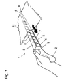
- FIG. 1 shows a dusting device 1 for dry dust wiping of flat objects.
- the dusting device 1 comprises a handle 2 on the two rods 3, 4 are spaced apart from each other.
- the rods 3, 4 are connected to each other at their free ends 5, 6.
- Between the rods 3, 4, a number of spacers 7 are arranged and connected via film hinges 8 hingedly connected to the rods 3, 4.
- the rods 3, 4 and the spacers 7 are made of a plastic, here polypropylene and are formed of the same material and in one piece. The production takes place in the injection molding process.
- the actuating device 9 comprises a push button which can be actuated by the thumb of an operator.
- the first rod 3 is extended at the same time and the second rod 4 is shortened, resulting in a predetermined curvature of the dusting device 1.
- a cleaning cloth 11 is stretched, which consists of a multi-layer nonwoven fabric and may include fringes for effective cleaning.
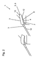
- FIG. 2 shows a dusting device according to FIG. 1 , wherein in this embodiment, a handle 10 is attached to the handle 2.
- the handle also has an actuating device which is connected to the actuating device 9 of the handle 2.
- the rods 3, 4 are formed flat and have a cleaning-active surface 12. For this purpose, cleaning-active fibers are adhered to the surfaces of the rods 3, 4.
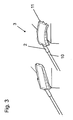
- FIG. 3 shows a dusting device 1 according to FIG. 2 , In this embodiment, a cleaning cloth 11 is clamped on the rods 3, 4.
Landscapes
- Cleaning Implements For Floors, Carpets, Furniture, Walls, And The Like (AREA)
- Acyclic And Carbocyclic Compounds In Medicinal Compositions (AREA)
- Peptides Or Proteins (AREA)
Abstract
Description
- Die Erfindung betrifft ein Staubwischgerät mit einem Griff an dem zwei Stäbe beabstandet voneinander befestigt sind.
- Derartige Staubwischgeräte sind aus der
DE 20 2004 004 793 U1 bekannt. Auf die Stäbe derartiger Staubwischgeräte werden Reinigungstücher aufgespannt, die eine Vielzahl von Faserabschnitten aufweisen. Zum Reinigen wird das Staubwischgerät über die zu reinigenden Flächen geführt und die Staubverunreinigen werden in den Faserabschnitten aufgefangen. Die Stäbe derartiger Staubwischgeräte sind starr ausgebildet, so dass gekrümmte Flächen schwer zu reinigen sind. Des Weiteren sind Staubwischgeräte bekannt, bei denen an dem Griff ein Stiel befestigbar ist, so dass auch höher gelegene Flächen erreichbar sind. Auch diese Staubwischgeräte eigenen sich jedoch nur zur Reinigung ebener Flächen, da der Abschnitt des Staubwischgerätes der die Reinigungsfasern aufnimmt, starr ausgebildet ist und sich daher nicht geschwungenen Flächen anpassen kann. Des Weiteren können Kantenbereiche hoch gelegener Flächen nur schwer erreicht werden. - Der Erfindung liegt die Aufgabe zugrunde, ein Staubwischgerät zu entwickeln mit dem auch unebene Flächen vollflächig gereinigt werden können.
- Diese Aufgabe wird mit den Merkmalen von Anspruch 1 gelöst. Auf vorteilhafte Ausgestaltungen nehmen die Unteransprüche Bezug.
- Zur Lösung der Aufgabe sind die Stäbe an ihren freien Enden miteinander verbunden und zwischen den Stäben sind eine Anzahl von Abstandshaltern angeordnet.
- Die beiden Stäbe sind erfindungsgemäß elastisch ausgebildet und die Abstandshalter sind zug- und/oder druckstabil ausgebildet, um Kräfte vom einen auf den jeweils anderen Stab übertragen zu können. Ein erster Stab wird beim Berühren unebener Flächen oder durch eine anderweitige Auslenkung elastisch verformt und die Auslenkung des ersten Stabes wird aufgrund der Verbindung der Stäbe durch die Abstandshalter auf einen zweiten Stab übertragen. Dabei wirken beide Stäbe als Druck- und elastischer Biegestab. Bei Krafteinwirkung auf den ersten Stab übt dieser eine Zugkraft auf das Ende des zweiten Stabes aus, die den ersten Stab spannt und bogenförmig durchbiegt. Der zweite Stab bewirkt eine Gegenkraft zu der Zugkraft, wobei der zweite Stab einer Druckbiegespannung unterliegt. Die Abstandshalter verhindern, dass sich der Mittelteil des zweiten Stabes weiter vom ersten Stab entfernt, als durch die Länge des Abstandshalters vorgegeben, so dass der Mittelteil des zweiten Stabes nicht nach außen auswandern kann. Dies bewirkt eine bogenförmige Verkrümmung der Stäbe und damit eine bessere Reinigungsleistung bei unebenen oder schwer erreichbaren oder hoch gelegenen Flächen.
- Die Abstandshalter können gelenkig an den Stäben angeordnet sein. Dadurch verbessert sich Kraftübertragung vom Innen- auf den Außenschenkel sowie die Beweglichkeit der Auswringvorrichtung.
- Die gelenkige Anbindung der Abstandshalter kann mittels Filmscharnieren erfolgen. Filmscharniere weisen eine einfache Gestalt auf und sind daher einfach zu fertigen. Des Weiteren weisen Filmscharniere nur einen Freiheitsgrad auf, so dass bei hoher Flexibilität gleichzeitig eine hohe Stabilität des Staubwischgerätes erreicht wird.
- Die Stäbe und die Abstandshalter können materialeinheitlich und einstückig ausgebildet sein. Derartige Staubwischgeräte sind einfach und kostengünstig herstellbar. Des Weiteren besteht das Staubwischgerät vorzugsweise aus Kunststoff-Spritzguss, welches einfach und kostengünstig eine Fertigung in hohen Stückzahlen erlaubt.
- An dem Griff kann eine Betätigungseinrichtung vorgesehen sein, mittels der zumindest einer der beiden Stäbe verkürzbar oder verlängerbar ist. Dazu kann die Betätigungseinrichtung einen Druckknopf enthalten, der mit einer Mechanik so verbunden ist, dass durch das Betätigen des Druckknopfes ein Stab verlängert oder verkürzt wird. Durch das Verlängern oder Verkürzen eines Stabes können die Stäbe vorbestimmt gekrümmt werden, um die Reinigungsarbeit zu erleichtern und unebene Flächen effektiver reinigen zu können.
- Die Betätigungseinrichtung kann derart ausgebildet sein, dass gleichzeitig ein Stab verlängerbar und der andere Stab verkürzbar ist. Durch gleichzeitiges verlängern und verkürzen wird der Krümmungseffekt der Stäbe verstärkt und es verbessert sich nochmals die Reinigungsleistung.
- An dem Griff kann ein Stiel befestigbar sein. Durch den Stiel verbessert die Erreichbarkeit höher gelegener Flächen. Der Stiel kann dabei so ausgestaltet sein, dass auch an dem Griffende des Stiels die Betätigungseinrichtung bedient werden kann.
- Auf die Stäbe kann ein Reinigungstuch aufspannbar sein. Das Reinigungstuch kann als Mehrweg- oder als Einwegtuch ausgebildet sein. Bevorzugt besteht das Reinigungstuch aus einem Vliesstoff, welcher kostengünstig verfügbar ist.
- Zumindest einer der Stäbe kann eine reinigungsaktive Oberfläche aufweisen. Dazu kann auf einer Seite eines Stabes oder auf beiden Stäben eine Faserschicht befestigt sein, von der nach der Reinigungsarbeit anhaftende Verschmutzungen einfach entfernt werden können.
- Die Stäbe können flächig ausgebildet sein. Dadurch verbessert sich die Reinigungsleistung des Staubwischgerätes
- Einige Ausführungsbeispiele des erfindungsgemäßen Staubwischgerätes werden nachfolgend anhand der Figuren näher erläutert. Diese zeigen, jeweils schematisch:
-
Fig. 1 ein erfindungsgemäßes Staubwischgerät; -
Fig. 2 ein Staubwischgerät mit Stiel und reinigungsaktiven Stäben; -
Fig. 3 ein Staubwischgerät mit Stiel und aufgespanntem Reinigungstuch. -
Figur 1 zeigt ein Staubwischgerät 1 zum trockenen Staubwischwischen von flächigen Gegenständen. Das Staubwischgerät 1 umfasst einen Griff 2 an dem zwei Stäbe 3, 4 beabstandet voneinander befestigt sind. Die Stäbe 3, 4 sind an ihren freien Enden 5, 6 miteinander verbunden. Zwischen den Stäben 3, 4 sind eine Anzahl von Abstandshaltern 7 angeordnet und über Filmscharniere 8 gelenkig mit den Stäben 3, 4 verbunden. Die Stäbe 3, 4 und die Abstandshalter 7 bestehen aus einem Kunststoff, hier Polypropylen und sind materialeinheitlich und einstückig ausgebildet. Die Herstellung erfolgt im Spritzgießprozess. An dem Griff 2 befindet sich eine Betätigungseinrichtung 9. In dieser Ausführung umfasst die Betätigungseinrichtung 9 einen Druckknopf der durch den Daumen eines Bedieners betätigbar ist. Durch Betätigen des Druckknopfes der Betätigungseinrichtung 9 wird gleichzeitig der erste Stab 3 verlängert und der zweite Stab 4 verkürzt, was zu einer vorbestimmten Krümmung des Staubwischgerätes 1 führt. Auf die Stäbe 3, 4 ist ein Reinigungstuch 11 aufgespannt, welches aus einem mehrlagigen Vliesstoff besteht und zur effektiveren Reinigung Fransen umfassen kann. -
Figur 2 zeigt ein Staubwischgerät gemäßFigur 1 , wobei in dieser Ausgestaltung an dem Griff 2 ein Stiel 10 befestigt ist. Der Stiel weist ebenfalls eine Betätigungseinrichtung auf, die mit der Betätigungseinrichtung 9 des Griffs 2 verbunden ist. Die Stäbe 3, 4 sind flächig ausgebildet und weisen eine reinigungsaktive Oberfläche 12 auf. Dazu werden reinigungsaktive Fasern auf die Oberflächen der Stäbe 3, 4 aufgeklebt. -
Figur 3 zeigt ein Staubwischgerät 1 gemäßFigur 2 , wobei in dieser Ausgestaltung ein Reinigungstuch 11 auf die Stäbe 3, 4 aufgespannt ist.
Claims (10)
- Staubwischgerät (1) mit einem Griff (2) an dem zwei Stäbe (3, 4) beabstandet voneinander befestigt sind, dadurch gekennzeichnet, dass die Stäbe (3, 4) an ihren freien Enden (5, 6) miteinander verbunden sind und dass zwischen den Stäben (3, 4) eine Anzahl von Abstandshaltern (7) angeordnet sind.
- Staubwischgerät nach Anspruch 1, dadurch gekennzeichnet, dass die Abstandshalter (7) gelenkig an den Stäben (3, 4) angeordnet sind.
- Staubwischgerät nach Anspruch 1 oder 2, dadurch gekennzeichnet, dass die gelenkige Anbindung der Abstandshalter (7) mittels Filmscharniere (8) erfolgt.
- Staubwischgerät nach einem der Ansprüche 1 bis 3, dadurch gekennzeichnet, dass die Stäbe (3, 4) und die Abstandshalter (7) materialeinheitlich und einstückig ausgebildet sind.
- Staubwischgerät nach einem der Ansprüche 1 bis 4, dadurch gekennzeichnet, dass an dem Griff (2) eine Betätigungseinrichtung (9) vorgesehen ist, mittels der zumindest einer der beiden Stäbe (3, 4) verkürzbar oder verlängerbar ist.
- Staubwischgerät nach Anspruch 5, dadurch gekennzeichnet, dass die Betätigungseinrichtung (9) derart ausgebildet ist, dass gleichzeitig ein Stab (3) verlängerbar und der andere Stab (4) verkürzbar ist.
- Staubwischgerät nach einem der Ansprüche 1 bis 6, dadurch gekennzeichnet, dass an dem Griff (2) ein Stiel (10) befestigbar ist.
- Staubwischgerät nach einem der Ansprüche 1 bis 7, dadurch gekennzeichnet, dass auf die Stäbe (3, 4) ein Reinigungstuch (11) aufspannbar ist.
- Staubwischgerät nach einem der Ansprüche 1 bis 8, dadurch gekennzeichnet, dass zumindest einer der Stäbe (3, 4) eine reinigungsaktive Oberfläche (12) aufweist.
- Staubwischgerät nach einem der Ansprüche 1 bis 10, dadurch gekennzeichnet, dass die Stäbe (3, 4) flächig ausgebildet sind.
Applications Claiming Priority (1)
| Application Number | Priority Date | Filing Date | Title |
|---|---|---|---|
| DE102007018214A DE102007018214B4 (de) | 2007-04-16 | 2007-04-16 | Staubwischgerät |
Publications (2)
| Publication Number | Publication Date |
|---|---|
| EP1982629A1 true EP1982629A1 (de) | 2008-10-22 |
| EP1982629B1 EP1982629B1 (de) | 2010-01-13 |
Family
ID=39619437
Family Applications (1)
| Application Number | Title | Priority Date | Filing Date |
|---|---|---|---|
| EP08007162A Active EP1982629B1 (de) | 2007-04-16 | 2008-04-11 | Staubwischgerät |
Country Status (7)
| Country | Link |
|---|---|
| US (1) | US8136196B2 (de) |
| EP (1) | EP1982629B1 (de) |
| CN (1) | CN101288577B (de) |
| AT (1) | ATE454844T1 (de) |
| CA (1) | CA2629118C (de) |
| DE (2) | DE102007018214B4 (de) |
| ES (1) | ES2338494T3 (de) |
Cited By (1)
| Publication number | Priority date | Publication date | Assignee | Title |
|---|---|---|---|---|
| EP4151136A1 (de) * | 2021-09-17 | 2023-03-22 | Carl Freudenberg KG | Multidirektionales entstaubungswerkzeug |
Families Citing this family (14)
| Publication number | Priority date | Publication date | Assignee | Title |
|---|---|---|---|---|
| USD610320S1 (en) * | 2006-06-30 | 2010-02-16 | Kao Corporation | Wiping cloth used for mop |
| USD589221S1 (en) * | 2006-06-30 | 2009-03-24 | Kao Corporation | Wiping cloth used for mop |
| SE535130C2 (sv) * | 2009-12-22 | 2012-04-24 | Electrolux Ab | Rengöringsanordning och rengöringssystem |
| GB2550923B (en) * | 2016-05-31 | 2020-03-18 | Darius Development Ltd | A cleaner attachment device |
| US11458515B2 (en) | 2017-01-26 | 2022-10-04 | Unger Marketing International, Llc | Cleaning devices for cleaning of difficult to reach locations |
| US11006738B2 (en) | 2017-01-26 | 2021-05-18 | Unger Marketing International, Llc | Cleaning devices having selectively flexible or rigid handles |
| USD851409S1 (en) | 2018-01-24 | 2019-06-18 | Unger Marketing International, Llc | Detail brush handle |
| USD851408S1 (en) | 2018-01-24 | 2019-06-18 | Unger Marketing International, Llc | Cartridge brush |
| USD851410S1 (en) | 2018-01-24 | 2019-06-18 | Unger Marketing International, Llc | Adjustable brush handle |
| USD852510S1 (en) | 2018-01-24 | 2019-07-02 | Unger Marketing International, Llc | Adjustable brush handle |
| USD882963S1 (en) | 2018-07-24 | 2020-05-05 | Unger Marketing International, Llc | Cartridge brush |
| AU2023388305A1 (en) * | 2022-12-07 | 2025-04-17 | Carl Freudenberg Kg | Cleaning article |
| USD1072405S1 (en) | 2023-01-30 | 2025-04-22 | Unger Marketing International, Llc | Squeegee tool having a fixed blade |
| USD1093793S1 (en) * | 2024-10-31 | 2025-09-16 | Lanhu Brand Management (Hangzhou) Co., Ltd | Dusting tool |
Citations (4)
| Publication number | Priority date | Publication date | Assignee | Title |
|---|---|---|---|---|
| US1713815A (en) | 1928-02-20 | 1929-05-21 | Joseph T Berthelote | Swab holder and swab therefor |
| DE8910609U1 (de) * | 1989-09-06 | 1989-12-07 | Kelo, Pal, 4504 Georgsmarienhütte | Staubwedel |
| US20020148061A1 (en) | 2000-07-10 | 2002-10-17 | Yoshinori Tanaka | Cleaning article |
| DE202004004793U1 (de) * | 2004-03-26 | 2004-05-27 | Oimo Industrial Company Ltd. | Reinigungsbesen |
Family Cites Families (4)
| Publication number | Priority date | Publication date | Assignee | Title |
|---|---|---|---|---|
| US6230356B1 (en) * | 1998-07-24 | 2001-05-15 | Park Hyo-Moon | Toothbrush |
| US6357073B1 (en) * | 2000-04-10 | 2002-03-19 | Choy Heung Yue | Toothbrush |
| TW200412890A (en) * | 2002-09-05 | 2004-08-01 | Novalabs L L C | Toilet cleaning apparatus and caddy |
| DE102005008199A1 (de) | 2005-02-22 | 2006-08-31 | Glaxosmithkline Consumer Healthcare Gmbh & Co. Kg | Zahnbürste mit aktivem Anformelement |
-
2007
- 2007-04-16 DE DE102007018214A patent/DE102007018214B4/de active Active
-
2008
- 2008-04-11 EP EP08007162A patent/EP1982629B1/de active Active
- 2008-04-11 AT AT08007162T patent/ATE454844T1/de active
- 2008-04-11 ES ES08007162T patent/ES2338494T3/es active Active
- 2008-04-11 DE DE502008000311T patent/DE502008000311D1/de active Active
- 2008-04-15 CA CA2629118A patent/CA2629118C/en active Active
- 2008-04-15 US US12/103,485 patent/US8136196B2/en active Active
- 2008-04-16 CN CN2008100910957A patent/CN101288577B/zh active Active
Patent Citations (4)
| Publication number | Priority date | Publication date | Assignee | Title |
|---|---|---|---|---|
| US1713815A (en) | 1928-02-20 | 1929-05-21 | Joseph T Berthelote | Swab holder and swab therefor |
| DE8910609U1 (de) * | 1989-09-06 | 1989-12-07 | Kelo, Pal, 4504 Georgsmarienhütte | Staubwedel |
| US20020148061A1 (en) | 2000-07-10 | 2002-10-17 | Yoshinori Tanaka | Cleaning article |
| DE202004004793U1 (de) * | 2004-03-26 | 2004-05-27 | Oimo Industrial Company Ltd. | Reinigungsbesen |
Cited By (2)
| Publication number | Priority date | Publication date | Assignee | Title |
|---|---|---|---|---|
| EP4151136A1 (de) * | 2021-09-17 | 2023-03-22 | Carl Freudenberg KG | Multidirektionales entstaubungswerkzeug |
| AU2022218574B2 (en) * | 2021-09-17 | 2023-11-02 | Carl Freudenberg Kg | Multidirectional dusting tool |
Also Published As
| Publication number | Publication date |
|---|---|
| DE102007018214A1 (de) | 2008-10-23 |
| US8136196B2 (en) | 2012-03-20 |
| ES2338494T3 (es) | 2010-05-07 |
| CN101288577A (zh) | 2008-10-22 |
| CN101288577B (zh) | 2010-12-15 |
| US20080250589A1 (en) | 2008-10-16 |
| CA2629118A1 (en) | 2008-10-16 |
| CA2629118C (en) | 2011-03-08 |
| DE502008000311D1 (de) | 2010-03-04 |
| EP1982629B1 (de) | 2010-01-13 |
| DE102007018214B4 (de) | 2009-06-25 |
| ATE454844T1 (de) | 2010-01-15 |
Similar Documents
| Publication | Publication Date | Title |
|---|---|---|
| EP1982629B1 (de) | Staubwischgerät | |
| EP2068692B1 (de) | Auswringvorrichtung | |
| DE4329848A1 (de) | Wischgerät | |
| DE102011078562A1 (de) | Beheizbares Haarformgerät | |
| DE102008030309B4 (de) | Reinigungsgerät | |
| DE102014001161A1 (de) | Haltevorrichtung für Langkörper, insbesondere für Kabel | |
| WO2018029355A1 (de) | Verbindungsvorrichtung und leitungsführungseinrichtung | |
| EP1897480B1 (de) | Wischbezug | |
| DE202018006815U1 (de) | Reinigungsgeräte für die Reinigung von schwer zugänglichen Stellen | |
| DE102017118379A1 (de) | Reinigungseinrichtung mit einer motorisch angetriebenen Schwingplatte | |
| DE102008022291A1 (de) | Reinigungsmaschine, insbesondere Kehrsaugmaschine | |
| EP3318168B1 (de) | Moppbezughalter | |
| DE1057194B (de) | Kontaktglied fuer Steckertafeln oder dergleichen | |
| EP1715784A1 (de) | Vorrichtung zum reinigen eines hohlgefässes | |
| EP3035835B1 (de) | Torsionswringer | |
| EP2949253B1 (de) | SAUGFUß FÜR EINE BODENREINIGUNGSMASCHINE | |
| EP3662806B1 (de) | Bodenreinigungsgerät und bodenreinigungssystem | |
| EP1342445A2 (de) | Wischgerät | |
| EP3367869B1 (de) | Reinigungstextil, dessen verwendung und flachwischer, der ein solches reinigungstextil umfasst | |
| DE102013222108B3 (de) | Tragerahmen für eine Handhabungsvorrichtung, sowieHandhabungsvorrichtung | |
| CH272533A (de) | Stiel für Reinigungsgeräte wie Wischer, Flaumer und dergleichen. | |
| DE102007002875A1 (de) | Einziehvorrichtung zum Einziehen einer Bedruckstoffbahn in eine Druckmaschine | |
| EP2477519B1 (de) | Reinigungsbürste | |
| DE202005003627U1 (de) | Haarbürste mit verstellbaren Borsten | |
| EP3741714A1 (de) | Abstreifvorrichtung für förderbänder |
Legal Events
| Date | Code | Title | Description |
|---|---|---|---|
| PUAI | Public reference made under article 153(3) epc to a published international application that has entered the european phase |
Free format text: ORIGINAL CODE: 0009012 |
|
| AK | Designated contracting states |
Kind code of ref document: A1 Designated state(s): AT BE BG CH CY CZ DE DK EE ES FI FR GB GR HR HU IE IS IT LI LT LU LV MC MT NL NO PL PT RO SE SI SK TR |
|
| AX | Request for extension of the european patent |
Extension state: AL BA MK RS |
|
| 17P | Request for examination filed |
Effective date: 20081028 |
|
| AKX | Designation fees paid |
Designated state(s): AT BE BG CH CY CZ DE DK EE ES FI FR GB GR HR HU IE IS IT LI LT LU LV MC MT NL NO PL PT RO SE SI SK TR |
|
| GRAP | Despatch of communication of intention to grant a patent |
Free format text: ORIGINAL CODE: EPIDOSNIGR1 |
|
| GRAS | Grant fee paid |
Free format text: ORIGINAL CODE: EPIDOSNIGR3 |
|
| GRAA | (expected) grant |
Free format text: ORIGINAL CODE: 0009210 |
|
| AK | Designated contracting states |
Kind code of ref document: B1 Designated state(s): AT BE BG CH CY CZ DE DK EE ES FI FR GB GR HR HU IE IS IT LI LT LU LV MC MT NL NO PL PT RO SE SI SK TR |
|
| REG | Reference to a national code |
Ref country code: GB Ref legal event code: FG4D Free format text: NOT ENGLISH |
|
| REG | Reference to a national code |
Ref country code: CH Ref legal event code: EP |
|
| REG | Reference to a national code |
Ref country code: IE Ref legal event code: FG4D |
|
| REF | Corresponds to: |
Ref document number: 502008000311 Country of ref document: DE Date of ref document: 20100304 Kind code of ref document: P |
|
| REG | Reference to a national code |
Ref country code: NL Ref legal event code: T3 |
|
| REG | Reference to a national code |
Ref country code: GR Ref legal event code: EP Ref document number: 20100400862 Country of ref document: GR |
|
| LTIE | Lt: invalidation of european patent or patent extension |
Effective date: 20100113 |
|
| PG25 | Lapsed in a contracting state [announced via postgrant information from national office to epo] |
Ref country code: NO Free format text: LAPSE BECAUSE OF FAILURE TO SUBMIT A TRANSLATION OF THE DESCRIPTION OR TO PAY THE FEE WITHIN THE PRESCRIBED TIME-LIMIT Effective date: 20100413 Ref country code: HR Free format text: LAPSE BECAUSE OF FAILURE TO SUBMIT A TRANSLATION OF THE DESCRIPTION OR TO PAY THE FEE WITHIN THE PRESCRIBED TIME-LIMIT Effective date: 20100113 Ref country code: LT Free format text: LAPSE BECAUSE OF FAILURE TO SUBMIT A TRANSLATION OF THE DESCRIPTION OR TO PAY THE FEE WITHIN THE PRESCRIBED TIME-LIMIT Effective date: 20100113 Ref country code: IS Free format text: LAPSE BECAUSE OF FAILURE TO SUBMIT A TRANSLATION OF THE DESCRIPTION OR TO PAY THE FEE WITHIN THE PRESCRIBED TIME-LIMIT Effective date: 20100513 |
|
| REG | Reference to a national code |
Ref country code: IE Ref legal event code: FD4D |
|
| PG25 | Lapsed in a contracting state [announced via postgrant information from national office to epo] |
Ref country code: FI Free format text: LAPSE BECAUSE OF FAILURE TO SUBMIT A TRANSLATION OF THE DESCRIPTION OR TO PAY THE FEE WITHIN THE PRESCRIBED TIME-LIMIT Effective date: 20100113 Ref country code: SI Free format text: LAPSE BECAUSE OF FAILURE TO SUBMIT A TRANSLATION OF THE DESCRIPTION OR TO PAY THE FEE WITHIN THE PRESCRIBED TIME-LIMIT Effective date: 20100113 Ref country code: PL Free format text: LAPSE BECAUSE OF FAILURE TO SUBMIT A TRANSLATION OF THE DESCRIPTION OR TO PAY THE FEE WITHIN THE PRESCRIBED TIME-LIMIT Effective date: 20100113 Ref country code: LV Free format text: LAPSE BECAUSE OF FAILURE TO SUBMIT A TRANSLATION OF THE DESCRIPTION OR TO PAY THE FEE WITHIN THE PRESCRIBED TIME-LIMIT Effective date: 20100113 |
|
| PG25 | Lapsed in a contracting state [announced via postgrant information from national office to epo] |
Ref country code: RO Free format text: LAPSE BECAUSE OF FAILURE TO SUBMIT A TRANSLATION OF THE DESCRIPTION OR TO PAY THE FEE WITHIN THE PRESCRIBED TIME-LIMIT Effective date: 20100113 Ref country code: IE Free format text: LAPSE BECAUSE OF FAILURE TO SUBMIT A TRANSLATION OF THE DESCRIPTION OR TO PAY THE FEE WITHIN THE PRESCRIBED TIME-LIMIT Effective date: 20100113 Ref country code: EE Free format text: LAPSE BECAUSE OF FAILURE TO SUBMIT A TRANSLATION OF THE DESCRIPTION OR TO PAY THE FEE WITHIN THE PRESCRIBED TIME-LIMIT Effective date: 20100113 Ref country code: CY Free format text: LAPSE BECAUSE OF FAILURE TO SUBMIT A TRANSLATION OF THE DESCRIPTION OR TO PAY THE FEE WITHIN THE PRESCRIBED TIME-LIMIT Effective date: 20100113 Ref country code: SE Free format text: LAPSE BECAUSE OF FAILURE TO SUBMIT A TRANSLATION OF THE DESCRIPTION OR TO PAY THE FEE WITHIN THE PRESCRIBED TIME-LIMIT Effective date: 20100113 |
|
| PLBE | No opposition filed within time limit |
Free format text: ORIGINAL CODE: 0009261 |
|
| STAA | Information on the status of an ep patent application or granted ep patent |
Free format text: STATUS: NO OPPOSITION FILED WITHIN TIME LIMIT |
|
| PG25 | Lapsed in a contracting state [announced via postgrant information from national office to epo] |
Ref country code: SK Free format text: LAPSE BECAUSE OF FAILURE TO SUBMIT A TRANSLATION OF THE DESCRIPTION OR TO PAY THE FEE WITHIN THE PRESCRIBED TIME-LIMIT Effective date: 20100113 Ref country code: BG Free format text: LAPSE BECAUSE OF FAILURE TO SUBMIT A TRANSLATION OF THE DESCRIPTION OR TO PAY THE FEE WITHIN THE PRESCRIBED TIME-LIMIT Effective date: 20100413 Ref country code: CZ Free format text: LAPSE BECAUSE OF FAILURE TO SUBMIT A TRANSLATION OF THE DESCRIPTION OR TO PAY THE FEE WITHIN THE PRESCRIBED TIME-LIMIT Effective date: 20100113 Ref country code: MC Free format text: LAPSE BECAUSE OF NON-PAYMENT OF DUE FEES Effective date: 20100430 |
|
| 26N | No opposition filed |
Effective date: 20101014 |
|
| PG25 | Lapsed in a contracting state [announced via postgrant information from national office to epo] |
Ref country code: DK Free format text: LAPSE BECAUSE OF FAILURE TO SUBMIT A TRANSLATION OF THE DESCRIPTION OR TO PAY THE FEE WITHIN THE PRESCRIBED TIME-LIMIT Effective date: 20100113 |
|
| PG25 | Lapsed in a contracting state [announced via postgrant information from national office to epo] |
Ref country code: MT Free format text: LAPSE BECAUSE OF FAILURE TO SUBMIT A TRANSLATION OF THE DESCRIPTION OR TO PAY THE FEE WITHIN THE PRESCRIBED TIME-LIMIT Effective date: 20100113 |
|
| PG25 | Lapsed in a contracting state [announced via postgrant information from national office to epo] |
Ref country code: PT Free format text: LAPSE BECAUSE OF FAILURE TO SUBMIT A TRANSLATION OF THE DESCRIPTION OR TO PAY THE FEE WITHIN THE PRESCRIBED TIME-LIMIT Effective date: 20100613 Ref country code: LU Free format text: LAPSE BECAUSE OF NON-PAYMENT OF DUE FEES Effective date: 20100411 Ref country code: HU Free format text: LAPSE BECAUSE OF FAILURE TO SUBMIT A TRANSLATION OF THE DESCRIPTION OR TO PAY THE FEE WITHIN THE PRESCRIBED TIME-LIMIT Effective date: 20100714 |
|
| PG25 | Lapsed in a contracting state [announced via postgrant information from national office to epo] |
Ref country code: TR Free format text: LAPSE BECAUSE OF FAILURE TO SUBMIT A TRANSLATION OF THE DESCRIPTION OR TO PAY THE FEE WITHIN THE PRESCRIBED TIME-LIMIT Effective date: 20100113 |
|
| REG | Reference to a national code |
Ref country code: CH Ref legal event code: PL |
|
| PG25 | Lapsed in a contracting state [announced via postgrant information from national office to epo] |
Ref country code: CH Free format text: LAPSE BECAUSE OF NON-PAYMENT OF DUE FEES Effective date: 20120430 Ref country code: LI Free format text: LAPSE BECAUSE OF NON-PAYMENT OF DUE FEES Effective date: 20120430 |
|
| REG | Reference to a national code |
Ref country code: AT Ref legal event code: MM01 Ref document number: 454844 Country of ref document: AT Kind code of ref document: T Effective date: 20130411 |
|
| PG25 | Lapsed in a contracting state [announced via postgrant information from national office to epo] |
Ref country code: AT Free format text: LAPSE BECAUSE OF NON-PAYMENT OF DUE FEES Effective date: 20130411 |
|
| PGFP | Annual fee paid to national office [announced via postgrant information from national office to epo] |
Ref country code: GR Payment date: 20140429 Year of fee payment: 7 |
|
| PG25 | Lapsed in a contracting state [announced via postgrant information from national office to epo] |
Ref country code: GR Free format text: LAPSE BECAUSE OF NON-PAYMENT OF DUE FEES Effective date: 20151106 |
|
| REG | Reference to a national code |
Ref country code: GR Ref legal event code: ML Ref document number: 20100400862 Country of ref document: GR Effective date: 20151106 |
|
| REG | Reference to a national code |
Ref country code: FR Ref legal event code: PLFP Year of fee payment: 9 |
|
| REG | Reference to a national code |
Ref country code: FR Ref legal event code: PLFP Year of fee payment: 10 |
|
| REG | Reference to a national code |
Ref country code: FR Ref legal event code: PLFP Year of fee payment: 11 |
|
| PGFP | Annual fee paid to national office [announced via postgrant information from national office to epo] |
Ref country code: NL Payment date: 20250424 Year of fee payment: 18 |
|
| PGFP | Annual fee paid to national office [announced via postgrant information from national office to epo] |
Ref country code: DE Payment date: 20250428 Year of fee payment: 18 |
|
| PGFP | Annual fee paid to national office [announced via postgrant information from national office to epo] |
Ref country code: GB Payment date: 20250422 Year of fee payment: 18 Ref country code: ES Payment date: 20250513 Year of fee payment: 18 |
|
| PGFP | Annual fee paid to national office [announced via postgrant information from national office to epo] |
Ref country code: BE Payment date: 20250424 Year of fee payment: 18 Ref country code: IT Payment date: 20250422 Year of fee payment: 18 |
|
| PGFP | Annual fee paid to national office [announced via postgrant information from national office to epo] |
Ref country code: FR Payment date: 20250424 Year of fee payment: 18 |