EP1981132A2 - Schirmhülse - Google Patents
Schirmhülse Download PDFInfo
- Publication number
- EP1981132A2 EP1981132A2 EP08103116A EP08103116A EP1981132A2 EP 1981132 A2 EP1981132 A2 EP 1981132A2 EP 08103116 A EP08103116 A EP 08103116A EP 08103116 A EP08103116 A EP 08103116A EP 1981132 A2 EP1981132 A2 EP 1981132A2
- Authority
- EP
- European Patent Office
- Prior art keywords
- sleeve
- line
- bending line
- umbrella
- cutout
- Prior art date
- Legal status (The legal status is an assumption and is not a legal conclusion. Google has not performed a legal analysis and makes no representation as to the accuracy of the status listed.)
- Granted
Links
Images


Classifications
-
- H—ELECTRICITY
- H01—ELECTRIC ELEMENTS
- H01R—ELECTRICALLY-CONDUCTIVE CONNECTIONS; STRUCTURAL ASSOCIATIONS OF A PLURALITY OF MUTUALLY-INSULATED ELECTRICAL CONNECTING ELEMENTS; COUPLING DEVICES; CURRENT COLLECTORS
- H01R43/00—Apparatus or processes specially adapted for manufacturing, assembling, maintaining, or repairing of line connectors or current collectors or for joining electric conductors
- H01R43/16—Apparatus or processes specially adapted for manufacturing, assembling, maintaining, or repairing of line connectors or current collectors or for joining electric conductors for manufacturing contact members, e.g. by punching and by bending
-
- H—ELECTRICITY
- H01—ELECTRIC ELEMENTS
- H01R—ELECTRICALLY-CONDUCTIVE CONNECTIONS; STRUCTURAL ASSOCIATIONS OF A PLURALITY OF MUTUALLY-INSULATED ELECTRICAL CONNECTING ELEMENTS; COUPLING DEVICES; CURRENT COLLECTORS
- H01R13/00—Details of coupling devices of the kinds covered by groups H01R12/70 or H01R24/00 - H01R33/00
- H01R13/648—Protective earth or shield arrangements on coupling devices, e.g. anti-static shielding
- H01R13/658—High frequency shielding arrangements, e.g. against EMI [Electro-Magnetic Interference] or EMP [Electro-Magnetic Pulse]
- H01R13/6581—Shield structure
-
- H—ELECTRICITY
- H01—ELECTRIC ELEMENTS
- H01R—ELECTRICALLY-CONDUCTIVE CONNECTIONS; STRUCTURAL ASSOCIATIONS OF A PLURALITY OF MUTUALLY-INSULATED ELECTRICAL CONNECTING ELEMENTS; COUPLING DEVICES; CURRENT COLLECTORS
- H01R24/00—Two-part coupling devices, or either of their cooperating parts, characterised by their overall structure
- H01R24/38—Two-part coupling devices, or either of their cooperating parts, characterised by their overall structure having concentrically or coaxially arranged contacts
- H01R24/40—Two-part coupling devices, or either of their cooperating parts, characterised by their overall structure having concentrically or coaxially arranged contacts specially adapted for high frequency
-
- H—ELECTRICITY
- H01—ELECTRIC ELEMENTS
- H01R—ELECTRICALLY-CONDUCTIVE CONNECTIONS; STRUCTURAL ASSOCIATIONS OF A PLURALITY OF MUTUALLY-INSULATED ELECTRICAL CONNECTING ELEMENTS; COUPLING DEVICES; CURRENT COLLECTORS
- H01R2103/00—Two poles
Definitions
- the invention relates to a shielding sleeve of a connector connected to an electrical line having at least one arranged on a contact carrier contact, wherein the shielding sleeve has a contact-side cylindrical sleeve portion and a line-side cylindrical sleeve portion.
- the connector may be formed as a plug having at least one contact pin. However, it can also be designed as a socket having at least one contact socket. Moreover, it is imperative that the electrical leads provided with connectors at their ends ensure that not only the cable but also the connector and in particular the junction between the lead and the connector are adequately shielded. This is done by the screen sleeve in question.
- the electrical line or the cable is externally enveloped at least in the region of the line-side sleeve portion with a braided shield.
- the connection between this sleeve portion and the electrical conductor is made by Deformation of this sleeve section.
- the shielding sleeve is therefore made of a suitable metal, such as brass.
- the previously known shielding sleeves are assembled from several individual parts. In addition, different items for the different angular positions of the sleeve sections are necessary. The previously known shielding sleeves are therefore relatively expensive.
- the invention has for its object to make a shielding sleeve of the type described in more detail so that it is inexpensive to produce and that within an angular range, the two sleeve sections of an aligned starting position of the two sleeve sections are continuously brought into a position to each other, in which the two sleeve sections are perpendicular to each other.
- the stated object is achieved by integrally forming the shielding sleeve, and in that the transition region between the two initially aligned end sections is provided with a cutout such that a defined bending line is formed, so that the two sleeve sections can be brought into angular positions relative to one another.
- the one-piece design of the shielding sleeve it is now not necessary that several items are joined together to form a completely closed shielding sleeve.
- the cutout for generating the bending line can be produced with suitable manufacturing methods without further deformation of the cylindrical sleeve sections.
- Another advantage is to be seen in the fact that the sleeve sections can be brought to each other in the desired angular positions, without structural changes must be made. These angular positions are in a preferred embodiment between 90 ° and 180 °.
- the two sleeve sections of the initially aligned initial position can be brought to each other steplessly in a 90 ° position.
- a constant blank can be used for different versions of the shielding sleeve now always a constant blank.
- the section is geometrically indefinable. However, so that a 90 ° position of the sleeve sections to each other can be achieved, the cut-out, relative to the aligned position of the sleeve sections, decreases in the direction of the bending line.
- the cutout is designed so that the two sleeve sections are connected to each other via a segment. It is provided that the edges bounding the cutout of the two sleeve sections extend angularly, wherein the transitions of the legs extend in an arc and the included angle is preferably an obtuse angle. Furthermore, the cutout is designed such that the two legs facing the bending line run parallel or approximately parallel to one another, whereby the transition region of these two legs facing the bending line likewise runs in an arc.
- the bending line is determined by the center of curvature.
- the cutout is designed so that at least in the 90 ° position of the two sleeve sections to each other in the aligned position the neckline limiting edges overlap. As a result, it is also achieved that a certain area of the contact carrier-side sleeve section engages under the conductor-side section, that is, this section lies inside. This also creates a contact surface.
- a connector 1 is shown, which is equipped as a plug with at least one contact pin or as a socket with at least one contact socket. These contacts are attached in a manner not shown to a contact carrier, which is connected to an electrical line 2. For secure connection of the connector 1 with a counterpart this is provided on the side facing away from the electrical line 2 with a threaded connector 3 and a union nut 4.
- the connector 1 is with a reference to the FIGS. 2 to 4 equipped in more detail shielding sleeve 5, which surrounds the electrical line 2 and is located within a handle.
- the FIG. 2 shows the shielding sleeve 5 in the starting position or as a blank.
- the shielding sleeve 5 is divided into two sleeve sections 6, 7.
- the middle or the transition region is provided with a cutout 8 which extends beyond the central longitudinal axis, so that a web is formed for connecting the two sleeve sections 6, 7.
- This bridge forms the bending line 9, according to the Figures 3 and 4 bring the two sleeve sections 6, 7 in an angular position.
- the shielding sleeve 5 is preferably made of brass with an outer coating of nickel. It is preferably produced by deep drawing.
- the edges of the sleeve sections 6, 7 delimiting the cutout 8 are angular, the transitional areas between the legs extending in a radius.
- the area associated with the bending line 9 likewise runs in an arc, wherein the center of curvature defines the bending line 9.
- the two regions assigned to the bending line 9 extend approximately parallel to one another.
- the length of the cutout on the side facing away from the bending line 9 is a multiple of the length of the bending line 9 facing region, in the exemplary embodiment about four times.
- FIG. 3 shows the shielding sleeve 5, wherein the two sleeve sections 6, 7 are at an obtuse angle to each other.
- the included angle of the central longitudinal axes is 135 °.
- the FIG. 3 shows that in this position, the radius associated region of the cutout 8 bounding edge of the contact carrier side sleeve portion 6 below the range of the radius associated region of the cutout 8 bounding edge of the line-side sleeve portion 7 engages below. As a result, a contact surface 10 is created.
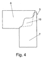
- This contact surface 10 increases when the two sleeve sections 6, 7 are perpendicular to each other, like the FIG. 4 shows.
- the included by the central longitudinal axes of the sleeve sections 6, 7 angle can be selected continuously.
- the shielding sleeve 5 in the in the FIG. 2 shown position used.
- the invention is not limited to the illustrated embodiment. It is essential that the shielding sleeve 5 is formed from two sleeve sections 6, 7, wherein the transition region is formed by the cutout 8, whereby the bending line 9 is determined.
Landscapes
- Engineering & Computer Science (AREA)
- Manufacturing & Machinery (AREA)
- Details Of Connecting Devices For Male And Female Coupling (AREA)
- Connector Housings Or Holding Contact Members (AREA)
Abstract
Description
- Die Erfindung bezieht sich auf eine Schirmhülse eines an eine elektrische Leitung angeschlossenen Steckverbinders, der mindestens einen an einen Kontaktträger angeordneten Kontakt aufweist, wobei die Schirmhülse einen kontaktseitigen zylindrischen Hülsenabschnitt und einen leitungsseitigen zylindrischen Hülsenabschnitt aufweist.
- Es ist gelegentlich erforderlich, elektrische Leitungen - z.B. des Hochfrequenzbereiches - abzuschirmen. Der Steckverbinder kann als Stecker ausgebildet sein, der wenigstens einen Kontaktstift aufweist. Er kann jedoch auch als Buchse ausgebildet sein, die wenigstens eine Kontaktbuchse aufweist. Darüber hinaus ist es unbedingt erforderlich, dass bei den elektrischen Leitungen, die an ihren Enden mit Steckverbindern versehen sind, dass nicht nur das Kabel, sondern auch der Steckverbinder und insbesondere der Übergang zwischen der Leitung und dem Steckverbinder hinreichend abgeschirmt ist. Dies erfolgt durch die in Rede stehende Schirmhülse.
- Die elektrische Leitung oder das Kabel ist außen zumindest im Bereich des leitungsseitigen Hülsenabschnittes mit einem Schirmgeflecht umhüllt. Die Verbindung zwischen diesem Hülsenabschnitt und dem elektrischen Leiter erfolgt durch Verformung dieses Hülsenabschnittes. Die Schirmhülse ist deshalb aus einem geeigneten Metall, beispielsweise aus Messing gefertigt.
- Die bislang bekannten Schirmhülsen werden aus mehreren Einzelteilen zusammengefügt. Außerdem sind unterschiedliche Einzelteile für die verschiedenen Winkelstellungen der Hülsenabschnitte notwendig. Die bislang bekannten Schirmhülsen sind demzufolge relativ kostenaufwendig.
- Der Erfindung liegt die Aufgabe zugrunde, eine Schirmhülse der eingangs näher beschriebenen Art so zu gestalten, dass sie kostengünstig herstellbar ist und dass innerhalb eines Winkelbereiches die beiden Hülsenabschnitte von einer fluchtenden Ausgangsstellung der beiden Hülsenabschnitte stufenlos bis in eine Stellung zueinander bringbar sind, in der die beiden Hülsenabschnitte senkrecht zueinander stehen.
- Die gestellte Aufgabe wird gelöst, indem die Schirmhülse einstückig ausgebildet ist, und dass der Übergangsbereich zwischen den beiden zunächst fluchtenden Endabschnitten derart mit einem Ausschnitt versehen ist, dass eine definierte Biegelinie gebildet ist, so dass die beiden Hülsenabschnitte zueinander in Winkelstellungen bringbar sind.
- Durch die einstückige Ausbildung der Schirmhülse ist es nunmehr nicht erforderlich, dass mehrere Einzelteile zu einer rundum geschlossenen Schirmhülse zusammengefügt werden. Der Ausschnitt zur Erzeugung der Biegelinie lässt sich mit geeigneten Fertigungsverfahren ohne weitere Verformung der zylindrischen Hülsenabschnitte herstellen. Ein weiterer Vorteil ist noch darin zu sehen, dass die Hülsenabschnitte in den jeweils gewünschten Winkelstellungen zueinander bringbar sind, ohne dass bauliche Veränderungen vorgenommen werden müssen. Diese Winkelstellungen liegen in bevorzugter Ausführung zwischen 90° und 180°.
- Dabei ist besonders vorteilhaft, dass die beiden Hülsenabschnitte von der zunächst fluchtenden Ausgangsstellung stufenlos bis in eine 90°-Stellung zueinander bringbar sind. Für verschiedene Ausführungen der Schirmhülse kann nunmehr ein stets gleichbleibender Rohling verwendet werden.
- Der Ausschnitt ist geometrisch nicht definierbar. Damit jedoch auch eine 90°-Stellung der Hülsenabschnitte zueinander erreicht werden kann, verkleinert sich der Ausschnitt, bezogen auf die fluchtende Stellung der Hülsenabschnitte, in Richtung zur Biegelinie. Der Ausschnitt ist so ausgeführt, dass über ein Segment die beiden Hülsenabschnitte miteinander verbunden sind. Dabei ist vorgesehen, dass die den Ausschnitt begrenzenden Ränder der beiden Hülsenabschnitte winkelförmig verlaufen, wobei die Übergänge der Schenkel in einem Bogen verlaufen und der eingeschlossene Winkel vorzugsweise ein stumpfer Winkel ist. Ferner ist der Ausschnitt so gestaltet, dass die beiden der Biegelinie zugewandten Schenkel parallel oder annähernd parallel zueinander verlaufen, wobei der der Biegelinie zugewandte Übergangsbereich dieser beiden Schenkel ebenfalls in einem Bogen verläuft. Dabei wird durch den Krümmungsmittelpunkt die Biegelinie bestimmt.
- Der Ausschnitt ist so ausgelegt, dass zumindest in der 90°-Stellung der beiden Hülsenabschnitte zueinander sich die in der fluchtenden Stellung den Ausschnitt begrenzenden Ränder überlappen. Dadurch wird auch noch erreicht, dass ein bestimmter Bereich des kontaktträgerseitigen Hülsenabschnittes den leiterseitigen Abschnitt untergreift, d.h., dieser Abschnitt liegt innen. Dadurch wird außerdem eine Kontaktfläche geschaffen.
- Anhand der beiliegenden Zeichnungen wird die Erfindung noch näher erläutert.
- Es zeigen:
- Figur 1
- einen mit der erfindungsgemäßen Schirmhülse ausgestatteten Steckverbinder in einer Ansicht
- Figur 2
- die Schirmhülse als Rohling bzw. in der Ausgangsstellung, bei der die Hülsenabschnitte fluchtend zueinander stehen
- Figur 3
- die Schirmhülse in einer Stellung, bei der die beiden Hülsenabschnitte unter einem stumpfen Winkel zueinander stehen und
- Figur 4
- die Schirmhülse in einer Ausführung, bei der die beiden Hülsenabschnitte im rechten Winkel zueinander stehen.
- In der
Figur 1 ist ein Steckverbinder 1 dargestellt, der als Stecker mit mindestens einem Kontaktstift oder als Steckdose mit mindestens einer Kontaktbuchse ausgerüstet ist. Diese Kontakte sind in nicht dargestellter Weise an einem Kontaktträger angesetzt, der mit einer elektrischen Leitung 2 verbunden ist. Zur sicheren Verbindung des Steckverbinders 1 mit einem Gegenstück ist dieser an der der elektrischen Leitung 2 abgewandten Seite mit einem Gewindestutzen 3 und einer Überwurfmutter 4 ausgestattet. Der Steckverbinder 1 ist mit einer anhand derFiguren 2 bis 4 noch näher erläuterten Schirmhülse 5 ausgestattet, die die elektrische Leitung 2 umgreift und innerhalb eines Griffstückes liegt. - Die
Figur 2 zeigt die Schirmhülse 5 in der Ausgangsstellung bzw. als Rohling. Die Schirmhülse 5 ist in zwei Hülsenabschnitte 6, 7 unterteilt. Der mittlere bzw. der Übergangsbereich ist mit einem Ausschnitt 8 versehen, der sich bis über die Mittellängsachse hinaus erstreckt, so dass zur Verbindung der beiden Hülsenabschnitte 6, 7 ein Steg gebildet wird. Dieser Steg bildet die Biegelinie 9, um gemäß denFiguren 3 und4 die beiden Hülsenabschnitte 6, 7 in eine Winkelstellung zu bringen. Die Schirmhülse 5 besteht in bevorzugter Ausführung aus Messing mit einer äußeren Beschichtung aus Nickel. Sie wird bevorzugt im Tiefziehverfahren hergestellt. - Wie die
Figur 2 zeigt, verkleinert sich der Ausschnitt 8 in Richtung zur Biegelinie 9. Die den Ausschnitt 8 begrenzenden Ränder der Hülsenabschnitte 6, 7 verlaufen winkelförmig, wobei die Übergangsbereiche zwischen den Schenkeln in einem Radius verlaufen. Ferner verläuft der der Biegelinie 9 zugeordnete Bereich ebenfalls in einem Bogen, wobei der Krümmungsmittelpunkt die Biegelinie 9 definiert. Die beiden der Biegelinie 9 zugeordneten Bereiche verlaufen darüber hinaus annähernd parallel zueinander. Die Länge des Ausschnittes an der der Biegelinie 9 abgewandten Seite beträgt ein Vielfaches der Länge des der Biegelinie 9 zugewandten Bereiches, im Ausführungsbeispiel etwa das Vierfache. - Die
Figur 3 zeigt die Schirmhülse 5, bei der die beiden Hülsenabschnitte 6, 7 unter einem stumpfen Winkel zueinander stehen. Im dargestellten Ausführungsbeispiel beträgt der von den Mittellängsachsen eingeschlossene Winkel 135°. DieFigur 3 zeigt, dass sich auch in dieser Stellung der dem Radius zugeordnete Bereich des den Ausschnitt 8 begrenzenden Randes des kontaktträgerseitigen Hülsenabschnittes 6 unter den Bereich des dem Radius zugeordneten Bereiches des den Ausschnitt 8 begrenzenden Randes des leitungsseitigen Hülsenabschnittes 7 untergreift. Dadurch wird eine Kontaktfläche 10 geschaffen. - Diese Kontaktfläche 10 vergrößert sich, wenn die beiden Hülsenabschnitte 6, 7 senkrecht zueinander stehen, wie die
Figur 4 zeigt. - Es sei noch erwähnt, dass in nicht dargestellter Weise der von den Mittellängsachsen der Hülsenabschnitte 6, 7 eingeschlossene Winkel stufenlos gewählt werden kann. Bei der dargestellten Ausführung kann die Schirmhülse 5 auch in der in der
Figur 2 dargestellten Stellung verwendet werden. - Die Erfindung ist nicht auf das dargestellte Ausführungsbeispiel beschränkt. Wesentlich ist, dass die Schirmhülse 5 aus zwei Hülsenabschnitten 6, 7 gebildet ist, wobei der Übergangsbereich durch den Ausschnitt 8 gebildet ist, wodurch die Biegelinie 9 bestimmt ist.
Claims (7)
- Schirmhülse (5) eines an eine elektrische Leitung (2) angeschlossenen Steckverbinders (1), der mindestens einen an einem Kontaktträger angeordneten Kontakt aufweist, wobei die Schirmhülse (5) einen kontaktseitigen zylindrischen Hülsenabschnitt (6) und einen leitungsseitigen zylindrischen Hülsenabschnitt (7) aufweist, dadurch gekennzeichnet, dass die Schirmhülse (5) einstückig ausgebildet ist, dass der Übergangsbereich zwischen den beiden zunächst fluchtenden Hülsenabschnitten (6, 7) derart mit einem Ausschnitt (8) versehen ist, dass eine definierte Biegelinie (9) gebildet ist, so dass die beiden Hülsenabschnitte (6, 7) zueinander in Winkelstellungen bringbar sind.
- Schirmhülse nach Anspruch 1, dadurch gekennzeichnet, dass die beiden Hülsenabschnitte (6, 7) von der fluchtenden Ausgangsstellung stufenlos bis in eine 90°-Stellung zueinander bringbar sind.
- Schirmhülse nach Anspruch 1, dadurch gekennzeichnet, dass der Ausschnitt (8), bezogen auf die fluchtende Stellung der beiden Hülsenabschnitte (6, 7), sich in Richtung zur Biegelinie (9) verkleinert.
- Schirmhülse nach Anspruch 3, dadurch gekennzeichnet, dass die den Ausschnitt (8) begrenzenden Ränder des kontaktträgerseitigen Hülsenabschnittes (6) und des leitungsseitigen Hülsenabschnittes (7) winkelförmig verlaufen, wobei vorzugsweise der eingeschlossene Winkel ein stumpfer Winkel ist und wobei die beiden Schenkel im Übergangsbereich in einem Radius verlaufen.
- Schirmhülse nach Anspruch 3 und 4, dadurch gekennzeichnet, dass die der Biegelinie (9) zugewandten Randabschnitte parallel oder annähernd parallel zueinander verlaufen, wobei der Übergangsbereich in einem Bogen verläuft.
- Schirmhülse nach Anspruch 5, dadurch gekennzeichnet, dass der Krümmungsmittelpunkt des bogenförmigen Übergangsbereiches die Biegelinie (9) definiert.
- Schirmhülse nach einem oder mehreren der vorstehenden Ansprüche, dadurch gekennzeichnet, dass die Länge des Ausschnittes (8) in dem der Biegelinie (8) abgewandten Bereich ein Vielfaches, vorzugsweise ein Vierfaches der Länge des der Biegelinie zugewandten Bereiches liegt.
Applications Claiming Priority (1)
| Application Number | Priority Date | Filing Date | Title |
|---|---|---|---|
| DE202007005264U DE202007005264U1 (de) | 2007-04-10 | 2007-04-10 | Schirmhülse |
Publications (3)
| Publication Number | Publication Date |
|---|---|
| EP1981132A2 true EP1981132A2 (de) | 2008-10-15 |
| EP1981132A3 EP1981132A3 (de) | 2012-02-22 |
| EP1981132B1 EP1981132B1 (de) | 2014-11-19 |
Family
ID=39636967
Family Applications (1)
| Application Number | Title | Priority Date | Filing Date |
|---|---|---|---|
| EP08103116.3A Not-in-force EP1981132B1 (de) | 2007-04-10 | 2008-03-28 | Schirmhülse |
Country Status (3)
| Country | Link |
|---|---|
| US (1) | US7648396B2 (de) |
| EP (1) | EP1981132B1 (de) |
| DE (1) | DE202007005264U1 (de) |
Cited By (2)
| Publication number | Priority date | Publication date | Assignee | Title |
|---|---|---|---|---|
| EP3206265A1 (de) * | 2016-02-09 | 2017-08-16 | Yamaichi Electronics Deutschland GmbH | Gewinkelter steckverbinder und verfahren zum assemblieren |
| US10355399B2 (en) | 2015-08-24 | 2019-07-16 | Erni Production Gmbh & Co. Kg | Cable connector having a shielding sleeve and method for producing the same |
Families Citing this family (7)
| Publication number | Priority date | Publication date | Assignee | Title |
|---|---|---|---|---|
| US7794279B1 (en) * | 2009-08-28 | 2010-09-14 | Cheng Uei Precision Industry Co., Ltd. | Plug connector |
| US9350087B2 (en) | 2010-03-01 | 2016-05-24 | Franz Binder Gmbh + Co. Elektrische Bauelemente Kg | Method for producing an electric interface and interface |
| CN111505356B (zh) * | 2020-04-27 | 2022-09-16 | 贵州电网有限责任公司 | 一种带钝角接头的二次试验线 |
| DE102021107183A1 (de) | 2021-03-23 | 2022-09-29 | Reichle & De-Massari Ag | Steckverbindervorrichtung |
| KR20240025941A (ko) * | 2022-08-19 | 2024-02-27 | 에이치알에스코리아 주식회사 | 전기 커넥터 |
| DE102023116463B4 (de) | 2023-06-22 | 2025-03-13 | Fep Fahrzeugelektrik Pirna Gmbh & Co. Kg | Geschirmter HV-Steckverbinder mit einstückiger Schirmhülse |
| DE102024130784A1 (de) * | 2024-10-22 | 2026-04-23 | Weidmüller Interface GmbH & Co. KG | Elektrisches Steckverbindungsbauteil, insbesondere Daten- und Leistungssteckverbindungsbauteil und Verfahren zur Herstellung des Steckverbindungsbauteils |
Family Cites Families (14)
| Publication number | Priority date | Publication date | Assignee | Title |
|---|---|---|---|---|
| US2553083A (en) * | 1948-05-01 | 1951-05-15 | Essex Wire Corp | Sleeve type elbow terminal |
| US3597723A (en) * | 1970-05-01 | 1971-08-03 | Microdot Inc | Spark plug terminal |
| US3740702A (en) * | 1971-05-21 | 1973-06-19 | F Moray | Electrical wire terminal |
| US3813645A (en) * | 1972-02-11 | 1974-05-28 | Essex International Inc | Spark plug terminal |
| US3793616A (en) * | 1972-02-23 | 1974-02-19 | Belden Corp | Terminal connector |
| CA1083684A (en) * | 1975-07-23 | 1980-08-12 | Essex Group, Inc. | Ignition cable terminals and method of manufacture |
| US4073565A (en) * | 1976-01-21 | 1978-02-14 | Raymond Eugene B | Spark plug terminal |
| US4268104A (en) * | 1980-04-01 | 1981-05-19 | Kidder Kent A | Electrical connector |
| FR2507827B1 (fr) * | 1981-06-11 | 1985-10-04 | Electricfil Ind Sarl | Embout coude de raccordement electrique |
| US5733146A (en) * | 1996-04-01 | 1998-03-31 | Block; Dale A. | Shield for modular electrical connector |
| US6478622B1 (en) * | 2001-11-27 | 2002-11-12 | Hon Hai Precision Ind. Co., Ltd. | Small form-factor pluggable transceiver cage |
| JP2006040552A (ja) * | 2004-07-22 | 2006-02-09 | Yazaki Corp | シールドコネクタ |
| US7195518B2 (en) * | 2005-05-02 | 2007-03-27 | Tyco Electronics Corporation | Electrical connector with enhanced jack interface |
| US7255602B1 (en) * | 2006-11-02 | 2007-08-14 | Hamilton Sundstrand Corporation | Shielding for electrical cable assemblies |
-
2007
- 2007-04-10 DE DE202007005264U patent/DE202007005264U1/de not_active Expired - Lifetime
-
2008
- 2008-03-28 EP EP08103116.3A patent/EP1981132B1/de not_active Not-in-force
- 2008-04-07 US US12/080,838 patent/US7648396B2/en active Active
Cited By (2)
| Publication number | Priority date | Publication date | Assignee | Title |
|---|---|---|---|---|
| US10355399B2 (en) | 2015-08-24 | 2019-07-16 | Erni Production Gmbh & Co. Kg | Cable connector having a shielding sleeve and method for producing the same |
| EP3206265A1 (de) * | 2016-02-09 | 2017-08-16 | Yamaichi Electronics Deutschland GmbH | Gewinkelter steckverbinder und verfahren zum assemblieren |
Also Published As
| Publication number | Publication date |
|---|---|
| EP1981132B1 (de) | 2014-11-19 |
| DE202007005264U1 (de) | 2008-08-14 |
| EP1981132A3 (de) | 2012-02-22 |
| US20080254682A1 (en) | 2008-10-16 |
| US7648396B2 (en) | 2010-01-19 |
Similar Documents
| Publication | Publication Date | Title |
|---|---|---|
| EP1981132B1 (de) | Schirmhülse | |
| EP2912728B1 (de) | Kontaktvorrichtung | |
| EP2187480B1 (de) | Steckbuchse für Leiterplatten | |
| EP3625857B1 (de) | Zug- und druckentlastungsmittel in einem steckverbindergehäuse | |
| DE202015003177U1 (de) | Steckverbindung und Satz von Steckverbindungen | |
| DE102004018430A1 (de) | Elektrische und mechanische Verbindungsanordnung | |
| DE102015216545A1 (de) | Gehäuseanordnung, elektrischer Verbinder umfassend eine Gehäuseanordnung und elektrische Verbindungsanordnung umfassend einen elektrischen Verbinder | |
| WO2018007129A1 (de) | Elektrischer hochleistungskontakt | |
| EP2586105B1 (de) | Steckverbinder | |
| DE102017126185B4 (de) | Elektrisches Kontaktelement | |
| EP3206265B1 (de) | Gewinkelter steckverbinder und verfahren zum assemblieren | |
| EP2071676A2 (de) | Steckeranordnung | |
| DE102010052627A1 (de) | Mantelleitungscrimpverbindung für Zug- und Druckentlastung einschließlich Schirmübertragung zur Metallhülse | |
| DE10347306A1 (de) | Schirmanbindung | |
| DE102015114040B3 (de) | Kabelsteckverbinder mit einer Schirmhülse und Verfahren zu seiner Herstellung | |
| DE19948037B4 (de) | Elektrisches Steckverbindungselement und -system | |
| DE102016006923B4 (de) | Koaxialsteckverbinder | |
| WO2003103098A1 (de) | Kontaktelement für eine elektrische steckverbindung | |
| EP3123566B1 (de) | Kontaktbuchse für eine steckdose oder kupplung | |
| DE202013010545U1 (de) | Elektrisches Kontaktelement | |
| DE2601429C3 (de) | Koaxialkabel-Anschlußklemme | |
| DE102006006484A1 (de) | Steckerteil und Buchsenteil für eine elektrische Steckverbindung und elektrische Steckverbindungs-Anordnung mit einem solchen Steckerteil und Buchsenteil | |
| DE10229700C1 (de) | Steckverbinder, insbesondere geschirmter Winkel-Rundsteckvebinder | |
| EP4254683B1 (de) | Rundsteckverbinder und verfahren zum herstellen eines rundsteckverbinders | |
| DE102008062597B3 (de) | Verbindungselement mit mindestens einem elektrischen Steckkontakt und Verfahen zur Herstellung desselben |
Legal Events
| Date | Code | Title | Description |
|---|---|---|---|
| PUAI | Public reference made under article 153(3) epc to a published international application that has entered the european phase |
Free format text: ORIGINAL CODE: 0009012 |
|
| AK | Designated contracting states |
Kind code of ref document: A2 Designated state(s): AT BE BG CH CY CZ DE DK EE ES FI FR GB GR HR HU IE IS IT LI LT LU LV MC MT NL NO PL PT RO SE SI SK TR |
|
| AX | Request for extension of the european patent |
Extension state: AL BA MK RS |
|
| PUAL | Search report despatched |
Free format text: ORIGINAL CODE: 0009013 |
|
| AK | Designated contracting states |
Kind code of ref document: A3 Designated state(s): AT BE BG CH CY CZ DE DK EE ES FI FR GB GR HR HU IE IS IT LI LT LU LV MC MT NL NO PL PT RO SE SI SK TR |
|
| AX | Request for extension of the european patent |
Extension state: AL BA MK RS |
|
| RIC1 | Information provided on ipc code assigned before grant |
Ipc: H01R 43/16 20060101AFI20120126BHEP |
|
| 17P | Request for examination filed |
Effective date: 20120618 |
|
| AKX | Designation fees paid |
Designated state(s): AT BE BG CH CY CZ DE DK EE ES FI FR GB GR HR HU IE IS IT LI LT LU LV MC MT NL NO PL PT RO SE SI SK TR |
|
| GRAP | Despatch of communication of intention to grant a patent |
Free format text: ORIGINAL CODE: EPIDOSNIGR1 |
|
| INTG | Intention to grant announced |
Effective date: 20140714 |
|
| GRAS | Grant fee paid |
Free format text: ORIGINAL CODE: EPIDOSNIGR3 |
|
| GRAA | (expected) grant |
Free format text: ORIGINAL CODE: 0009210 |
|
| AK | Designated contracting states |
Kind code of ref document: B1 Designated state(s): AT BE BG CH CY CZ DE DK EE ES FI FR GB GR HR HU IE IS IT LI LT LU LV MC MT NL NO PL PT RO SE SI SK TR |
|
| REG | Reference to a national code |
Ref country code: GB Ref legal event code: FG4D Free format text: NOT ENGLISH |
|
| REG | Reference to a national code |
Ref country code: CH Ref legal event code: EP |
|
| REG | Reference to a national code |
Ref country code: AT Ref legal event code: REF Ref document number: 697504 Country of ref document: AT Kind code of ref document: T Effective date: 20141215 |
|
| REG | Reference to a national code |
Ref country code: IE Ref legal event code: FG4D Free format text: LANGUAGE OF EP DOCUMENT: GERMAN |
|
| REG | Reference to a national code |
Ref country code: DE Ref legal event code: R096 Ref document number: 502008012409 Country of ref document: DE Effective date: 20141224 |
|
| REG | Reference to a national code |
Ref country code: NL Ref legal event code: VDEP Effective date: 20141119 |
|
| REG | Reference to a national code |
Ref country code: LT Ref legal event code: MG4D |
|
| PG25 | Lapsed in a contracting state [announced via postgrant information from national office to epo] |
Ref country code: NO Free format text: LAPSE BECAUSE OF FAILURE TO SUBMIT A TRANSLATION OF THE DESCRIPTION OR TO PAY THE FEE WITHIN THE PRESCRIBED TIME-LIMIT Effective date: 20150219 Ref country code: FI Free format text: LAPSE BECAUSE OF FAILURE TO SUBMIT A TRANSLATION OF THE DESCRIPTION OR TO PAY THE FEE WITHIN THE PRESCRIBED TIME-LIMIT Effective date: 20141119 Ref country code: PT Free format text: LAPSE BECAUSE OF FAILURE TO SUBMIT A TRANSLATION OF THE DESCRIPTION OR TO PAY THE FEE WITHIN THE PRESCRIBED TIME-LIMIT Effective date: 20150319 Ref country code: NL Free format text: LAPSE BECAUSE OF FAILURE TO SUBMIT A TRANSLATION OF THE DESCRIPTION OR TO PAY THE FEE WITHIN THE PRESCRIBED TIME-LIMIT Effective date: 20141119 Ref country code: IS Free format text: LAPSE BECAUSE OF FAILURE TO SUBMIT A TRANSLATION OF THE DESCRIPTION OR TO PAY THE FEE WITHIN THE PRESCRIBED TIME-LIMIT Effective date: 20150319 Ref country code: LT Free format text: LAPSE BECAUSE OF FAILURE TO SUBMIT A TRANSLATION OF THE DESCRIPTION OR TO PAY THE FEE WITHIN THE PRESCRIBED TIME-LIMIT Effective date: 20141119 Ref country code: ES Free format text: LAPSE BECAUSE OF FAILURE TO SUBMIT A TRANSLATION OF THE DESCRIPTION OR TO PAY THE FEE WITHIN THE PRESCRIBED TIME-LIMIT Effective date: 20141119 |
|
| PG25 | Lapsed in a contracting state [announced via postgrant information from national office to epo] |
Ref country code: CY Free format text: LAPSE BECAUSE OF FAILURE TO SUBMIT A TRANSLATION OF THE DESCRIPTION OR TO PAY THE FEE WITHIN THE PRESCRIBED TIME-LIMIT Effective date: 20141119 Ref country code: PL Free format text: LAPSE BECAUSE OF FAILURE TO SUBMIT A TRANSLATION OF THE DESCRIPTION OR TO PAY THE FEE WITHIN THE PRESCRIBED TIME-LIMIT Effective date: 20141119 Ref country code: LV Free format text: LAPSE BECAUSE OF FAILURE TO SUBMIT A TRANSLATION OF THE DESCRIPTION OR TO PAY THE FEE WITHIN THE PRESCRIBED TIME-LIMIT Effective date: 20141119 Ref country code: GR Free format text: LAPSE BECAUSE OF FAILURE TO SUBMIT A TRANSLATION OF THE DESCRIPTION OR TO PAY THE FEE WITHIN THE PRESCRIBED TIME-LIMIT Effective date: 20150220 Ref country code: HR Free format text: LAPSE BECAUSE OF FAILURE TO SUBMIT A TRANSLATION OF THE DESCRIPTION OR TO PAY THE FEE WITHIN THE PRESCRIBED TIME-LIMIT Effective date: 20141119 Ref country code: SE Free format text: LAPSE BECAUSE OF FAILURE TO SUBMIT A TRANSLATION OF THE DESCRIPTION OR TO PAY THE FEE WITHIN THE PRESCRIBED TIME-LIMIT Effective date: 20141119 |
|
| PG25 | Lapsed in a contracting state [announced via postgrant information from national office to epo] |
Ref country code: SK Free format text: LAPSE BECAUSE OF FAILURE TO SUBMIT A TRANSLATION OF THE DESCRIPTION OR TO PAY THE FEE WITHIN THE PRESCRIBED TIME-LIMIT Effective date: 20141119 Ref country code: DK Free format text: LAPSE BECAUSE OF FAILURE TO SUBMIT A TRANSLATION OF THE DESCRIPTION OR TO PAY THE FEE WITHIN THE PRESCRIBED TIME-LIMIT Effective date: 20141119 Ref country code: EE Free format text: LAPSE BECAUSE OF FAILURE TO SUBMIT A TRANSLATION OF THE DESCRIPTION OR TO PAY THE FEE WITHIN THE PRESCRIBED TIME-LIMIT Effective date: 20141119 Ref country code: CZ Free format text: LAPSE BECAUSE OF FAILURE TO SUBMIT A TRANSLATION OF THE DESCRIPTION OR TO PAY THE FEE WITHIN THE PRESCRIBED TIME-LIMIT Effective date: 20141119 Ref country code: RO Free format text: LAPSE BECAUSE OF FAILURE TO SUBMIT A TRANSLATION OF THE DESCRIPTION OR TO PAY THE FEE WITHIN THE PRESCRIBED TIME-LIMIT Effective date: 20141119 |
|
| REG | Reference to a national code |
Ref country code: DE Ref legal event code: R097 Ref document number: 502008012409 Country of ref document: DE |
|
| PLBE | No opposition filed within time limit |
Free format text: ORIGINAL CODE: 0009261 |
|
| STAA | Information on the status of an ep patent application or granted ep patent |
Free format text: STATUS: NO OPPOSITION FILED WITHIN TIME LIMIT |
|
| 26N | No opposition filed |
Effective date: 20150820 |
|
| PG25 | Lapsed in a contracting state [announced via postgrant information from national office to epo] |
Ref country code: MC Free format text: LAPSE BECAUSE OF FAILURE TO SUBMIT A TRANSLATION OF THE DESCRIPTION OR TO PAY THE FEE WITHIN THE PRESCRIBED TIME-LIMIT Effective date: 20141119 Ref country code: LU Free format text: LAPSE BECAUSE OF FAILURE TO SUBMIT A TRANSLATION OF THE DESCRIPTION OR TO PAY THE FEE WITHIN THE PRESCRIBED TIME-LIMIT Effective date: 20150328 |
|
| REG | Reference to a national code |
Ref country code: CH Ref legal event code: PL |
|
| GBPC | Gb: european patent ceased through non-payment of renewal fee |
Effective date: 20150328 |
|
| PG25 | Lapsed in a contracting state [announced via postgrant information from national office to epo] |
Ref country code: IT Free format text: LAPSE BECAUSE OF FAILURE TO SUBMIT A TRANSLATION OF THE DESCRIPTION OR TO PAY THE FEE WITHIN THE PRESCRIBED TIME-LIMIT Effective date: 20141119 |
|
| REG | Reference to a national code |
Ref country code: FR Ref legal event code: ST Effective date: 20151130 |
|
| REG | Reference to a national code |
Ref country code: IE Ref legal event code: MM4A |
|
| PG25 | Lapsed in a contracting state [announced via postgrant information from national office to epo] |
Ref country code: CH Free format text: LAPSE BECAUSE OF NON-PAYMENT OF DUE FEES Effective date: 20150331 Ref country code: GB Free format text: LAPSE BECAUSE OF NON-PAYMENT OF DUE FEES Effective date: 20150328 Ref country code: IE Free format text: LAPSE BECAUSE OF NON-PAYMENT OF DUE FEES Effective date: 20150328 Ref country code: LI Free format text: LAPSE BECAUSE OF NON-PAYMENT OF DUE FEES Effective date: 20150331 |
|
| PG25 | Lapsed in a contracting state [announced via postgrant information from national office to epo] |
Ref country code: SI Free format text: LAPSE BECAUSE OF FAILURE TO SUBMIT A TRANSLATION OF THE DESCRIPTION OR TO PAY THE FEE WITHIN THE PRESCRIBED TIME-LIMIT Effective date: 20141119 Ref country code: FR Free format text: LAPSE BECAUSE OF NON-PAYMENT OF DUE FEES Effective date: 20150331 |
|
| REG | Reference to a national code |
Ref country code: AT Ref legal event code: MM01 Ref document number: 697504 Country of ref document: AT Kind code of ref document: T Effective date: 20150328 |
|
| PG25 | Lapsed in a contracting state [announced via postgrant information from national office to epo] |
Ref country code: AT Free format text: LAPSE BECAUSE OF NON-PAYMENT OF DUE FEES Effective date: 20150328 |
|
| PG25 | Lapsed in a contracting state [announced via postgrant information from national office to epo] |
Ref country code: MT Free format text: LAPSE BECAUSE OF FAILURE TO SUBMIT A TRANSLATION OF THE DESCRIPTION OR TO PAY THE FEE WITHIN THE PRESCRIBED TIME-LIMIT Effective date: 20141119 |
|
| PG25 | Lapsed in a contracting state [announced via postgrant information from national office to epo] |
Ref country code: HU Free format text: LAPSE BECAUSE OF FAILURE TO SUBMIT A TRANSLATION OF THE DESCRIPTION OR TO PAY THE FEE WITHIN THE PRESCRIBED TIME-LIMIT; INVALID AB INITIO Effective date: 20080328 Ref country code: BG Free format text: LAPSE BECAUSE OF FAILURE TO SUBMIT A TRANSLATION OF THE DESCRIPTION OR TO PAY THE FEE WITHIN THE PRESCRIBED TIME-LIMIT Effective date: 20141119 |
|
| PG25 | Lapsed in a contracting state [announced via postgrant information from national office to epo] |
Ref country code: BE Free format text: LAPSE BECAUSE OF NON-PAYMENT OF DUE FEES Effective date: 20150331 |
|
| PG25 | Lapsed in a contracting state [announced via postgrant information from national office to epo] |
Ref country code: TR Free format text: LAPSE BECAUSE OF FAILURE TO SUBMIT A TRANSLATION OF THE DESCRIPTION OR TO PAY THE FEE WITHIN THE PRESCRIBED TIME-LIMIT Effective date: 20141119 |
|
| PGFP | Annual fee paid to national office [announced via postgrant information from national office to epo] |
Ref country code: DE Payment date: 20180322 Year of fee payment: 11 |
|
| REG | Reference to a national code |
Ref country code: DE Ref legal event code: R119 Ref document number: 502008012409 Country of ref document: DE |
|
| PG25 | Lapsed in a contracting state [announced via postgrant information from national office to epo] |
Ref country code: DE Free format text: LAPSE BECAUSE OF NON-PAYMENT OF DUE FEES Effective date: 20191001 |