EP1981015A2 - Appareil d'affichage et son procédé de réglage de la luminosité - Google Patents
Appareil d'affichage et son procédé de réglage de la luminosité Download PDFInfo
- Publication number
- EP1981015A2 EP1981015A2 EP08150901A EP08150901A EP1981015A2 EP 1981015 A2 EP1981015 A2 EP 1981015A2 EP 08150901 A EP08150901 A EP 08150901A EP 08150901 A EP08150901 A EP 08150901A EP 1981015 A2 EP1981015 A2 EP 1981015A2
- Authority
- EP
- European Patent Office
- Prior art keywords
- denotes
- pixels
- brightness
- graylevel
- thr
- Prior art date
- Legal status (The legal status is an assumption and is not a legal conclusion. Google has not performed a legal analysis and makes no representation as to the accuracy of the status listed.)
- Withdrawn
Links
Images


Classifications
-
- G—PHYSICS
- G09—EDUCATION; CRYPTOGRAPHY; DISPLAY; ADVERTISING; SEALS
- G09G—ARRANGEMENTS OR CIRCUITS FOR CONTROL OF INDICATING DEVICES USING STATIC MEANS TO PRESENT VARIABLE INFORMATION
- G09G3/00—Control arrangements or circuits, of interest only in connection with visual indicators other than cathode-ray tubes
- G09G3/20—Control arrangements or circuits, of interest only in connection with visual indicators other than cathode-ray tubes for presentation of an assembly of a number of characters, e.g. a page, by composing the assembly by combination of individual elements arranged in a matrix no fixed position being assigned to or needed to be assigned to the individual characters or partial characters
- G09G3/2007—Display of intermediate tones
- G09G3/2044—Display of intermediate tones using dithering
-
- G—PHYSICS
- G09—EDUCATION; CRYPTOGRAPHY; DISPLAY; ADVERTISING; SEALS
- G09G—ARRANGEMENTS OR CIRCUITS FOR CONTROL OF INDICATING DEVICES USING STATIC MEANS TO PRESENT VARIABLE INFORMATION
- G09G3/00—Control arrangements or circuits, of interest only in connection with visual indicators other than cathode-ray tubes
- G09G3/20—Control arrangements or circuits, of interest only in connection with visual indicators other than cathode-ray tubes for presentation of an assembly of a number of characters, e.g. a page, by composing the assembly by combination of individual elements arranged in a matrix no fixed position being assigned to or needed to be assigned to the individual characters or partial characters
- G09G3/34—Control arrangements or circuits, of interest only in connection with visual indicators other than cathode-ray tubes for presentation of an assembly of a number of characters, e.g. a page, by composing the assembly by combination of individual elements arranged in a matrix no fixed position being assigned to or needed to be assigned to the individual characters or partial characters by control of light from an independent source
- G09G3/36—Control arrangements or circuits, of interest only in connection with visual indicators other than cathode-ray tubes for presentation of an assembly of a number of characters, e.g. a page, by composing the assembly by combination of individual elements arranged in a matrix no fixed position being assigned to or needed to be assigned to the individual characters or partial characters by control of light from an independent source using liquid crystals
-
- G—PHYSICS
- G02—OPTICS
- G02F—OPTICAL DEVICES OR ARRANGEMENTS FOR THE CONTROL OF LIGHT BY MODIFICATION OF THE OPTICAL PROPERTIES OF THE MEDIA OF THE ELEMENTS INVOLVED THEREIN; NON-LINEAR OPTICS; FREQUENCY-CHANGING OF LIGHT; OPTICAL LOGIC ELEMENTS; OPTICAL ANALOGUE/DIGITAL CONVERTERS
- G02F1/00—Devices or arrangements for the control of the intensity, colour, phase, polarisation or direction of light arriving from an independent light source, e.g. switching, gating or modulating; Non-linear optics
- G02F1/01—Devices or arrangements for the control of the intensity, colour, phase, polarisation or direction of light arriving from an independent light source, e.g. switching, gating or modulating; Non-linear optics for the control of the intensity, phase, polarisation or colour
- G02F1/13—Devices or arrangements for the control of the intensity, colour, phase, polarisation or direction of light arriving from an independent light source, e.g. switching, gating or modulating; Non-linear optics for the control of the intensity, phase, polarisation or colour based on liquid crystals, e.g. single liquid crystal display cells
- G02F1/133—Constructional arrangements; Operation of liquid crystal cells; Circuit arrangements
-
- G—PHYSICS
- G09—EDUCATION; CRYPTOGRAPHY; DISPLAY; ADVERTISING; SEALS
- G09G—ARRANGEMENTS OR CIRCUITS FOR CONTROL OF INDICATING DEVICES USING STATIC MEANS TO PRESENT VARIABLE INFORMATION
- G09G3/00—Control arrangements or circuits, of interest only in connection with visual indicators other than cathode-ray tubes
- G09G3/20—Control arrangements or circuits, of interest only in connection with visual indicators other than cathode-ray tubes for presentation of an assembly of a number of characters, e.g. a page, by composing the assembly by combination of individual elements arranged in a matrix no fixed position being assigned to or needed to be assigned to the individual characters or partial characters
- G09G3/34—Control arrangements or circuits, of interest only in connection with visual indicators other than cathode-ray tubes for presentation of an assembly of a number of characters, e.g. a page, by composing the assembly by combination of individual elements arranged in a matrix no fixed position being assigned to or needed to be assigned to the individual characters or partial characters by control of light from an independent source
- G09G3/3406—Control of illumination source
- G09G3/342—Control of illumination source using several illumination sources separately controlled corresponding to different display panel areas, e.g. along one dimension such as lines
- G09G3/3426—Control of illumination source using several illumination sources separately controlled corresponding to different display panel areas, e.g. along one dimension such as lines the different display panel areas being distributed in two dimensions, e.g. matrix
-
- G—PHYSICS
- G09—EDUCATION; CRYPTOGRAPHY; DISPLAY; ADVERTISING; SEALS
- G09G—ARRANGEMENTS OR CIRCUITS FOR CONTROL OF INDICATING DEVICES USING STATIC MEANS TO PRESENT VARIABLE INFORMATION
- G09G2320/00—Control of display operating conditions
- G09G2320/02—Improving the quality of display appearance
- G09G2320/0233—Improving the luminance or brightness uniformity across the screen
-
- G—PHYSICS
- G09—EDUCATION; CRYPTOGRAPHY; DISPLAY; ADVERTISING; SEALS
- G09G—ARRANGEMENTS OR CIRCUITS FOR CONTROL OF INDICATING DEVICES USING STATIC MEANS TO PRESENT VARIABLE INFORMATION
- G09G2320/00—Control of display operating conditions
- G09G2320/02—Improving the quality of display appearance
- G09G2320/0238—Improving the black level
-
- G—PHYSICS
- G09—EDUCATION; CRYPTOGRAPHY; DISPLAY; ADVERTISING; SEALS
- G09G—ARRANGEMENTS OR CIRCUITS FOR CONTROL OF INDICATING DEVICES USING STATIC MEANS TO PRESENT VARIABLE INFORMATION
- G09G2320/00—Control of display operating conditions
- G09G2320/02—Improving the quality of display appearance
- G09G2320/0247—Flicker reduction other than flicker reduction circuits used for single beam cathode-ray tubes
-
- G—PHYSICS
- G09—EDUCATION; CRYPTOGRAPHY; DISPLAY; ADVERTISING; SEALS
- G09G—ARRANGEMENTS OR CIRCUITS FOR CONTROL OF INDICATING DEVICES USING STATIC MEANS TO PRESENT VARIABLE INFORMATION
- G09G2320/00—Control of display operating conditions
- G09G2320/02—Improving the quality of display appearance
- G09G2320/0261—Improving the quality of display appearance in the context of movement of objects on the screen or movement of the observer relative to the screen
-
- G—PHYSICS
- G09—EDUCATION; CRYPTOGRAPHY; DISPLAY; ADVERTISING; SEALS
- G09G—ARRANGEMENTS OR CIRCUITS FOR CONTROL OF INDICATING DEVICES USING STATIC MEANS TO PRESENT VARIABLE INFORMATION
- G09G2320/00—Control of display operating conditions
- G09G2320/06—Adjustment of display parameters
- G09G2320/066—Adjustment of display parameters for control of contrast
-
- G—PHYSICS
- G09—EDUCATION; CRYPTOGRAPHY; DISPLAY; ADVERTISING; SEALS
- G09G—ARRANGEMENTS OR CIRCUITS FOR CONTROL OF INDICATING DEVICES USING STATIC MEANS TO PRESENT VARIABLE INFORMATION
- G09G2320/00—Control of display operating conditions
- G09G2320/06—Adjustment of display parameters
- G09G2320/0673—Adjustment of display parameters for control of gamma adjustment, e.g. selecting another gamma curve
-
- G—PHYSICS
- G09—EDUCATION; CRYPTOGRAPHY; DISPLAY; ADVERTISING; SEALS
- G09G—ARRANGEMENTS OR CIRCUITS FOR CONTROL OF INDICATING DEVICES USING STATIC MEANS TO PRESENT VARIABLE INFORMATION
- G09G2360/00—Aspects of the architecture of display systems
- G09G2360/16—Calculation or use of calculated indices related to luminance levels in display data
Definitions
- Apparatuses and methods consistent with the present invention relate to a display apparatus and a method for adjusting brightness thereof, and, more particularly, to a display apparatus which is capable of adjusting brightness of a screen locally, according to an incoming video signal, and a method for adjusting brightness thereof.
- Displays such as Liquid Crystal Displays (LCD) in TVs, laptops, or desktops represent images thereon. Because these types of displays do not generate lights by themselves, they require a separate light source to emit a ray of light.
- An LCD generally has an LCD panel and a light emitting unit with a backlight at the back of the LCD panel, and displays an image, while appropriately adjusting the LCD panel's transmissivity for the light radiating from the light emitting unit.
- Related art LCD generally use a uniform backlight for the light emitting unit, which supplies light over the entire LCD panel in a uniform manner.
- the uniform backlight is used, all the images, including dark and bright images, are represented by the light of the same level of brightness. Images including fireworks or explosions have some parts that need be represented by higher brightness, but due to the absence of counterbalance measures, it is difficult to represent lively images.
- the light generated at the uniform backlight falls onto the LCD panel, causing interference.
- a LCD is unable to display zero-pixel image as a true black image, and also has degradation of contrast ratio.
- Power consumption also increases, because uniform backlight emits the same brightness light even for a dark image which can be represented by a dimmer light.
- Exemplary embodiments of the present invention address the above disadvantages and other disadvantages not described above. Also, the present invention is not required to overcome the disadvantages described above, and an exemplary embodiment of the present invention may not overcome any of the problems described above.
- the present invention provides a display apparatus capable of adjusting brightness of light emitting unit in local areas of a screen, according to an incoming video signal, and a method for adjusting brightness thereof.
- the present invention also provides a display apparatus capable of pixel compensation in local areas, to prevent loss of video signal due to a light emitting unit having locally adjusted brightness, and a method for adjusting brightness thereof.
- the present invention also provides a display apparatus capable of adjusting brightness and compensating pixels with respect to an entire screen according to an incoming video signal, and preventing unnecessary power consumption.
- a display apparatus which may include a panel unit which displays a video signal, a light emitting unit which provides the panel unit with a ray of light and causes the video signal to be visualized, a light emission control unit which controls the light emitting unit so that the ray of light is provided to each of local areas of the panel unit, and a panel control unit which compensates pixels of the video signal in each of local areas, to remove an artifact which is generated due to the ray of light provided to the local areas of the panel unit.
- the panel control unit compensates the pixels of the local areas, using representative values which are computed by the light emission control unit to control the light emitting unit.
- the light emission control unit computes representative values according to the size of RGB pixels of the respective local areas of the incoming video signal, so that the light emitting unit is controlled to provide the panel unit with the ray of light according to the representative values.
- f c (i, j) denotes a compensation coefficient of the (i, j)th pixel
- Thr denotes a parameter for controlling a compensation gain
- f b (i, j) denotes an interpolated brightness of the (i, j)th pixel
- LUT BLU (f b (i, j) denotes an interpolated f b (i, j) based on the lookup table
- Y(i, j) max(R(i, j), G(i, j), B(i, j))
- LUT GRAY (Y(i, j) denotes an interpolated value of Y(i, j) based on the lookup table.
- f E (m, n) denotes estimate brightness of the respective local areas of the (m ⁇ n) screen
- BLK_NUM denotes the total number of local areas
- L LD (k) denotes a representative value of a local area (k)
- W k (m, n) denotes optical profile data of (m, n)th local area (k).
- L init (k) denotes an initial representative value of a local area (k)
- L_Thr denotes a predetermined coefficient for the brightness compensation of the local area (k)
- BLK_NUM denotes a total number of local areas
- N h denotes the number of graylevels
- N i denotes the number of pixels belonging to the (i)th graylevel of the graylevel histogram
- M denotes an average pixel of the (i)th graylevel of the graylevel histogram of the local area (k).
- the light emission control unit performs spatial and temporal filtering of the initial representative value, and outputs a representative value for controlling the light emitting unit.
- the panel control unit compensates brightness of the entire screen in consideration of the adjustment of the representative values by the pixels.
- IIR Infinite Impulse Response
- the panel control unit removes a contour artifact by dithering the R'G'B' pixels.
- a method for adjusting brightness of a display apparatus comprising a panel unit which displays a video signal, and a light emitting unit which provides the panel unit with a ray of light and causes the video signal to be visualized, which may include controlling the light emitting unit so that the ray of light is provided to each of local areas of the panel unit, and compensating pixels of the video signal in each of local areas, to remove an artifact which is generated due to the ray of light provided to local areas of the panel unit.
- the compensating may include compensating the pixels of the local areas, using representative values which are computed by the light emission control unit to control the light emitting unit.
- the controlling the light emitting unit may include computing representative values according to the size of RGB pixels of the respective local areas of the incoming video signal, so that the light emitting unit is controlled to provide the panel unit with the ray of light according to the representative values.
- f c (i, j) denotes a compensation coefficient of the (i, j)th pixel
- Thr denotes a parameter for controlling a compensation gain
- f b (i, j) denotes an interpolated brightness of the (i, j)th pixel
- LUT BLU (f b (i, j) denotes an interpolated f b (i, j) based on the lookup table
- Y(i, j) max(R(i, j), G(i, j), B(i, j))
- LUT GRAY (Y(i, j) denotes an interpolated value of Y(i, j) based on the lookup table.
- the controlling the light emitting unit may include performing spatial and temporal filtering of the initial representative value, and outputs a representative value for controlling the light emitting unit.
- Compensating brightness of the entire screen in consideration of the adjustment of the representative values by the pixels may be further provided.
- IIR Infinite Impulse Response
- the compensating the pixels comprises removing a contour artifact by dithering the R'G'B' pixels.
- the light emitting unit comprises at least one of a plurality of light-emitting diodes, a plurality of cold cathode fluorescent lamps, a plurality of field-effect diodes, and a plurality of surface-conduction electron-emitter displays.
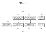
- FIG. 1 is a block diagram of a display apparatus according to an exemplary embodiment of the present invention.
- a display apparatus includes a video signal processing unit 100, a light emission control unit 200, a panel control unit 300, a light emitting unit 400, and a panel unit 500.
- the light emitting unit 400 includes a plurality of illuminating elements which generate light, and is divided into a plurality of local areas.
- the light emitting unit 400 may be divided into 8 ⁇ 8 (that is, 64) local areas.
- Each of the local areas include a one or more illuminating elements which are controlled to have the same brightness,
- the illuminating elements may include a light-emitting diode (LED), cold cathode fluorescent lamp (CCFL), field-effect diode (FED) or surface-conduction electron-emitter display (SED).
- the panel unit 500 adjusts transmissivity of light from the light emitting unit 400, such that a video signal is visualized and displayed on a screen.
- the panel unit 500 includes two electrode-generated boards facing each other, and liquid crystal material injected between these two boards. As the voltage is applied to the two electrodes, electric field is generated, causing liquid crystal molecules between the two boards to move and accordingly adjust light transmissivity.
- the video signal processing unit 100 processes an incoming video signal to suit for the resolution of the panel unit 500, and outputs as a RGB video signal.
- the light emission control unit 200 controls the light emitting unit 400 according to a RGB video signal output from the video signal processing unit 100, and accordingly adjusts the brightness of the plurality of illuminating elements of the light emitting unit 400.
- the light emission control unit 200 includes a local brightness adjusting unit 210 and a general brightness adjusting unit 230.
- the local brightness adjusting unit 210 controls the light emitting unit 400 to adjust the local areas of the screen according to luminance value which is computed using a RGB video signal.
- a representative value is computed using a RGB pixel of each of the local areas, and used in the brightness adjustment of the illuminating elements of the local areas.
- the general brightness adjusting unit 230 adjusts the representative values of the local areas according to the same ratio, so that the overall brightness of the screen can be adjusted according to the brightness of the image being displayed on the screen. That is, to represent a relatively dark image, the general brightness adjusting unit 230 controls the light emitting unit 400 so that the brightness of the entire screen is decreased at the same ratio.
- the brightness of the entire screen may be adjusted with reference to the R'G'B pixels being output from a local pixel compensating unit 310 which will be explained below.
- the panel control unit 300 compensates the pixels to be displayed on the panel unit 500, using the RGB video signal being output from the video signal processing unit 100, so that the contrast ratio of the screen is enhanced.
- the panel control unit 300 includes a local pixel compensating unit 310, and a general pixel compensating unit 330.
- the local pixel compensating unit 310 compensates RGB pixels in respective local areas, to offset the loss of video signal due to the local brightness adjustment of the light emitting unit 400.
- the local pixel compensating unit 310 compensates the RGB pixels to remove artefacts which are generated due to the brightness adjustment of the local areas by the local brightness adjusting unit 210, and outputs the artifact-removed pixels.
- the local pixel compensating unit 310 estimates the brightness of the respective local areas, after an optical profile for the screen is applied, using the representative values which are computed at the local brightness adjusting unit 210.
- the local pixel compensating unit 310 then compensates the estimated brightness to remove blocking artefacts.
- the local pixel compensating unit 310 then computes compensation coefficients of the respective local areas using the compensated brightness, and outputs R'G'B' pixels, which are the compensated RGB pixels, using the computed compensation coefficients.
- the general pixel compensating unit 330 is able to compensate for the variations of brightness of the screen, as the general brightness adjusting unit 230 adjusts the representative values of the local areas at the same ratio. That is, because the general brightness adjusting unit 230 controls the light emitting unit 400 to cause the overall brightness of the screen to be decreased at the same ratio, contrast ratio is decreased in the dark area, and quality is deteriorated. In order to compensate for this and to achieve representation of an image in its original brightness, the R'G'B' pixels are obtained according to the adjustment ratio of the representative values of the local areas, and output.
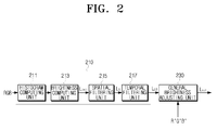
- FIG. 2 is a block diagram of a light emission control unit of a display apparatus according to an exemplary embodiment of the present invention
- FIG. 3 is a view provided for explaining a method for computing representative values of a light emission control unit of a display apparatus according to an exemplary embodiment of the present invention.
- the light emission control unit 200 includes the local brightness adjusting unit 210 which includes a histogram computing unit 211, a brightness computing unit 213, a spatial filtering unit 215 and a temporal filtering unit 217, and the general brightness adjusting unit 230.
- the histogram computing unit 211 computes a graylevel histogram with respect to a local area (k).
- Mathematical formula 1 represents that the largest value of the RGB pixels at coordinates (i,j) is selected as the brightness for the pixel at coordinates (i,j).
- a graylevel histogram is computed, based on the brightness of the pixels included in one local area (k).
- the histogram computing unit 211 computes a graylevel histogram using mathematical formula 1, with respect to all the (1024 ⁇ 768) local areas of the screen.
- the spatial filtering unit 215 spatially filters the initial representative value L init , and outputs the result.
- initial representative values L init By applying initial representative values L init to each of the local areas of the light emitting unit 400, blocking artefacts are generated in a still image due to different brightness of the local areas.
- the initial representative values L init are spatially filtered through the spatial low pass filter to remove the blocking artifacts, and as a result, a filtered, representative value L s is output.
- the temporal filtering unit 217 temporally filters the spatially-filtered representative value L s .
- the spatially filtered representative value L s is applied to the local areas of the light emitting unit 400, flickering occurs in the motion image due to the different brightness of the local areas.
- the spatially filtered representative value L s is thus temporally filtered through a temporal low pass filter to remove the flickering. As a result, a temporally filtered representative value L LD is output.
- the general brightness adjusting unit 230 adjusts the overall brightness of the screen, using mathematical formula 3, according to the R'G'B' pixels which are compensated and output from the local pixel compensating unit 310.
- L out k R GD * L LD k
- L out (k) denotes a final value for adjusting the brightness of the illuminating element(s) of the local area (k)
- R GD denotes a ratio for adjusting the entire screen.
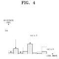
- FIG. 4 is a view provided for explaining a method for adjusting brightness of entire screen by a light emission control unit of a display apparatus according to an exemplary embodiment of the present invention.
- the brightness of the entire screen is adjusted at the same ratio R, and the ratio R is expressed by mathematical formula 4:
- R GD A / A + Thr ⁇ 2 * 255 - A
- R GD denotes a ratio to adjust the overall brightness of the entire screen in a uniform manner
- A denotes a cut-off graylevel, which is the maximum graylevel of the pixels of a local area excluding white Gaussian noise
- Thr2 denotes a threshold of 0-1.
- FIG. 5 is a block diagram of a panel control unit of a display apparatus according to an exemplary embodiment of the present invention
- FIGS. 6 to 9 are views provided for explaining a method for compensating pixel values of a panel control unit of a display apparatus according to an exemplary embodiment of the present invention.
- the panel control unit 300 includes the local pixel compensating unit 310 including a brightness estimating unit 311, a first LUT storage unit 314, a brightness interpolating unit 313, a second LUT storage unit 314, a compensation coefficient computing unit 315, a pixel compensating unit 316, and a dithering unit 317, and the general pixel compensating unit 330.
- the local pixel compensating unit 310 including a brightness estimating unit 311, a first LUT storage unit 314, a brightness interpolating unit 313, a second LUT storage unit 314, a compensation coefficient computing unit 315, a pixel compensating unit 316, and a dithering unit 317, and the general pixel compensating unit 330.
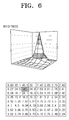
- the first LUT storage unit 314 stores the optical profile data as a lookup table as illustrated in FIG. 5 .
- FIG. 6 shows optical profile data which is measured from the centre of each of the local areas, when a local area (k) is in on state, while all the other local areas are in off state. As illustrated in FIG. 6 , the local area in on state has the greatest brightness, and the brightness gradually decreases towards the local areas farther away from the local area in on state.
- the brightness interpolating unit 313 interpolates (i, j)th pixel of each local area, using the estimate brightness (f E ).
- the representative value L LD output from the local brightness adjusting unit 210 is applied by the light emitting unit 400, the local areas each has the estimate brightness (f E ) as illustrated in FIG. 7 , and as a result, blocking artefacts occur.
- an interpolated pixel (f b ) of the (i, j)th pixel is computed to prevent the generating of the blocking artefacts, by applying bi-cubic interpolation or bi-linear interpolation to the estimate brightness (f E ).
- the second LUT storage unit 314 stores lookup tables as the exemplary ones illustrated in FIGS. 8A and 8B .
- the second LUT storage unit 314 stores a first lookup table (LUT BLU ) for compensating the interpolated pixel (f b ) of the (i, j)th pixel, and a second lookup table LUT GRAY for compensating a brightness Y of the (i, j)th pixel.
- LUT BLU first lookup table
- LUT GRAY for compensating a brightness Y of the (i, j)th pixel.
- f c (i, j) denotes a compensation coefficient of the (i, j)th pixel
- Thr denotes a parameter for controlling a compensation gain
- f b (i, j) denotes an interpolated brightness of the (i, j)th pixel
- LUT BLU (f b (i, j) denotes an interpolated f b (i, j) based on the lookup table
- Y(i, j) max(R(i, j), G(i, j), B(i, j))
- LUT GRAY (Y(i, j) denotes an interpolated value of Y(
- the pixel compensating unit 316 compensates the RGB pixel, using the compensation coefficient computed at the compensation coefficient computing unit 315 and mathematical formula below, and outputs a R'G'B' pixel:
- f c denotes a compensation coefficient for a RGB pixel.
- the smaller value is selected from among 255 and the pixel compensated by the compensation coefficient, so that the R'G'B' pixel does not exceed the maximum brightness, that is, 255, and cause saturation of an image.
- the dithering unit 317 dithers the R'G'B' pixel being output from the pixel compensating unit 316 and outputs the result.
- An image generally has a contour artifact when it is represented using the R'G'B' pixel output from the pixel compensating unit 316, but the contour artifact is removed by the dithering.
- the general pixel compensating unit 330 compensates the overall brightness of the screen, which is changed by the general brightness adjusting unit 230, using the dithered R'G'B' pixel from the dithering unit 317.
- a smaller pixel is selected from among 255 and a pixel which is compensated by the coefficient, such that the R"G"B" pixel does not exceed the maximum brightness, that is, 255 and cause saturation of an image.
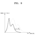
- Rre may be computed by incorporating a ratio R GD , which is the ratio used to adjust the overall brightness of the screen in a uniform manner, to mathematical formula (see FIG. 9 ):
- R re f IIR 1 / R GD ⁇
- f IIR denotes an Infinite Impulse Response (IIR) low pass filter
- ⁇ denotes a gamma compensation coefficient.
- FIG. 10 is a flowchart of a method for adjusting brightness of a display apparatus according to an exemplary embodiment of the present invention.
- the local brightness adjusting unit 210 computes a representative value L LD of each local area (S600).
- the representative values L LD are adjustment values which are used to control the light emitting unit 400 in each of local areas to provide the panel unit 500 with a light, according to the size of the RGB pixels for the respective local areas of the incoming signal.
- the local pixel compensating unit 310 computes a R'G'B' pixel, after compensating the loss of a video signal based on the representative value L LD (S620).
- L LD representative value
- a R'G'B' pixel is obtained from the incoming RGB pixel, by estimating the influence of adjusting the light emitting unit 400 in each of local areas using the representative values L LD .
- the general brightness adjusting unit 230 adjusts representative values L LD according to the R'G'B' pixels, and computes the final values Lout (S640). In particular, the general brightness adjusting unit 230 obtains the final values Lout, by adjusting the representative values L LD of the respective local areas based on the same ratio so that the overall brightness of the entire screen is adjusted according to the R'G'B' pixels, and outputs the final values Lout.
- the general pixel adjusting unit 330 then computes R"G"B" pixels, by compensating the brightness changes of the entire screen due to the final values Lout (S660). For example, if the light emitting unit 400 is controlled by the general brightness adjusting unit 230 to lower the overall brightness of the screen at the same ratio, the contrast ratio in the relatively dark areas would generally deteriorate. Accordingly, the R'G'B' pixels are compensated to R"G"B" pixels according to the ratio at which the representative values of the respective local areas are adjusted, so that the image can be represented with the brightness of the R'G'B' pixels.
Landscapes
- Engineering & Computer Science (AREA)
- Physics & Mathematics (AREA)
- General Physics & Mathematics (AREA)
- Computer Hardware Design (AREA)
- Theoretical Computer Science (AREA)
- Nonlinear Science (AREA)
- Crystallography & Structural Chemistry (AREA)
- Chemical & Material Sciences (AREA)
- Mathematical Physics (AREA)
- Optics & Photonics (AREA)
- Control Of Indicators Other Than Cathode Ray Tubes (AREA)
- Image Processing (AREA)
- Liquid Crystal Display Device Control (AREA)
- Facsimile Image Signal Circuits (AREA)
- Color Image Communication Systems (AREA)
- Television Receiver Circuits (AREA)
Applications Claiming Priority (1)
| Application Number | Priority Date | Filing Date | Title |
|---|---|---|---|
| KR1020070036065A KR101333680B1 (ko) | 2007-04-12 | 2007-04-12 | 디스플레이장치 및 그의 밝기 조정방법 |
Publications (2)
| Publication Number | Publication Date |
|---|---|
| EP1981015A2 true EP1981015A2 (fr) | 2008-10-15 |
| EP1981015A3 EP1981015A3 (fr) | 2011-05-25 |
Family
ID=39540392
Family Applications (1)
| Application Number | Title | Priority Date | Filing Date |
|---|---|---|---|
| EP08150901A Withdrawn EP1981015A3 (fr) | 2007-04-12 | 2008-01-31 | Appareil d'affichage et son procédé de réglage de la luminosité |
Country Status (5)
| Country | Link |
|---|---|
| US (1) | US8619102B2 (fr) |
| EP (1) | EP1981015A3 (fr) |
| JP (1) | JP5121464B2 (fr) |
| KR (1) | KR101333680B1 (fr) |
| CN (1) | CN101286300B (fr) |
Cited By (1)
| Publication number | Priority date | Publication date | Assignee | Title |
|---|---|---|---|---|
| US8624938B2 (en) | 2008-12-19 | 2014-01-07 | Semiconductor Energy Laboratory Co., Ltd. | Method for driving liquid crystal display device |
Families Citing this family (53)
| Publication number | Priority date | Publication date | Assignee | Title |
|---|---|---|---|---|
| US8358293B2 (en) * | 2008-04-29 | 2013-01-22 | Samsung Display Co., Ltd. | Method for driving light source blocks, driving unit for performing the method and display apparatus having the driving unit |
| US9041745B2 (en) * | 2008-06-03 | 2015-05-26 | Samsung Display Co., Ltd. | Method of boosting a local dimming signal, boosting drive circuit for performing the method, and display apparatus having the boosting drive circuit |
| KR101337076B1 (ko) * | 2008-10-07 | 2013-12-05 | 엘지디스플레이 주식회사 | 액정표시장치 및 그 구동 방법 |
| KR101536221B1 (ko) * | 2008-11-20 | 2015-07-14 | 삼성디스플레이 주식회사 | 픽셀 데이터 보상 방법, 이를 수행하기 위한 콘트롤러 유닛및 이를 갖는 표시 장치 |
| KR101539575B1 (ko) | 2009-01-28 | 2015-07-31 | 삼성디스플레이 주식회사 | 광원 구동 방법, 이를 수행하기 위한 광원 장치 및 이 광원장치를 포함하는 표시 장치 |
| WO2010089932A1 (fr) * | 2009-02-05 | 2010-08-12 | シャープ株式会社 | Dispositif d'affichage à cristaux liquides |
| WO2010090130A1 (fr) | 2009-02-06 | 2010-08-12 | Semiconductor Energy Laboratory Co., Ltd. | Procédé de pilotage de dispositif d'affichage |
| KR101605157B1 (ko) * | 2009-03-24 | 2016-03-22 | 삼성디스플레이 주식회사 | 표시 장치 구동 방법 |
| JP5448981B2 (ja) | 2009-04-08 | 2014-03-19 | 株式会社半導体エネルギー研究所 | 液晶表示装置の駆動方法 |
| KR101608856B1 (ko) | 2009-04-30 | 2016-04-05 | 삼성디스플레이 주식회사 | 디밍 구동 방법 및 이를 수행하기 위한 표시 장치 |
| JP5300601B2 (ja) * | 2009-06-01 | 2013-09-25 | キヤノン株式会社 | 表示装置、表示方法 |
| KR101581427B1 (ko) * | 2009-06-30 | 2015-12-31 | 삼성디스플레이 주식회사 | 표시 장치 및 그 구동 방법 |
| KR101612469B1 (ko) * | 2009-09-23 | 2016-04-15 | 삼성디스플레이 주식회사 | 광원 구동 방법 및 이를 수행하기 위한 표시 장치 |
| KR101318444B1 (ko) * | 2009-11-23 | 2013-10-16 | 엘지디스플레이 주식회사 | 픽셀 데이터 보상 방법과 이를 이용한 액정표시장치 |
| KR101588901B1 (ko) * | 2009-11-24 | 2016-02-12 | 엘지디스플레이 주식회사 | 액정표시장치 및 그의 로컬디밍 제어방법 |
| KR101623592B1 (ko) * | 2009-11-25 | 2016-05-24 | 엘지디스플레이 주식회사 | 액정표시장치 |
| KR101319352B1 (ko) * | 2009-12-11 | 2013-10-16 | 엘지디스플레이 주식회사 | 액정 표시 장치의 로컬 디밍 구동 방법 및 장치 |
| US9129565B2 (en) * | 2010-03-26 | 2015-09-08 | Hong Kong Applied Science and Technology Research Institute, Co. Ltd. | Adjusting a brightness level of a side emitting backlight display device using light spreading profiles |
| US8890793B2 (en) * | 2010-03-26 | 2014-11-18 | Hong Kong Applied Science and Technology Research Institute, Co. Ltd. | Adjusting a brightness level of a backlight of a display device |
| JP4783468B1 (ja) * | 2010-04-13 | 2011-09-28 | 株式会社東芝 | 輝度制御装置 |
| CN101814279B (zh) * | 2010-04-27 | 2012-10-03 | 上海易维视科技有限公司 | 动态背光液晶显示系统及方法 |
| JP5089783B2 (ja) | 2010-04-30 | 2012-12-05 | キヤノン株式会社 | 画像処理装置及びその制御方法 |
| JP2011242605A (ja) * | 2010-05-18 | 2011-12-01 | Sony Corp | 液晶表示装置 |
| JP5661336B2 (ja) * | 2010-05-28 | 2015-01-28 | 日立マクセル株式会社 | 液晶表示装置 |
| CN101877208B (zh) * | 2010-06-29 | 2013-07-03 | 彩虹集团公司 | 一种led背光源的控制方法 |
| KR101232086B1 (ko) * | 2010-10-08 | 2013-02-08 | 엘지디스플레이 주식회사 | 액정표시장치 및 그의 로컬디밍 제어방법 |
| CN102568386B (zh) * | 2010-12-29 | 2015-08-19 | 上海易维视科技有限公司 | 动态背光局部控制液晶显示方法及系统 |
| JP4897102B2 (ja) * | 2011-07-07 | 2012-03-14 | 株式会社東芝 | 輝度制御装置及び輝度制御方法 |
| CN102610197B (zh) * | 2012-01-04 | 2014-11-05 | 香港应用科技研究院有限公司 | 调整侧向发光式背光源显示装置的亮度级 |
| US9607556B2 (en) | 2012-06-15 | 2017-03-28 | Dolby Laboratories Licensing Corporation | Systems and methods for controlling dual modulation displays |
| KR102046429B1 (ko) * | 2012-11-30 | 2019-11-20 | 삼성디스플레이 주식회사 | 픽셀 휘도 보상 유닛, 이를 구비하는 평판 표시 장치 및 픽셀 휘도 커브 조절 방법 |
| CN103514853B (zh) * | 2013-09-23 | 2015-10-28 | 西安交通大学 | 一种应用于液晶显示动态调光的背光平滑方法及装置 |
| KR102105102B1 (ko) * | 2013-10-10 | 2020-04-27 | 삼성전자주식회사 | 디스플레이 장치 및 그 디스플레이 방법 |
| KR102136312B1 (ko) * | 2013-10-31 | 2020-07-22 | 엘지전자 주식회사 | 디스플레이 기기의 잔상방지장치 |
| KR102270207B1 (ko) * | 2014-11-27 | 2021-06-29 | 삼성디스플레이 주식회사 | 표시 장치 및 이의 구동 방법 |
| KR102281099B1 (ko) | 2014-12-10 | 2021-07-26 | 삼성디스플레이 주식회사 | 표시 장치, 이의 구동 방법 및 이를 위한 비젼 검사 장치 |
| US10419708B2 (en) * | 2015-04-20 | 2019-09-17 | Novatek Microelectronics Corp. | Image processing circuit and image contrast enhancement method thereof |
| CN105047145B (zh) * | 2015-09-14 | 2017-07-28 | 青岛海信电器股份有限公司 | 背光亮度控制方法、背光亮度控制装置及显示终端 |
| KR20180058266A (ko) * | 2016-11-23 | 2018-06-01 | 삼성디스플레이 주식회사 | 표시 장치 및 이의 휘도 보상 방법 |
| KR102646685B1 (ko) * | 2016-12-23 | 2024-03-13 | 삼성전자주식회사 | 디스플레이 장치 및 그 제어 방법 |
| KR102348064B1 (ko) * | 2017-07-28 | 2022-01-10 | 삼성디스플레이 주식회사 | 표시 장치 및 이의 구동 방법 |
| KR102550042B1 (ko) | 2018-05-25 | 2023-06-30 | 삼성전자주식회사 | 디스플레이를 통해 어플리케이션의 콘텐트를 표시하는 방법 및 이를 구현한 전자 장치 |
| CN108831374B (zh) | 2018-06-22 | 2020-06-30 | 京东方科技集团股份有限公司 | 像素点亮度补偿方法及装置 |
| CN108877694B (zh) * | 2018-08-06 | 2021-08-31 | 深圳创维-Rgb电子有限公司 | 一种双层液晶屏、背光亮度控制方法、装置及电子设备 |
| KR102529109B1 (ko) | 2018-08-07 | 2023-05-03 | 엘지디스플레이 주식회사 | 발광다이오드 및 전계발광 표시장치 |
| CN110956932B (zh) * | 2018-09-27 | 2021-01-29 | 京东方科技集团股份有限公司 | 显示设备及其驱动方法、驱动装置和计算机可读介质 |
| KR102577467B1 (ko) | 2018-11-02 | 2023-09-12 | 엘지디스플레이 주식회사 | 표시장치와 그 휘도 제어 방법 |
| JP7313287B2 (ja) | 2018-11-16 | 2023-07-24 | 京東方科技集團股▲ふん▼有限公司 | デュアル表示パネルに画像を表示するための方法及びその装置 |
| CN112825232B (zh) * | 2019-11-20 | 2023-01-06 | 华为技术有限公司 | 一种补偿方法及电子设备 |
| CN111883070B (zh) * | 2020-07-30 | 2021-09-10 | 重庆惠科金渝光电科技有限公司 | 一种显示面板的驱动方法、驱动模块和显示装置 |
| CN112542142B (zh) | 2020-12-02 | 2022-04-01 | Tcl华星光电技术有限公司 | 显示面板的补偿方法及其补偿装置 |
| KR102507174B1 (ko) * | 2022-10-18 | 2023-03-08 | 주식회사 티원엘에스 | 픽셀 데이터 변조를 통하여 소비전력을 절감하는 모니터 제어 장치 및 방법 |
| TW202542884A (zh) * | 2024-03-29 | 2025-11-01 | 日商索尼半導體解決方案公司 | 顯示系統及資訊處理方法 |
Citations (1)
| Publication number | Priority date | Publication date | Assignee | Title |
|---|---|---|---|---|
| US20050184952A1 (en) | 2004-02-09 | 2005-08-25 | Akitoyo Konno | Liquid crystal display apparatus |
Family Cites Families (7)
| Publication number | Priority date | Publication date | Assignee | Title |
|---|---|---|---|---|
| TWI285872B (en) | 1999-05-10 | 2007-08-21 | Matsushita Electric Industrial Co Ltd | Image display device and method for displaying image |
| JP4355977B2 (ja) | 1999-11-12 | 2009-11-04 | ソニー株式会社 | 映像表示装置および映像表示装置における照明制御方法 |
| US7394448B2 (en) | 2003-06-20 | 2008-07-01 | Lg. Display Co., Ltd | Method and apparatus for driving liquid crystal display device |
| KR20050028718A (ko) * | 2003-09-19 | 2005-03-23 | 엘지.필립스 엘시디 주식회사 | 액정표시장치 및 그의 구동방법 |
| GB2417816A (en) * | 2004-09-01 | 2006-03-08 | Drs Tactical Systems Inc | Low intensity displays compatible with night vision imaging systems |
| WO2007007472A1 (fr) | 2005-07-07 | 2007-01-18 | Sharp Kabushiki Kaisha | Unité d’affichage |
| TWI342002B (en) * | 2006-03-16 | 2011-05-11 | Novatek Microelectronics Corp | Apparatus and method for display backlight control |
-
2007
- 2007-04-12 KR KR1020070036065A patent/KR101333680B1/ko not_active Expired - Fee Related
-
2008
- 2008-01-07 JP JP2008000395A patent/JP5121464B2/ja not_active Expired - Fee Related
- 2008-01-18 US US12/016,245 patent/US8619102B2/en not_active Expired - Fee Related
- 2008-01-31 EP EP08150901A patent/EP1981015A3/fr not_active Withdrawn
- 2008-02-03 CN CN200810005713.1A patent/CN101286300B/zh not_active Expired - Fee Related
Patent Citations (1)
| Publication number | Priority date | Publication date | Assignee | Title |
|---|---|---|---|---|
| US20050184952A1 (en) | 2004-02-09 | 2005-08-25 | Akitoyo Konno | Liquid crystal display apparatus |
Cited By (8)
| Publication number | Priority date | Publication date | Assignee | Title |
|---|---|---|---|---|
| US8624938B2 (en) | 2008-12-19 | 2014-01-07 | Semiconductor Energy Laboratory Co., Ltd. | Method for driving liquid crystal display device |
| US8928706B2 (en) | 2008-12-19 | 2015-01-06 | Semiconductor Energy Laboratory Co., Ltd. | Method for driving liquid crystal display device |
| US9280937B2 (en) | 2008-12-19 | 2016-03-08 | Semiconductor Energy Laboratory Co., Ltd. | Method for driving liquid crystal display device |
| US10018872B2 (en) | 2008-12-19 | 2018-07-10 | Semiconductor Energy Laboratory Co., Ltd. | Method for driving liquid crystal display device |
| US10254586B2 (en) | 2008-12-19 | 2019-04-09 | Semiconductor Energy Laboratory Co., Ltd. | Method for driving liquid crystal display device |
| US10578920B2 (en) | 2008-12-19 | 2020-03-03 | Semiconductor Energy Laboratory Co., Ltd. | Method for driving liquid crystal display device |
| US11300832B2 (en) | 2008-12-19 | 2022-04-12 | Semiconductor Energy Laboratory Co., Ltd. | Method for driving liquid crystal display device |
| US11899311B2 (en) | 2008-12-19 | 2024-02-13 | Semiconductor Energy Laboratory Co., Ltd. | Method for driving liquid crystal display device |
Also Published As
| Publication number | Publication date |
|---|---|
| CN101286300A (zh) | 2008-10-15 |
| KR20080092581A (ko) | 2008-10-16 |
| JP2008263586A (ja) | 2008-10-30 |
| KR101333680B1 (ko) | 2013-12-02 |
| EP1981015A3 (fr) | 2011-05-25 |
| US20080252666A1 (en) | 2008-10-16 |
| JP5121464B2 (ja) | 2013-01-16 |
| US8619102B2 (en) | 2013-12-31 |
| CN101286300B (zh) | 2014-01-08 |
Similar Documents
| Publication | Publication Date | Title |
|---|---|---|
| EP1981015A2 (fr) | Appareil d'affichage et son procédé de réglage de la luminosité | |
| US9064459B2 (en) | Display apparatus and brightness adjusting method thereof | |
| KR101605157B1 (ko) | 표시 장치 구동 방법 | |
| CN100565290C (zh) | 液晶显示器和调节液晶显示器亮度的方法 | |
| US8643593B2 (en) | Method and apparatus of compensating image in a backlight local dimming system | |
| KR101608856B1 (ko) | 디밍 구동 방법 및 이를 수행하기 위한 표시 장치 | |
| US7317445B2 (en) | Motion blur decrease in varying duty cycle | |
| US8059082B2 (en) | Display device comprising an ajustable light source | |
| US8619017B2 (en) | Display device and display control method | |
| US8358293B2 (en) | Method for driving light source blocks, driving unit for performing the method and display apparatus having the driving unit | |
| US20100225574A1 (en) | Image display device and image display method | |
| US20040113906A1 (en) | Backlight dimming and LCD amplitude boost | |
| US20080042927A1 (en) | Display apparatus and method of adjusting brightness thereof | |
| EP2320412B1 (fr) | Dispositif d affichage d images et procédé d affichage d images | |
| US20110025728A1 (en) | Image processing apparatus and image display apparatus | |
| US20070285379A1 (en) | Liquid crystal display and method of adjusting brightness for the same | |
| US20120249610A1 (en) | Display device and display method therefor | |
| US9990878B2 (en) | Data clipping method using red, green, blue and white data, and display device using the same | |
| KR20160128729A (ko) | 영상 처리 방법 및 영상 처리 회로와 그를 이용한 표시 장치 | |
| CN100504981C (zh) | 用于减少图像的运动模糊的方法和设备 | |
| KR102510568B1 (ko) | 투명 표시 장치 및 그 구동 방법 | |
| KR101389359B1 (ko) | 디스플레이장치 및 그의 밝기 조정방법 | |
| US9443489B2 (en) | Gamma curve compensating method, gamma curve compensating circuit and display system using the same | |
| KR100759902B1 (ko) | 액정표시장치 및 그 밝기조정방법 | |
| US20110103708A1 (en) | Image processing apparatus and method of controlling the same |
Legal Events
| Date | Code | Title | Description |
|---|---|---|---|
| PUAI | Public reference made under article 153(3) epc to a published international application that has entered the european phase |
Free format text: ORIGINAL CODE: 0009012 |
|
| AK | Designated contracting states |
Kind code of ref document: A2 Designated state(s): AT BE BG CH CY CZ DE DK EE ES FI FR GB GR HR HU IE IS IT LI LT LU LV MC MT NL NO PL PT RO SE SI SK TR |
|
| AX | Request for extension of the european patent |
Extension state: AL BA MK RS |
|
| PUAL | Search report despatched |
Free format text: ORIGINAL CODE: 0009013 |
|
| AK | Designated contracting states |
Kind code of ref document: A3 Designated state(s): AT BE BG CH CY CZ DE DK EE ES FI FR GB GR HR HU IE IS IT LI LT LU LV MC MT NL NO PL PT RO SE SI SK TR |
|
| AX | Request for extension of the european patent |
Extension state: AL BA MK RS |
|
| 17P | Request for examination filed |
Effective date: 20111125 |
|
| AKX | Designation fees paid |
Designated state(s): DE GB NL |
|
| RAP1 | Party data changed (applicant data changed or rights of an application transferred) |
Owner name: SAMSUNG ELECTRONICS CO., LTD. |
|
| STAA | Information on the status of an ep patent application or granted ep patent |
Free format text: STATUS: THE APPLICATION IS DEEMED TO BE WITHDRAWN |
|
| 18D | Application deemed to be withdrawn |
Effective date: 20160802 |