EP1981000A2 - Procédé, appareil et programme d'affichage d'images - Google Patents
Procédé, appareil et programme d'affichage d'images Download PDFInfo
- Publication number
- EP1981000A2 EP1981000A2 EP08007214A EP08007214A EP1981000A2 EP 1981000 A2 EP1981000 A2 EP 1981000A2 EP 08007214 A EP08007214 A EP 08007214A EP 08007214 A EP08007214 A EP 08007214A EP 1981000 A2 EP1981000 A2 EP 1981000A2
- Authority
- EP
- European Patent Office
- Prior art keywords
- image
- dimensional structure
- cross
- dimensional
- range
- Prior art date
- Legal status (The legal status is an assumption and is not a legal conclusion. Google has not performed a legal analysis and makes no representation as to the accuracy of the status listed.)
- Withdrawn
Links
Images


Classifications
-
- G—PHYSICS
- G06—COMPUTING OR CALCULATING; COUNTING
- G06T—IMAGE DATA PROCESSING OR GENERATION, IN GENERAL
- G06T19/00—Manipulating three-dimensional [3D] models or images for computer graphics
-
- G—PHYSICS
- G06—COMPUTING OR CALCULATING; COUNTING
- G06T—IMAGE DATA PROCESSING OR GENERATION, IN GENERAL
- G06T2207/00—Indexing scheme for image analysis or image enhancement
- G06T2207/10—Image acquisition modality
- G06T2207/10072—Tomographic images
-
- G—PHYSICS
- G06—COMPUTING OR CALCULATING; COUNTING
- G06T—IMAGE DATA PROCESSING OR GENERATION, IN GENERAL
- G06T2207/00—Indexing scheme for image analysis or image enhancement
- G06T2207/10—Image acquisition modality
- G06T2207/10072—Tomographic images
- G06T2207/10088—Magnetic resonance imaging [MRI]
-
- G—PHYSICS
- G06—COMPUTING OR CALCULATING; COUNTING
- G06T—IMAGE DATA PROCESSING OR GENERATION, IN GENERAL
- G06T2207/00—Indexing scheme for image analysis or image enhancement
- G06T2207/30—Subject of image; Context of image processing
- G06T2207/30004—Biomedical image processing
- G06T2207/30101—Blood vessel; Artery; Vein; Vascular
Definitions
- the present invention relates to an image display method, apparatus, and program for displaying a three-dimensional configuration of a tubular structure extracted from a three-dimensional image of a subject in an easy-to-observe manner. More specifically, the invention is directed to an image display method, apparatus, and program for displaying a three-dimensional configuration of a luminal structure, such as blood vessel, intestine, bronchial tube, or the like in a manner useful for observation.
- a luminal structure such as blood vessel, intestine, bronchial tube, or the like in a manner useful for observation.
- processing for extracting a three-dimensional structure such as a core line representing structural information of an observation target luminal structure from a three-dimensional medical image of a subject obtained by CT equipment, MRI machine, ultrasonic diagnostic equipment, or the like and displaying the structure in a form useful for observation is performed, in order to facilitate observation of a three-dimensional configuration of the luminal structure of the subject, such as blood vessel, intestine, bronchial tube, or the like.
- a method of simultaneously displaying an image, such as a volume rendering image in which the entirety of a three-dimensional structure of extracted core line or the like is rendered in superimposed manner, and a multi planar reconstruction (MPR) image that orthogonally intersects the three-dimensional image at a specified arbitrary position thereof with an indicator, such as a marker or the like, attached to the intersecting position is proposed as described, for example, in Patent Document 1.
- an image such as a volume rendering image in which the entirety of a three-dimensional structure of extracted core line or the like is rendered in superimposed manner
- MPR multi planar reconstruction
- a method for providing, for example, an image I 2 shown in Figure 11 is also known, in which the entirety of the extracted three-dimensional image S is superimposed on each of the cross-sectional images, and an indicator, such as a marker or the like, is attached to the intersecting position to enable an observer to easily understand to which position on the three-dimensional structure each cross-sectional image corresponds.
- the entirety of the extracted three-dimensional structure is superimposed on each cross-sectional image with an indicator, such as a marker or the like attached to the intersecting position, so that as the length of the extracted three-dimensional structure becomes long, or as the structure of the three-dimensional structure becomes complicated, the three-dimensional structure displayed in a superimposed manner becomes large, which hinders observation of a region of interest and observability is degraded.
- an indicator such as a marker or the like attached to the intersecting position
- an object of the present invention to provide an image display method and apparatus capable of improving observability of the three-dimensional configuration of a target object. It is a further obj ect of the present invention to provide a computer program product therefor.
- a first image display method of the present invention is a method including the steps of:
- a second image display method of the present invention is a method including the steps of:
- a range of a predetermined thickness from a cross-section represented by the cross-sectional image means a range of a predetermined distance in the directions orthogonal to the cross-section
- a range of a predetermined distance from a position where the three-dimensional structure is intersecting the cross-sectional image means a range of a predetermined distance in all directions from the intersecting position.
- First and second image display apparatuses of the present invention include a structure extraction means, a projection image generation means, and a display means respectively for performing the first and second image display methods respectively.
- First and second image display programs of the present invention are programs for causing a computer to perform the first and second image display method respectively.
- the step of generating a projection image may be a step of generating a projection image by projecting only a part of the entirety of the portion of the three-dimensional structure located within the range of the predetermined thickness or distance, the part continuing from a section of the three-dimensional structure intersecting the cross-sectional image within the range.
- a luminal or line-like three-dimensional structure is extracted from a three-dimensional image of a target object, then a projection image is generated by projecting a portion of the entirety of the three-dimensional structure on a cross-sectional image of the target object intersecting the three-dimensional structure, the portion being a portion located within a range of a predetermined thickness from a cross-section represented by the cross-sectional image or a portion located within a range of a predetermined distance from a position where the three-dimensional structure is intersecting the cross-sectional image, and the generated projection image is displayed.
- this may provide a more suitable image for observation, in which only a limited region of interest of the three-dimensional structure is superimposed, which may improve observability of the three-dimensional configuration of a target object.
- Figure 1 is a hardware configuration diagram of a three-dimensional medical image processing system, illustrating an overview thereof. As illustrated, the system includes a modality 1, an image storage server 2, and an image processing workstation 3, which are communicatably connected with each other through a network 9.
- the modality 1 is used for obtaining a three-dimensional medical image V representing a subject, which is, more specifically, CT equipment, MRI machine, ultrasonic diagnostic equipment, or the like.
- the image storage server 2 is a computer for storing a three-dimensional medical image V obtained by the modality 1 and a medical image generated through image processing in the image processing workstation 3 in an image database and managing them.
- the image storage server 2 includes a large capacity external storage device, and database management software (e.g., ORDB (Object Relational Database) management software).
- database management software e.g., ORDB (Object Relational Database) management software.
- the image processing workstation 3 is a computer for performing image processing on a three-dimensional medical image V obtained from the modality 1 or the image storage server 2, and displaying the generated image in response to a request from a radiological reader.
- the image processing workstation 3, in particular, includes an input device, such as a keyboard, a mouse, or the like, for inputting a request from a radiological reader, a main storage unit having a sufficient capacity for storing the obtained three-dimensional medical image V, and a display for displaying the generated image.
- the image data storage format and communication between each unit through the network 9 are based on a protocol, such as DICOM (Digital Imaging and Communications in Medicine) or the like.
- DICOM Digital Imaging and Communications in Medicine
- FIG. 2 is a schematic block diagram of the image processing workstation 3, illustrating a schematic configuration thereof.
- the image processing workstation 3 includes an image obtaining means 10 for obtaining a three-dimensional medical image V including a target object (luminal structure) having a luminal structure, such as blood vessel, intestine, or bronchial tube from the modality 1 or image storage server 2 in response to a request from a radiological reader, a structure extraction means 20 for extracting a luminal or a line-like three-dimensional structure S of the target object from the obtained three-dimensional medical image V, a projection image generation means 30 for generating a projection image I by projecting a portion Sp of the entirety of the three-dimensional structure S located within a predetermined range R on a cross-sectional image P of the target object intersecting the three-dimensional structure S, and an image display means 40 for displaying the generated projection image I.
- a target object luminal structure
- a luminal structure such as blood vessel, intestine, or bronchial tube
- the image obtaining means 10 obtains a three-dimensional medical image V of a target patient for radiological reading which includes a target object (luminal structure) having a luminal structure, such as blood vessel, intestine, bronchial tube, or the like, from the modality 1 or image storage server 2 in response to a request from a radiological reader.
- the three-dimensional medical image V is constituted by multi slice images which are divided into voxels and arranged in a three-dimensional coordinate space.
- the structure extraction means 20 extracts a line-like or luminal three-dimensional structure S, such as a core line or an interface from the target object (luminal structure) having a luminal structure, such as blood vessel, intestine, bronchial tube, or the like, included in the three-dimensional image V.
- a line-like or luminal three-dimensional structure S such as a core line or an interface from the target object (luminal structure) having a luminal structure, such as blood vessel, intestine, bronchial tube, or the like, included in the three-dimensional image V.
- the search start point a determination is made as to whether or not each voxel within a region adjacent to the search point represents the target object, and with each voxel determined to represent the target object as a new search point, the search is performed in succession, thereby a smoothly curved area of the target object is obtained. Then, by thinning the obtained target object area or extracting the core line by the core line extraction method as described in Patent Document 1 described above, a line-like three-dimensional structure of the target object is extracted.
- the three-dimensional structure for example, may be a luminal structure that can be obtained by extracting an interface of the target object.
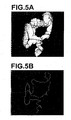
- Figures 3 , 4 , and 5 Examples of three-dimensional structures obtained through extraction by the structure extraction means 20 are shown in Figures 3 , 4 , and 5 .
- Figure 3B illustrates a three-dimensional structure of the coronary artery shown in Figure 3A
- Figure 4B illustrates a three-dimensional structure of the bronchial tubes shown in Figure 4A
- Figure 5B illustrates a three-dimensional structure of the large intestine shown in Figure 5A .
- an arbitrary cross-sectional image P intersecting the three-dimensional structure S is obtained.
- a cross-sectional image orthogonally intersecting the three-dimensional structure S obtained by MPR (Multi Planar Reconstruction) method at an arbitrary point C on the three-dimensional structure S specified by a radiological reader through the input device, such as a keyboard or a mouse, may be used as the cross-sectional image P.
- a projection image I is generated, in which a portion Sp of the entirety of the three-dimensional structure S located within a predetermined range R is projected on the obtained cross-sectional image P. More specifically, as shown in Figure 7 , a portion Sp of the entire three-dimensional structure S located within a range R 1 of a predetermined thickness t from the cross-section represented by the cross-sectional image P is projected on the cross-sectional image P to generate the projection image I. Alternatively, as shown in Figure 8 , a portion Sp of the entirety of the three-dimensional structure S located within a range R 2 of a predetermined distance from the position C where the three-dimensional structure is intersecting the cross-sectional image P is projected on the cross-sectional image P to generate the projection image I.
- the thickness t or the distance r is used for determining the range of the three-dimensional structure S to be projected and superimposed on the cross-sectional image P, and can be arbitrarily set according to a desired size of projection range of the three-dimensional structure S.
- the appropriate value of the range R 1 is a thickness t around 1 cm including the cross-sectional image P.
- the value of the thickness t or the distance r may be set such that the greater the diameter of the three-dimensional structure at the position C where the three-dimensional structure S and the cross-section image P are intersecting with each other, the greater the value.
- an image more clearly showing the continuity of the three-dimensional structure of the target object may be provided by, for example, in the following manner. That is, as shown in Figure 9 , of the entirety of the portion of the three-dimensional structure S located within a predetermined range R (a predetermined thickness range R1 or a predetermined distance range R2), only a part Sq continuing from a section of the three-dimensional structure S intersecting the cross-sectional image P within the range R is projected on the cross-sectional image P to generate a projection image I and the generated projection image I is displayed.
- a predetermined range R a predetermined thickness range R1 or a predetermined distance range R2
- the projection image I generated in the projection image generation means 30 is displayed on the display of the image processing workstation 3 by the image display means 40.
- a luminal or line-like three-dimensional structure S is extracted from a three-dimensional image V of a target object, then a projection image is generated by projecting a portion of the entirety of the three-dimensional structure on a cross-sectional image P of the target object intersecting the three-dimensional structure, the portion being a portion located within a range R 1 of a predetermined thickness from a cross-section represented by the cross-sectional image P, or a portion of the entirety of three-dimensional structure located within a range R 2 of a predetermined distance from a position where the three-dimensional structure is intersecting the cross-sectional image, and the generated projection image I is displayed.
- Figure 10 illustrates an example projection image I 2 displayed by the image display method of the present invention.
- Figure 10 clearly shows that the image I 2 is more suitable for observing a portion adjacent to the intersecting position between the three-dimensional structure and the cross-sectional image indicated by the marker in comparison with the image I 1 shown in Figure 11 , which is displayed by the conventional image display method in which the entirety of an extracted three-dimensional structure is superimposed on a cross-sectional image, since the portion adjacent to the intersecting position is not blocked by the superimposed three-dimensional structure in the image I 2 while it is blocked in the image I 1 .
- a projection image obtained by the present invention is displayed together with an image on which the entirety of a three-dimensional structure is superimposed which is generated by a volume rendering method or a maximum intensity projection method, and the intersecting state between the three-dimensional structure of the target object and a cross-sectional image is observed by referring to the entire shape of the three-dimensional structure.
Landscapes
- Engineering & Computer Science (AREA)
- General Physics & Mathematics (AREA)
- Computer Hardware Design (AREA)
- General Engineering & Computer Science (AREA)
- Software Systems (AREA)
- Physics & Mathematics (AREA)
- Computer Graphics (AREA)
- Theoretical Computer Science (AREA)
- Apparatus For Radiation Diagnosis (AREA)
- Magnetic Resonance Imaging Apparatus (AREA)
- Image Generation (AREA)
- Ultra Sonic Daignosis Equipment (AREA)
- Image Processing (AREA)
- Image Analysis (AREA)
Applications Claiming Priority (1)
| Application Number | Priority Date | Filing Date | Title |
|---|---|---|---|
| JP2007105271A JP4545169B2 (ja) | 2007-04-12 | 2007-04-12 | 画像表示方法、装置およびプログラム |
Publications (2)
| Publication Number | Publication Date |
|---|---|
| EP1981000A2 true EP1981000A2 (fr) | 2008-10-15 |
| EP1981000A3 EP1981000A3 (fr) | 2010-02-03 |
Family
ID=39650677
Family Applications (1)
| Application Number | Title | Priority Date | Filing Date |
|---|---|---|---|
| EP08007214A Withdrawn EP1981000A3 (fr) | 2007-04-12 | 2008-04-11 | Procédé, appareil et programme d'affichage d'images |
Country Status (3)
| Country | Link |
|---|---|
| US (1) | US8170328B2 (fr) |
| EP (1) | EP1981000A3 (fr) |
| JP (1) | JP4545169B2 (fr) |
Cited By (1)
| Publication number | Priority date | Publication date | Assignee | Title |
|---|---|---|---|---|
| EP2930695A1 (fr) * | 2014-03-28 | 2015-10-14 | Fujifilm Corporation | Appareil de configuration d'orientation tridimensionnelle, procédé et programme |
Families Citing this family (19)
| Publication number | Priority date | Publication date | Assignee | Title |
|---|---|---|---|---|
| JPWO2010055816A1 (ja) * | 2008-11-14 | 2012-04-12 | 株式会社日立メディコ | 超音波診断装置、超音波診断装置の規格画像データ生成方法 |
| EP2377095B1 (fr) * | 2008-12-10 | 2016-05-25 | Koninklijke Philips N.V. | Analyse de vaisseaux |
| JP5366713B2 (ja) * | 2009-08-25 | 2013-12-11 | 株式会社東芝 | 消化管画像表示装置及び消化管画像データ表示用制御プログラム |
| JP5606832B2 (ja) * | 2010-03-05 | 2014-10-15 | 富士フイルム株式会社 | 画像診断支援装置、方法およびプログラム |
| JP5537261B2 (ja) * | 2010-05-25 | 2014-07-02 | 株式会社東芝 | 医用画像診断装置、画像情報処理装置及び治療支援データ表示用制御プログラム |
| JPWO2012063653A1 (ja) * | 2010-11-12 | 2014-05-12 | 株式会社日立メディコ | 医用画像表示装置及び医用画像表示方法 |
| EP3164048B1 (fr) | 2014-07-02 | 2022-11-16 | Covidien LP | Informations en retour pour un enregistrement automatique en temps réel |
| US9603668B2 (en) | 2014-07-02 | 2017-03-28 | Covidien Lp | Dynamic 3D lung map view for tool navigation inside the lung |
| US9770216B2 (en) | 2014-07-02 | 2017-09-26 | Covidien Lp | System and method for navigating within the lung |
| US9530219B2 (en) | 2014-07-02 | 2016-12-27 | Covidien Lp | System and method for detecting trachea |
| US9754367B2 (en) | 2014-07-02 | 2017-09-05 | Covidien Lp | Trachea marking |
| CN106659453B (zh) | 2014-07-02 | 2020-05-26 | 柯惠有限合伙公司 | 用于分割肺部的系统和方法 |
| US20160000414A1 (en) | 2014-07-02 | 2016-01-07 | Covidien Lp | Methods for marking biopsy location |
| US10643371B2 (en) | 2014-08-11 | 2020-05-05 | Covidien Lp | Treatment procedure planning system and method |
| JP6293619B2 (ja) | 2014-08-28 | 2018-03-14 | ジーイー・メディカル・システムズ・グローバル・テクノロジー・カンパニー・エルエルシー | 画像処理方法および装置並びにプログラム |
| US10986990B2 (en) | 2015-09-24 | 2021-04-27 | Covidien Lp | Marker placement |
| US10709352B2 (en) | 2015-10-27 | 2020-07-14 | Covidien Lp | Method of using lung airway carina locations to improve ENB registration |
| US11224392B2 (en) | 2018-02-01 | 2022-01-18 | Covidien Lp | Mapping disease spread |
| US12089902B2 (en) | 2019-07-30 | 2024-09-17 | Coviden Lp | Cone beam and 3D fluoroscope lung navigation |
Citations (1)
| Publication number | Priority date | Publication date | Assignee | Title |
|---|---|---|---|---|
| WO2006127875A2 (fr) * | 2005-05-26 | 2006-11-30 | Siemens Corporate Research, Inc. | Procede et systeme destines a un examen bidimensionnel guide du colon |
Family Cites Families (16)
| Publication number | Priority date | Publication date | Assignee | Title |
|---|---|---|---|---|
| US5170347A (en) * | 1987-11-27 | 1992-12-08 | Picker International, Inc. | System to reformat images for three-dimensional display using unique spatial encoding and non-planar bisectioning |
| US5734384A (en) * | 1991-11-29 | 1998-03-31 | Picker International, Inc. | Cross-referenced sectioning and reprojection of diagnostic image volumes |
| US5782762A (en) * | 1994-10-27 | 1998-07-21 | Wake Forest University | Method and system for producing interactive, three-dimensional renderings of selected body organs having hollow lumens to enable simulated movement through the lumen |
| US6151404A (en) | 1995-06-01 | 2000-11-21 | Medical Media Systems | Anatomical visualization system |
| FR2795207B1 (fr) * | 1999-06-21 | 2001-08-17 | Ge Medical Syst Sa | Procede de visualisation d'une partie d'une image tridimensionnelle |
| US6643533B2 (en) | 2000-11-28 | 2003-11-04 | Ge Medical Systems Global Technology Company, Llc | Method and apparatus for displaying images of tubular structures |
| JP4675509B2 (ja) * | 2001-07-04 | 2011-04-27 | 株式会社日立メディコ | 臓器の特定領域抽出表示装置及び方法 |
| CN101219058B (zh) * | 2002-03-14 | 2012-01-11 | Netkisr有限公司 | 分析和显示计算机体层摄影术数据的系统和方法 |
| JP4129375B2 (ja) * | 2002-08-13 | 2008-08-06 | 株式会社東芝 | 医用画像診断装置および画像領域指定支援方法 |
| JP2004105256A (ja) * | 2002-09-13 | 2004-04-08 | Fuji Photo Film Co Ltd | 画像表示装置 |
| JP4421203B2 (ja) * | 2003-03-20 | 2010-02-24 | 株式会社東芝 | 管腔状構造体の解析処理装置 |
| WO2005055147A1 (fr) | 2003-12-02 | 2005-06-16 | Philips Intellectual Property & Standards Gmbh | Procede permettant de determiner la structure d'un objet en mouvement |
| JP4497965B2 (ja) * | 2004-03-17 | 2010-07-07 | 株式会社日立メディコ | 医用画像表示装置 |
| JP2006246941A (ja) * | 2005-03-08 | 2006-09-21 | Toshiba Corp | 画像処理装置及び管走行トラッキング方法 |
| US7586501B2 (en) * | 2005-05-24 | 2009-09-08 | Siemens Medical Solutions Usa, Inc. | Simultaneous projection of multi-branched vessels and their context on a single image |
| JP5085031B2 (ja) * | 2005-11-10 | 2012-11-28 | 株式会社東芝 | X線アンギオ撮影装置 |
-
2007
- 2007-04-12 JP JP2007105271A patent/JP4545169B2/ja active Active
-
2008
- 2008-04-10 US US12/100,860 patent/US8170328B2/en active Active
- 2008-04-11 EP EP08007214A patent/EP1981000A3/fr not_active Withdrawn
Patent Citations (1)
| Publication number | Priority date | Publication date | Assignee | Title |
|---|---|---|---|---|
| WO2006127875A2 (fr) * | 2005-05-26 | 2006-11-30 | Siemens Corporate Research, Inc. | Procede et systeme destines a un examen bidimensionnel guide du colon |
Cited By (1)
| Publication number | Priority date | Publication date | Assignee | Title |
|---|---|---|---|---|
| EP2930695A1 (fr) * | 2014-03-28 | 2015-10-14 | Fujifilm Corporation | Appareil de configuration d'orientation tridimensionnelle, procédé et programme |
Also Published As
| Publication number | Publication date |
|---|---|
| EP1981000A3 (fr) | 2010-02-03 |
| US20080253630A1 (en) | 2008-10-16 |
| JP4545169B2 (ja) | 2010-09-15 |
| US8170328B2 (en) | 2012-05-01 |
| JP2008259702A (ja) | 2008-10-30 |
Similar Documents
| Publication | Publication Date | Title |
|---|---|---|
| US8170328B2 (en) | Image display method, apparatus, and program | |
| US7620225B2 (en) | Method for simple geometric visualization of tubular anatomical structures | |
| JP5572440B2 (ja) | 診断支援システム、診断支援プログラムおよび診断支援方法 | |
| US8189888B2 (en) | Medical reporting system, apparatus and method | |
| US8786601B2 (en) | Generating views of medical images | |
| US8994720B2 (en) | Diagnosis assisting apparatus, diagnosis assisting program, and diagnosis assisting method | |
| US8306292B2 (en) | Image display device and image display program storage medium | |
| US20130195339A1 (en) | Image processing apparatus, imaging system, and image processing method | |
| WO2011122035A1 (fr) | Dispositif de génération d'image de projection, programme de génération d'image de projection, et procédé de génération d'image de projection | |
| HK1216049A1 (zh) | 为用户显示第一绘制投影和第二绘制投影之间的过渡的方法和系统 | |
| JP2017051591A (ja) | 情報処理装置及びその方法、情報処理システム、コンピュータプログラム | |
| JP2019103848A (ja) | 医用画像処理方法、医用画像処理装置、医用画像処理システム及び医用画像処理プログラム | |
| EP2495700A1 (fr) | Appareil d'assistance au diagnostic à base d'image, son procédé de fonctionnement et programme | |
| US9530238B2 (en) | Image processing apparatus, method and program utilizing an opacity curve for endoscopic images | |
| JP2013052245A (ja) | 情報処理装置および情報処理方法 | |
| EP2272427B1 (fr) | Dispositif, procédé et programme de traitement d'image | |
| EP2433570A1 (fr) | Système ultrasonore pour afficher une coupe d'objet et procédé associé | |
| US20190197762A1 (en) | Cpr image generation apparatus, method, and program | |
| JP5923067B2 (ja) | 診断支援装置および診断支援方法並びに診断支援プログラム | |
| EP2823764B1 (fr) | Dispositif, procédé et programme de traitement d'image médicale | |
| JP5518970B2 (ja) | 画像表示装置 | |
| JP5701208B2 (ja) | 医用画像表示装置及び医用画像表示方法 | |
| JP5491237B2 (ja) | 医用画像表示装置及び医用画像表示方法 | |
| US20060103678A1 (en) | Method and system for interactive visualization of locally oriented structures | |
| JP2017023834A (ja) | 画像処理装置、撮影システム及び画像処理方法 |
Legal Events
| Date | Code | Title | Description |
|---|---|---|---|
| PUAI | Public reference made under article 153(3) epc to a published international application that has entered the european phase |
Free format text: ORIGINAL CODE: 0009012 |
|
| AK | Designated contracting states |
Kind code of ref document: A2 Designated state(s): AT BE BG CH CY CZ DE DK EE ES FI FR GB GR HR HU IE IS IT LI LT LU LV MC MT NL NO PL PT RO SE SI SK TR |
|
| AX | Request for extension of the european patent |
Extension state: AL BA MK RS |
|
| PUAL | Search report despatched |
Free format text: ORIGINAL CODE: 0009013 |
|
| AK | Designated contracting states |
Kind code of ref document: A3 Designated state(s): AT BE BG CH CY CZ DE DK EE ES FI FR GB GR HR HU IE IS IT LI LT LU LV MC MT NL NO PL PT RO SE SI SK TR |
|
| AX | Request for extension of the european patent |
Extension state: AL BA MK RS |
|
| 17P | Request for examination filed |
Effective date: 20100802 |
|
| AKX | Designation fees paid |
Designated state(s): DE NL |
|
| 17Q | First examination report despatched |
Effective date: 20120330 |
|
| STAA | Information on the status of an ep patent application or granted ep patent |
Free format text: STATUS: THE APPLICATION IS DEEMED TO BE WITHDRAWN |
|
| 18D | Application deemed to be withdrawn |
Effective date: 20121010 |