EP1980771A2 - Stopperstruktur für eine Gangschaltung - Google Patents
Stopperstruktur für eine Gangschaltung Download PDFInfo
- Publication number
- EP1980771A2 EP1980771A2 EP08005841A EP08005841A EP1980771A2 EP 1980771 A2 EP1980771 A2 EP 1980771A2 EP 08005841 A EP08005841 A EP 08005841A EP 08005841 A EP08005841 A EP 08005841A EP 1980771 A2 EP1980771 A2 EP 1980771A2
- Authority
- EP
- European Patent Office
- Prior art keywords
- shift lever
- shift
- corner
- protruding
- stopper structure
- Prior art date
- Legal status (The legal status is an assumption and is not a legal conclusion. Google has not performed a legal analysis and makes no representation as to the accuracy of the status listed.)
- Withdrawn
Links
- 230000005540 biological transmission Effects 0.000 claims abstract description 14
- 230000002093 peripheral effect Effects 0.000 claims abstract description 6
- 230000007935 neutral effect Effects 0.000 description 4
Images

Classifications
-
- F—MECHANICAL ENGINEERING; LIGHTING; HEATING; WEAPONS; BLASTING
- F16—ENGINEERING ELEMENTS AND UNITS; GENERAL MEASURES FOR PRODUCING AND MAINTAINING EFFECTIVE FUNCTIONING OF MACHINES OR INSTALLATIONS; THERMAL INSULATION IN GENERAL
- F16H—GEARING
- F16H61/00—Control functions within control units of change-speed- or reversing-gearings for conveying rotary motion ; Control of exclusively fluid gearing, friction gearing, gearings with endless flexible members or other particular types of gearing
- F16H61/24—Providing feel, e.g. to enable selection
-
- F—MECHANICAL ENGINEERING; LIGHTING; HEATING; WEAPONS; BLASTING
- F16—ENGINEERING ELEMENTS AND UNITS; GENERAL MEASURES FOR PRODUCING AND MAINTAINING EFFECTIVE FUNCTIONING OF MACHINES OR INSTALLATIONS; THERMAL INSULATION IN GENERAL
- F16H—GEARING
- F16H59/00—Control inputs to control units of change-speed- or reversing-gearings for conveying rotary motion
- F16H59/02—Selector apparatus
- F16H59/04—Ratio selector apparatus
- F16H2059/047—Ratio selector apparatus with essentially straight linear movement for gear selection, e.g. straight selection movement using detent mechanism for improving feeling
-
- F—MECHANICAL ENGINEERING; LIGHTING; HEATING; WEAPONS; BLASTING
- F16—ENGINEERING ELEMENTS AND UNITS; GENERAL MEASURES FOR PRODUCING AND MAINTAINING EFFECTIVE FUNCTIONING OF MACHINES OR INSTALLATIONS; THERMAL INSULATION IN GENERAL
- F16H—GEARING
- F16H61/00—Control functions within control units of change-speed- or reversing-gearings for conveying rotary motion ; Control of exclusively fluid gearing, friction gearing, gearings with endless flexible members or other particular types of gearing
- F16H61/24—Providing feel, e.g. to enable selection
- F16H2061/243—Cams or detent arrays for guiding and providing feel
-
- F—MECHANICAL ENGINEERING; LIGHTING; HEATING; WEAPONS; BLASTING
- F16—ENGINEERING ELEMENTS AND UNITS; GENERAL MEASURES FOR PRODUCING AND MAINTAINING EFFECTIVE FUNCTIONING OF MACHINES OR INSTALLATIONS; THERMAL INSULATION IN GENERAL
- F16H—GEARING
- F16H59/00—Control inputs to control units of change-speed- or reversing-gearings for conveying rotary motion
- F16H59/02—Selector apparatus
- F16H59/04—Ratio selector apparatus
-
- Y—GENERAL TAGGING OF NEW TECHNOLOGICAL DEVELOPMENTS; GENERAL TAGGING OF CROSS-SECTIONAL TECHNOLOGIES SPANNING OVER SEVERAL SECTIONS OF THE IPC; TECHNICAL SUBJECTS COVERED BY FORMER USPC CROSS-REFERENCE ART COLLECTIONS [XRACs] AND DIGESTS
- Y10—TECHNICAL SUBJECTS COVERED BY FORMER USPC
- Y10T—TECHNICAL SUBJECTS COVERED BY FORMER US CLASSIFICATION
- Y10T74/00—Machine element or mechanism
- Y10T74/20—Control lever and linkage systems
- Y10T74/20012—Multiple controlled elements
- Y10T74/20018—Transmission control
- Y10T74/20177—Particular element [e.g., shift fork, template, etc.]
Definitions
- the present invention generally relates to a stopper structure of a shift lever adapted to be mounted to a shift operation apparatus for a transmission. Particularly, the present invention relates to a stopper structure of a shift lever for a manually operating transmission.
- the shift operation apparatus disclosed in the reference 1 includes a large sphere portion and a shift lever.
- a sphere of the large sphere portion is rotatably supported to a shift control retainer.
- the shift lever includes a small sphere portion which is selectively engaged with a head portion formed at a shift fork shaft.
- the shift lever is operated by being swung (pivotally moved), so that a selecting operation for the shift fork shaft is performed and then, a shifting operation for the shift fork shaft is performed.
- a shift stage of the transmission is changed.
- a pivotal movement of the shift lever may not be restrained even after the shift lever is shifted to a desired shift position.
- the pivotal movement (or a loose feeling) of the shift lever when being at a neutral position may not be stopped from occurring.
- a stopper structure of a shift lever which is pivotally movably supported and adapted to a shift operation apparatus for changing shift stages of a transmission by an operation of the shift lever, includes a protruding portion and a plurality of recessed portions.
- the protruding portion is formed at an outer peripheral portion of the shift lever.
- the plurality of recessed portions is formed at a member being stationary relative to the shift lever. Further, the plurality of recessed portions is formed to correspond to a shifting pattern and to be selectively and releaseably fitted by the protruding portion when the shift lever is shifted to a predetermined shift position.
- the protruding portion includes a corner portion formed at the outer peripheral portion of the shift lever, and the plurality of recessed portions includes a plurality of corner groove portions.
- the protruding portion includes a first protruding portion protruding in a first shifting direction of the shift lever and a second protruding portion protruding in a second shifting direction of the shift lever.
- the shift lever includes a rectangular cross sectional shape with a first corner protruding in a first shifting direction and a second corner protruding in a second shifting direction, each corner corresponding to the protruding portion.
- the shift lever when the shift lever is shifted in a predetermined shift stage, the shift lever is releaseably fitted into the member being stationary relative to the shift lever. Accordingly, the shift lever is restrained from pivotally moving in the shifting direction and/or in a selecting direction after being shifted to the predetermined shift position and a loose feeling may be prevented. Thus, loose vibration of the shift lever is restrained and further, a shifting mistake may be prevented from occurring.
- an intermediate portion of the shift lever is formed with a sphere portion rotatably supported by a shift control retainer.
- the member being stationary relative to the shift lever corresponds to a shift stopper formed with the plurality of recessed portions and assembled to be located above the sphere portion and to be positioned on an upper portion of the shift control retainer.
- the shift stopper formed with the plurality of recessed portions is assembled to be adjacent to the shift control retainer and the sphere portion. Therefore, a form of each recessed portion may be simplified. In addition, a structure, of the recessed portions, for fitting with the protruding portions of the shift lever may be readily adjusted.
- the member fixed relative to the shift lever includes one open end in a selecting direction of the shift lever, and the plurality of recessed portions are formed on an inner wall directed in a shifting direction so as to correspond to the shifting pattern.
- the member being stationary relative to the shift lever includes the open end in the selecting direction. Accordingly, the shift lever may be readily assembled to the shift operation apparatus.
- the member being stationary relative to the shift lever may be formed in a simple structure.
- Fig. 1 is a cross sectional view illustrating a stopper structure of a shift lever, according to an embodiment of the present invention
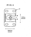
- Fig. 2 is a cross sectional view taken along line II-II of Fig. 1 , illustrating a state where the shift lever is positioned at a neutral position according to the embodiment;
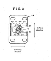
- Fig. 3 is an explanatory view illustrating states of the shift lever operated to each of shift stages.
- Fig. 1 is a cross sectional view illustrating the stopper structure of the shift lever 1, according to the embodiment.
- Fig. 2 is a cross sectional view taken along line II-II of Fig. 1 , illustrating a state where the shift lever 1 is positioned at a neutral position of the shift lever 1.
- Fig. 3 is an explanatory view illustrating states of the shift lever operated to each of shift positions. Additionally, in Figs. 2 and 3 , an upper and lower direction is referred to as a shifting direction of the shift lever 1 (including a first shifting direction and a second shifting direction), and a right and left direction is referred to as a selecting direction of the shift lever 1.
- the shift operation apparatus for shifting the shift stages (gears) of the transmission includes the shift lever 1, which is pivotally movably supported to a shift control retainer 3.
- the shift stages of the transmission are changed (shifted) by a shifting operation performed by means of the shift lever 1.
- the stopper structure of the shift lever 1 includes corner portions (each serving as a protruding portion) 1a and 1b, and plural corner groove portions (serving as a plurality of recessed portions) 1ST, 2ND, 3RD, 4TH, 5TH, 6TH and REV (see Fig. 3 ).
- the corner portions 1a and 1b are formed at an outer peripheral portion of the shift lever 1.
- the corner groove portions 1ST to 6TH and REV are formed at a shift stopper 4, which serves as a member being stationary relative to the shift lever 1, so as to correspond to a shifting pattern.
- the corner groove portions 1ST to 6TH and REV are formed to be fitted by the corner portions 1a and 1b.
- one of the corner groove portions 1ST to 6TH and REV is selectively and releasably engaged with one of the corner portions 1a and 1b.
- the shift lever 1 further includes an operation portion (not illustrated), a large sphere portion 2 and a small sphere portion (not illustrated).
- the operation portion is formed at one end of the shift lever 1.
- the large sphere portion 2 (serving as a sphere portion) is formed at an intermediate portion of the shift lever 1 and is rotatably supported by the shift control retainer 3.
- the small sphere portion is formed at another end of the shift lever 1 and is selectively engaged with a head (not illustrated) formed at a shift fork shaft (not illustrated). After a selecting operation is operated relative to shift fork shaft, a shifting operation is operated, thus changing the shift stages of the transmission.
- the corner portions 1a and 1b are respectively formed at the shift lever 1 and in the shifting direction thereof. More specifically, the shift lever 1 includes a rectangular cross sectional shape with a pair of corners protruding towards the shifting direction, i.e., in Fig. 2 , one corner of the shift lever 1 (serving as a first corner) protrudes upwardly (in the first shifting direction) and the other corner of the shift lever 1 (serving as a second corner) protrudes downwardly (in the second shifting direction).
- the pair of corners serves as the corner portions (protruding portions) 1a and 1b, i.e., the corner portion 1a serving as a first protruding portion and the corner portion 1b serving as a second protruding portion.
- the shift stopper 4 is assembled to be located above the large sphere portion 2 and to be positioned on an upper portion (top portion) of the shift control retainer 3.
- the shift stopper 4 includes one open end and another close end, both which are arranged in a selecting direction (i.e., a right side of the shift stopper 4).
- the plural corner groove portions 1ST to 6TH and RV are formed on an inner wall, of an opened portion, directed in the shifting direction so as to correspond to a shifting pattern (including a selecting pattern). More specifically, with reference to Figs.
- an upper side inner wall of the opened portion of the shift stopper 4 is formed with corner groove portions REV, 1ST, 3RD and 5TH, while a lower side inner wall of the opened portion of the shift stopper 4 is formed with corner groove portions 2ND, 4TH and 6TH.
- the shift stopper 4 formed with the corner groove portions 1ST to 6TH and REV is assembled to be adjacent to the shift control retainer 3 and the large sphere portion 2. Therefore, a form of each corner groove portion 1ST, 2ND, 3RD, 4TH, 5TH, 6TH and REV may be simplified. In addition, a structure, of the corner groove portions, for fitting with the corner portions 1a and 1b of the shift lever 1 may be readily adjusted.
- the shift stopper 4 includes the open end in the selecting direction. Accordingly, the shift lever 1 may be readily assembled to the shift operation apparatus. In addition, the shift stopper 4 may be formed in a simple structure.
Landscapes
- Engineering & Computer Science (AREA)
- General Engineering & Computer Science (AREA)
- Mechanical Engineering (AREA)
- Arrangement Or Mounting Of Control Devices For Change-Speed Gearing (AREA)
Applications Claiming Priority (1)
| Application Number | Priority Date | Filing Date | Title |
|---|---|---|---|
| JP2007102634A JP2008260328A (ja) | 2007-04-10 | 2007-04-10 | シフトレバーのストッパー構造 |
Publications (2)
| Publication Number | Publication Date |
|---|---|
| EP1980771A2 true EP1980771A2 (de) | 2008-10-15 |
| EP1980771A3 EP1980771A3 (de) | 2009-04-22 |
Family
ID=39636885
Family Applications (1)
| Application Number | Title | Priority Date | Filing Date |
|---|---|---|---|
| EP08005841A Withdrawn EP1980771A3 (de) | 2007-04-10 | 2008-03-27 | Stopperstruktur für eine Gangschaltung |
Country Status (3)
| Country | Link |
|---|---|
| US (1) | US20080250891A1 (de) |
| EP (1) | EP1980771A3 (de) |
| JP (1) | JP2008260328A (de) |
Cited By (1)
| Publication number | Priority date | Publication date | Assignee | Title |
|---|---|---|---|---|
| WO2016005554A3 (de) * | 2014-07-10 | 2016-03-03 | Marquardt Gmbh | Stellglied, insbesondere für ein kraftfahrzeug |
Families Citing this family (2)
| Publication number | Priority date | Publication date | Assignee | Title |
|---|---|---|---|---|
| USD744393S1 (en) | 2013-03-04 | 2015-12-01 | Richard D. Carroll | Gear shift blocker |
| KR101545090B1 (ko) | 2014-05-08 | 2015-08-18 | 현대다이모스(주) | 변속기의 점프아웃 방지장치 |
Citations (1)
| Publication number | Priority date | Publication date | Assignee | Title |
|---|---|---|---|---|
| JP2003097704A (ja) | 2001-09-26 | 2003-04-03 | Aisin Ai Co Ltd | シフト操作装置における異音発生防止機構 |
Family Cites Families (11)
| Publication number | Priority date | Publication date | Assignee | Title |
|---|---|---|---|---|
| US1212026A (en) * | 1916-05-23 | 1917-01-09 | Harvey R De Bra | Gear-shifting apparatus. |
| GB1179202A (en) * | 1967-09-21 | 1970-01-28 | Lucio Mansilla Albert Bollaert | Improvements in or relating to Remote Gearshift Mechanisms. |
| US3704982A (en) * | 1971-02-12 | 1972-12-05 | Hurst Performance | Stick shifter control for automatic transmission |
| JPS5259882U (de) * | 1975-10-29 | 1977-04-30 | ||
| US4116086A (en) * | 1976-11-26 | 1978-09-26 | Incom International, Inc. | Changeable gate plate means for lever control devices |
| DE3138827A1 (de) * | 1981-09-30 | 1983-04-14 | Wabco Westinghouse Fahrzeugbremsen GmbH, 3000 Hannover | Gangwaehler fuer ein getriebe |
| JPH0648052B2 (ja) * | 1984-11-21 | 1994-06-22 | 日野自動車工業株式会社 | トランスミッションの遠隔操作装置 |
| US5406860A (en) * | 1993-12-01 | 1995-04-18 | Deere & Company | Transmission shift lever assembly |
| US5799539A (en) * | 1997-01-21 | 1998-09-01 | Ford Global Technologies, Inc. | Manually shifted automatic transmission lever |
| US6230579B1 (en) * | 1999-11-17 | 2001-05-15 | Teleflex Incorporated | Multi-mode shifter assembly joint |
| JP2003291677A (ja) * | 2002-04-04 | 2003-10-15 | Kubota Corp | 変速操作装置 |
-
2007
- 2007-04-10 JP JP2007102634A patent/JP2008260328A/ja active Pending
-
2008
- 2008-03-27 EP EP08005841A patent/EP1980771A3/de not_active Withdrawn
- 2008-03-28 US US12/078,345 patent/US20080250891A1/en not_active Abandoned
Patent Citations (1)
| Publication number | Priority date | Publication date | Assignee | Title |
|---|---|---|---|---|
| JP2003097704A (ja) | 2001-09-26 | 2003-04-03 | Aisin Ai Co Ltd | シフト操作装置における異音発生防止機構 |
Cited By (2)
| Publication number | Priority date | Publication date | Assignee | Title |
|---|---|---|---|---|
| WO2016005554A3 (de) * | 2014-07-10 | 2016-03-03 | Marquardt Gmbh | Stellglied, insbesondere für ein kraftfahrzeug |
| US10865874B2 (en) | 2014-07-10 | 2020-12-15 | Marquardt Gmbh | Control element, in particular for a motor vehicle |
Also Published As
| Publication number | Publication date |
|---|---|
| US20080250891A1 (en) | 2008-10-16 |
| JP2008260328A (ja) | 2008-10-30 |
| EP1980771A3 (de) | 2009-04-22 |
Similar Documents
| Publication | Publication Date | Title |
|---|---|---|
| US8464601B2 (en) | Actuating device comprising a locking mechanism | |
| EP2203665B1 (de) | Mechanismus zur einstellung eines geschwindigkeitsänderungskabels eines manuellen getriebes | |
| US20080250891A1 (en) | Stopper structure of shift lever | |
| KR101499222B1 (ko) | 버튼형 전자식 변속레버 및 그 제어방법 | |
| US7654170B2 (en) | Centering spring apparatus for a transmission shift control mechanism | |
| EP2085664A3 (de) | Betriebsmechanismus eines Handschaltgetriebes | |
| JP2006266467A (ja) | 手動変速機 | |
| JP3170257B2 (ja) | 変速機のギヤシフト機構 | |
| CN102472385B (zh) | 包括变速器以及用于切换变速器挡位的选择元件的车辆 | |
| CN107218390B (zh) | 用于变速器的手动换挡操作用工具 | |
| JP2016002934A (ja) | トラクタ | |
| CN103557315A (zh) | 变速操纵器 | |
| KR102238079B1 (ko) | 하이브리드 변속 레버 | |
| KR20090102475A (ko) | 차량용 엠티 변속 레버 장치 | |
| JP2013137078A (ja) | 副変速機構付き変速機 | |
| KR101847300B1 (ko) | 수동 변속기의 셀렉트 방향 유격 보정 장치 | |
| JP4448824B2 (ja) | 自動シフト式手動変速機 | |
| KR20090081485A (ko) | 듀얼 클러치 변속기용 변속 액츄에이터의 인터락 장치 | |
| JP2010501403A5 (de) | ||
| KR100862462B1 (ko) | 자동차용 수동 변속기의 쉬프트 레버비 가변장치 | |
| KR101134283B1 (ko) | 핀 형태의 수동변속기 가이드 구조 | |
| KR100946505B1 (ko) | 수동 변속기의 디텐트 앗세이 | |
| KR100916201B1 (ko) | 수동변속기용 인터락바디 제어장치 | |
| KR100578758B1 (ko) | 수동변속기의 변속조작기구 | |
| KR100951798B1 (ko) | 수동변속기의 변속기구 |
Legal Events
| Date | Code | Title | Description |
|---|---|---|---|
| PUAI | Public reference made under article 153(3) epc to a published international application that has entered the european phase |
Free format text: ORIGINAL CODE: 0009012 |
|
| AK | Designated contracting states |
Kind code of ref document: A2 Designated state(s): AT BE BG CH CY CZ DE DK EE ES FI FR GB GR HR HU IE IS IT LI LT LU LV MC MT NL NO PL PT RO SE SI SK TR |
|
| AX | Request for extension of the european patent |
Extension state: AL BA MK RS |
|
| PUAL | Search report despatched |
Free format text: ORIGINAL CODE: 0009013 |
|
| AK | Designated contracting states |
Kind code of ref document: A3 Designated state(s): AT BE BG CH CY CZ DE DK EE ES FI FR GB GR HR HU IE IS IT LI LT LU LV MC MT NL NO PL PT RO SE SI SK TR |
|
| AX | Request for extension of the european patent |
Extension state: AL BA MK RS |
|
| 17P | Request for examination filed |
Effective date: 20090908 |
|
| 17Q | First examination report despatched |
Effective date: 20091008 |
|
| AKX | Designation fees paid |
Designated state(s): DE FR GB IT |
|
| STAA | Information on the status of an ep patent application or granted ep patent |
Free format text: STATUS: THE APPLICATION IS DEEMED TO BE WITHDRAWN |
|
| 18D | Application deemed to be withdrawn |
Effective date: 20100219 |