EP1979676B1 - Gasbrenner mit optimierter düsenanordnung - Google Patents
Gasbrenner mit optimierter düsenanordnung Download PDFInfo
- Publication number
- EP1979676B1 EP1979676B1 EP07702911A EP07702911A EP1979676B1 EP 1979676 B1 EP1979676 B1 EP 1979676B1 EP 07702911 A EP07702911 A EP 07702911A EP 07702911 A EP07702911 A EP 07702911A EP 1979676 B1 EP1979676 B1 EP 1979676B1
- Authority
- EP
- European Patent Office
- Prior art keywords
- gas
- nozzle
- primary
- burner
- accordance
- Prior art date
- Legal status (The legal status is an assumption and is not a legal conclusion. Google has not performed a legal analysis and makes no representation as to the accuracy of the status listed.)
- Not-in-force
Links
Images


Classifications
-
- F—MECHANICAL ENGINEERING; LIGHTING; HEATING; WEAPONS; BLASTING
- F23—COMBUSTION APPARATUS; COMBUSTION PROCESSES
- F23C—METHODS OR APPARATUS FOR COMBUSTION USING FLUID FUEL OR SOLID FUEL SUSPENDED IN A CARRIER GAS OR AIR
- F23C6/00—Combustion apparatus characterised by the combination of two or more combustion chambers or combustion zones, e.g. for staged combustion
- F23C6/04—Combustion apparatus characterised by the combination of two or more combustion chambers or combustion zones, e.g. for staged combustion in series connection
- F23C6/045—Combustion apparatus characterised by the combination of two or more combustion chambers or combustion zones, e.g. for staged combustion in series connection with staged combustion in a single enclosure
- F23C6/047—Combustion apparatus characterised by the combination of two or more combustion chambers or combustion zones, e.g. for staged combustion in series connection with staged combustion in a single enclosure with fuel supply in stages
-
- F—MECHANICAL ENGINEERING; LIGHTING; HEATING; WEAPONS; BLASTING
- F23—COMBUSTION APPARATUS; COMBUSTION PROCESSES
- F23D—BURNERS
- F23D14/00—Burners for combustion of a gas, e.g. of a gas stored under pressure as a liquid
- F23D14/46—Details
- F23D14/62—Mixing devices; Mixing tubes
- F23D14/64—Mixing devices; Mixing tubes with injectors
-
- F—MECHANICAL ENGINEERING; LIGHTING; HEATING; WEAPONS; BLASTING
- F23—COMBUSTION APPARATUS; COMBUSTION PROCESSES
- F23D—BURNERS
- F23D14/00—Burners for combustion of a gas, e.g. of a gas stored under pressure as a liquid
- F23D14/46—Details
- F23D14/70—Baffles or like flow-disturbing devices
-
- F—MECHANICAL ENGINEERING; LIGHTING; HEATING; WEAPONS; BLASTING
- F23—COMBUSTION APPARATUS; COMBUSTION PROCESSES
- F23D—BURNERS
- F23D2900/00—Special features of, or arrangements for burners using fluid fuels or solid fuels suspended in a carrier gas
- F23D2900/14—Special features of gas burners
- F23D2900/14003—Special features of gas burners with more than one nozzle
-
- F—MECHANICAL ENGINEERING; LIGHTING; HEATING; WEAPONS; BLASTING
- F23—COMBUSTION APPARATUS; COMBUSTION PROCESSES
- F23D—BURNERS
- F23D2900/00—Special features of, or arrangements for burners using fluid fuels or solid fuels suspended in a carrier gas
- F23D2900/14—Special features of gas burners
- F23D2900/14642—Special features of gas burners with jet mixers with more than one gas injection nozzles or orifices for a single mixing tube
Definitions
- the invention is directed to a gas burner for combustion of fuel gases with oxygen comprising a Primärgasdüse and secondary gas nozzles, which are connected to a common central supply line.
- a gas burner for combustion of fuel gases with oxygen comprising a Primärgasdüse and secondary gas nozzles, which are connected to a common central supply line.
- the obliquely downward non-horizontal openings of the primary gas nozzle are aligned so that the gas jet is directed to a point of a center line between two Sekundärgasdüsen, and the center line is defined as an imaginary line parallel to the axis of rotation of the Primärgasdüse and centrally between two adjacent secondary gas nozzles runs.
- stepped gas burners In the combustion of fuel gases or fuel gas mixtures, it is known in the art to use stepped gas burners.
- the fuel gas is discharged via the primary gas nozzles in a first combustion step in the combustion chamber or furnace chamber, mixed with oxygen or an oxygen-containing gas and burned.
- secondary gas nozzles are arranged downstream of the primary gas nozzles, which inject a further portion of fuel gas into the combustion chamber or furnace chamber and completely oxidize the oxidizable components in the gas mixture flowing past there. burn.
- a gas burner is, for example, off US 5 551 869 A known.
- Such gas burners are, for example, industrially used in ceiling-fired synthesis gas furnaces for the production of H 2 and CO.
- synthesis gas furnaces a multiplicity of reaction tubes filled with catalyst are passed through the furnace space fired from above.
- the reaction tubes arranged in lanes are heated by a plurality of stepped gas burners which fire into the gap between the lanes.
- the feed gas usually a lower hydrocarbon, such as methane, propane, butane or a mixture of these hydrocarbons. It is crucial that the reaction tubes are heated evenly. In regions of the catalyst-filled reaction tubes which are not heated to the required reaction temperature, no or reduced reaction takes place, whereby the total conversion of the synthesis process decreases. If local overheating occurs, there is a risk of material damage.
- the object of the invention is thus to provide an improved method and a gas burner are available, in which the reaction tubes are thermally stressed evenly as possible.
- a gas burner for combustion of fuel gases or fuel gas mixtures is disclosed together with oxygen or oxygen-containing gas mixtures comprising at least one primary gas nozzle and at least two secondary gas nozzles, which with a common central supply line are connected.
- the secondary gas nozzles are arranged substantially radially and symmetrically about the primary gas nozzle. Upstream of the primary gas nozzle at least one element for flow guidance is arranged.
- the Primärgasdüse has a plurality of radially arranged openings, wherein a part number of the openings are formed as horizontal openings whose axes perpendicular to the axis of rotation of the Primärgasdüse lead through the wall of the Primärgasdüse and the other part number are formed as non-horizontal openings whose axes in the direction provided Main flow direction are inclined towards the axis of rotation of the primary gas nozzle.
- axis of an opening should always be understood to mean the perpendicular to the free cross-sectional area of this opening, regardless of whether it is a round or differently shaped cross-sectional area.
- circular cross-sectional areas it should also be understood, with regard to the position of this axis in the cross-sectional area, that this axis passes through the center and, in the case of non-circular cross-sectional areas, that the axis passes through the geometric center of this cross-sectional area.
- Essential to the gas burner according to the invention is that the axes of each non-horizontal openings are directed to a point of a centerline between each two secondary gas nozzles, and the centerline is defined as an imaginary line parallel to the axis of rotation of the primary gas nozzle and centered between two adjacent secondary gas nozzles.
- the number of non-horizontal openings is identical to the number of secondary gas nozzles.
- An improved embodiment is that the secondary gas nozzles are arranged downstream of the primary gas nozzle.
- the gas burner can be optimized by the primary gas nozzle having one or more vertical openings, so that in the installed state, the fuel gas can flow in the direction of the axis of rotation.
- the gas burner head or the nozzle of the primary gas nozzle is a wearing part, which must be changed regularly. Therefore, an optimized variant is that the primary gas burner, a releasable nozzle head is provided, in which the non-horizontal openings are introduced, and the nozzle head is shaped or constructive elements are provided thereon, the axis of each non-horizontal opening at a point of Centerline is directed between two secondary gas nozzles.
- the nozzle could be fixed by means of a flange on the central tube and the position of the holes prevents misplacement of the openings.
- the gas burner head could be applied via a screw on the central tube and carried out by means of a spring-mounted ball, a Kontersplint or a lock screw fixing the final position.
- Other design variants are also conceivable.
- the gas burner can be further improved, in which an upstream of the primary gas nozzle arranged element for flow guidance is applied directly to the nozzle head or connected thereto.
- the invention further comprises a reforming furnace for producing hydrogen and carbon monoxide-containing synthesis gas, in which the gas burner according to one of the preceding embodiments is used. Also included in the invention is a process for the production of hydrogen and carbon monoxide-containing synthesis gas, in which a reforming furnace is provided with a gas burner according to one of the aforementioned embodiments.
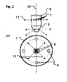
- Fig. 1 and Fig. 2 shows an example of the gas burner according to the invention.
- the invention is not limited to the embodiment shown.
- Fig. 1 shows a sketch of the gas burner according to the invention and the arrangement of primary and secondary gas nozzles in a perspective view.
- oxygen or an oxygen-containing gas mixture is passed via the channel 2.
- central fuel gas line 3 From the centrally located in the burner channel 1 central fuel gas line 3 branch off four smaller fuel gas lines 4, which lead to the Sekundärgasdüsen 5.
- These fuel gas lines 4 are arranged substantially symmetrically and lead radially from the central fuel gas line 3 to the outside and extend in a downward arc parallel to the wall of the burner channel 1 along, down.
- the secondary gas nozzles are arranged.
- a flow deflection 9 is arranged, which is formed in the present example as a screen.
- Fig. 1 the center line 10 shown between two downwardly directed fuel gas lines 4 as a dashed line.
- the center line 10 runs parallel to the central fuel gas line 3.
- the solder on the openings of the non-horizontal openings is directed precisely to this center line 10.
- This relationship has been outlined only for a non-horizontal opening 8, but applies to all other non-horizontal openings 8 in an analogous manner.
- the flow direction of the fuel gas from the non-horizontal opening 8 is sketched by the dashed arrow 11.
- Fig. 2 shows the detail view of the Primärgasdüse in an enlargement and in section AA, in the region of the non-horizontal openings 8.
- the gas burner jet which leaves the Primärgasdüse through the horizontal openings 7, perpendicular to the axis of rotation 12 of the central fuel gas line. 3 stands.
- This gas burner jet is indicated by the dashed arrow 13.
- dashed arrows 4 the direction of the gas burner gas that are passed through the non-horizontal openings 8 in the burner channel 1.
- Fig. 3a shows the use of the gas burner according to the invention, as in connection with Fig. 1 and Fig. 2 has been described.
- the distance from the primary gas nozzle in millimeters is plotted on the X-axis and the diagram areas represent areas with the same temperature.
- the temperature field of the device according to the invention was surprisingly homogeneous or uniformly stepped, as in Fig. 3a can be seen. There are no overheating or areas with very bad combustion. This leads to an optimal heating of adjacent reaction tubes and to a more complete combustion.
Landscapes
- Engineering & Computer Science (AREA)
- Chemical & Material Sciences (AREA)
- Combustion & Propulsion (AREA)
- Mechanical Engineering (AREA)
- General Engineering & Computer Science (AREA)
- Gas Burners (AREA)
- Pre-Mixing And Non-Premixing Gas Burner (AREA)
Applications Claiming Priority (2)
| Application Number | Priority Date | Filing Date | Title |
|---|---|---|---|
| DE102006005386A DE102006005386B4 (de) | 2006-02-03 | 2006-02-03 | Gasbrenner mit optimierter Düsenanordnung |
| PCT/EP2007/000483 WO2007090512A1 (de) | 2006-02-03 | 2007-01-20 | Gasbrenner mit optimierter düsenanordnung |
Publications (2)
| Publication Number | Publication Date |
|---|---|
| EP1979676A1 EP1979676A1 (de) | 2008-10-15 |
| EP1979676B1 true EP1979676B1 (de) | 2010-04-21 |
Family
ID=37943811
Family Applications (1)
| Application Number | Title | Priority Date | Filing Date |
|---|---|---|---|
| EP07702911A Not-in-force EP1979676B1 (de) | 2006-02-03 | 2007-01-20 | Gasbrenner mit optimierter düsenanordnung |
Country Status (11)
| Country | Link |
|---|---|
| US (1) | US20090224208A1 (da) |
| EP (1) | EP1979676B1 (da) |
| JP (1) | JP2009525452A (da) |
| CN (1) | CN101379346B (da) |
| AT (1) | ATE465375T1 (da) |
| CA (1) | CA2637762A1 (da) |
| DE (2) | DE102006005386B4 (da) |
| DK (1) | DK1979676T3 (da) |
| ES (1) | ES2344370T3 (da) |
| RU (1) | RU2008135671A (da) |
| WO (1) | WO2007090512A1 (da) |
Families Citing this family (4)
| Publication number | Priority date | Publication date | Assignee | Title |
|---|---|---|---|---|
| EP2085696A1 (en) * | 2008-01-31 | 2009-08-05 | Shell Internationale Research Maatschappij B.V. | Burner |
| EP2218965A1 (en) * | 2009-02-16 | 2010-08-18 | Total Petrochemicals Research Feluy | Low NOx burner |
| DE102012017785A1 (de) * | 2012-09-10 | 2014-03-13 | Thyssenkrupp Uhde Gmbh | Beladevorrichtung |
| US12158268B2 (en) | 2021-06-08 | 2024-12-03 | Forney Corporation | High-capacity igniter |
Family Cites Families (14)
| Publication number | Priority date | Publication date | Assignee | Title |
|---|---|---|---|---|
| US1696196A (en) * | 1922-04-21 | 1928-12-25 | James H Gray | Liquid-fuel burner |
| US1613611A (en) * | 1926-09-09 | 1927-01-11 | Cleveland Gas Burner & Applian | Gas burner |
| US1952356A (en) * | 1930-08-22 | 1934-03-27 | Foundry Equipment Company | Gas burner |
| US1960609A (en) * | 1932-04-04 | 1934-05-29 | Nels E Werner | Cross flame gas burner |
| US2365945A (en) * | 1942-03-07 | 1944-12-26 | Nat Airoil Burner Company Inc | Flame retention nozzle |
| US2614619A (en) * | 1947-10-22 | 1952-10-21 | Selas Corp Of America | Burner and nozzle tip for projecting hot products of combustion |
| CH298314A (fr) * | 1950-01-23 | 1954-04-30 | Bataafsche Petroleum | Brûleur à gaz. |
| US2805710A (en) * | 1951-03-13 | 1957-09-10 | Brumbaugh Isaac Vernon | Gas burner |
| US2817397A (en) * | 1951-04-10 | 1957-12-24 | Brumbaugh Isaac Vernon | Gas burner head having ribbed cap member provided with peripherally drilled ports |
| AT398477B (de) * | 1992-09-24 | 1994-12-27 | Vaillant Gmbh | Düsenplatte eines atmosphärischen gasbrenners |
| US5551869A (en) * | 1995-03-07 | 1996-09-03 | Brais, Martres Et Associes Inc. | Gas staged burner |
| DE19626240A1 (de) * | 1996-06-29 | 1998-01-02 | Abb Research Ltd | Vormischbrenner und Verfahren zum Betrieb des Brenners |
| DE19854382B4 (de) * | 1998-11-25 | 2009-01-02 | Alstom | Verfahren und Vorrichtung zur Zerstäubung flüssigen Brennstoffs für eine Feuerungsanlage |
| FR2788112B1 (fr) * | 1998-12-30 | 2001-06-08 | Total Raffinage Distribution | Appareil de type torchere et procede pour la combustion de gaz |
-
2006
- 2006-02-03 DE DE102006005386A patent/DE102006005386B4/de not_active Expired - Fee Related
-
2007
- 2007-01-20 EP EP07702911A patent/EP1979676B1/de not_active Not-in-force
- 2007-01-20 ES ES07702911T patent/ES2344370T3/es active Active
- 2007-01-20 WO PCT/EP2007/000483 patent/WO2007090512A1/de not_active Ceased
- 2007-01-20 CN CN2007800043240A patent/CN101379346B/zh not_active Expired - Fee Related
- 2007-01-20 AT AT07702911T patent/ATE465375T1/de active
- 2007-01-20 RU RU2008135671/06A patent/RU2008135671A/ru unknown
- 2007-01-20 US US12/223,558 patent/US20090224208A1/en not_active Abandoned
- 2007-01-20 DE DE502007003500T patent/DE502007003500D1/de active Active
- 2007-01-20 JP JP2008552715A patent/JP2009525452A/ja not_active Withdrawn
- 2007-01-20 CA CA002637762A patent/CA2637762A1/en not_active Abandoned
- 2007-01-20 DK DK07702911.4T patent/DK1979676T3/da active
Also Published As
| Publication number | Publication date |
|---|---|
| WO2007090512A1 (de) | 2007-08-16 |
| RU2008135671A (ru) | 2010-03-10 |
| US20090224208A1 (en) | 2009-09-10 |
| HK1130875A1 (en) | 2010-01-08 |
| JP2009525452A (ja) | 2009-07-09 |
| CN101379346B (zh) | 2012-06-27 |
| EP1979676A1 (de) | 2008-10-15 |
| ES2344370T3 (es) | 2010-08-25 |
| CN101379346A (zh) | 2009-03-04 |
| DE102006005386B4 (de) | 2009-04-09 |
| DE102006005386A1 (de) | 2007-08-16 |
| DK1979676T3 (da) | 2010-07-26 |
| CA2637762A1 (en) | 2007-08-16 |
| ATE465375T1 (de) | 2010-05-15 |
| DE502007003500D1 (de) | 2010-06-02 |
Similar Documents
| Publication | Publication Date | Title |
|---|---|---|
| DE2323382C3 (de) | Brenner für Schwefelwasserstoffgas | |
| DE102013100225B4 (de) | System für Brennstoffeinspritzung zur Vergasung | |
| DE19839085C2 (de) | Brenneranordnung mit primärem und sekundärem Pilotbrenner | |
| DE112015004429B4 (de) | Kraft-bzw. Brennstoffeinspritzdüse und Gasturbine | |
| DE60120674T2 (de) | Geschraubtes heizschild für die vorderseite einer brennerdüse | |
| EP1979676B1 (de) | Gasbrenner mit optimierter düsenanordnung | |
| DE102007040890A1 (de) | Kohlenstaubkombinationsbrenner mit integriertem Pilotbrenner | |
| DE10217913A1 (de) | Brennkammer mit flammenloser Oxidation | |
| WO2005095856A1 (de) | Katalytischer reaktor und verfahren zur verbrennung von brennstoff-luft-gemischen mittels eines katalytischen reaktors | |
| CH680084A5 (da) | ||
| DE60113792T2 (de) | Drallbrenner | |
| DD251476A3 (de) | Kohlenstaubbrenner | |
| EP2202460A2 (de) | Flachflammenbrenner und Verfahren zum Betreiben eines Flachflammenbrenners | |
| DE4231866C2 (de) | Brenner für Gas und Verfahren zum Verbrennen von Gas mit diesem Brenner | |
| EP3177743B1 (de) | Brenner-lanzen-einheit | |
| EP2252567A1 (de) | Verfahren und vorrichtung zur thermischen partiellen oxidation von kohlenwasserstoffen | |
| EP3038742B1 (de) | Vorrichtung und verfahren zum herstellen von acetylen und synthesegas | |
| EP1754937B1 (de) | Brennkopf und Verfahren zur Verbrennung von Brennstoff | |
| EP2846091B1 (de) | Oxy-gas burner with incandescent ignition | |
| DE69607224T2 (de) | Schwenkbarer Brenner mit Dichtung zur Erzeugung einer aufgeteilten Strömung | |
| EP1555484B1 (de) | Verfahren zum Betreiben einer Gasturbinen-Brennkammer | |
| WO2005026616A1 (de) | Verfahren und vorrichtung für die thermische abgasreinigung | |
| DE1468356A1 (de) | Verfahren und Vorrichtung zur partiellen Verbrennung eines paraffinischen Kohlenwasserstoffes zur Bildung von Acetylen | |
| DE2106074C3 (de) | Gasbrenner | |
| WO2016192833A1 (de) | Prozessbrenner und verfahren zum betreiben eines reaktors mit einem prozessbrenner |
Legal Events
| Date | Code | Title | Description |
|---|---|---|---|
| PUAI | Public reference made under article 153(3) epc to a published international application that has entered the european phase |
Free format text: ORIGINAL CODE: 0009012 |
|
| 17P | Request for examination filed |
Effective date: 20080630 |
|
| AK | Designated contracting states |
Kind code of ref document: A1 Designated state(s): AT BE BG CH CY CZ DE DK EE ES FI FR GB GR HU IE IS IT LI LT LU LV MC NL PL PT RO SE SI SK TR |
|
| RIN1 | Information on inventor provided before grant (corrected) |
Inventor name: GORVAL, EVGENI Inventor name: JOHANNING, JOACHIM Inventor name: WODBERG, SILKE |
|
| GRAP | Despatch of communication of intention to grant a patent |
Free format text: ORIGINAL CODE: EPIDOSNIGR1 |
|
| DAX | Request for extension of the european patent (deleted) | ||
| GRAS | Grant fee paid |
Free format text: ORIGINAL CODE: EPIDOSNIGR3 |
|
| GRAA | (expected) grant |
Free format text: ORIGINAL CODE: 0009210 |
|
| AK | Designated contracting states |
Kind code of ref document: B1 Designated state(s): AT BE BG CH CY CZ DE DK EE ES FI FR GB GR HU IE IS IT LI LT LU LV MC NL PL PT RO SE SI SK TR |
|
| REG | Reference to a national code |
Ref country code: GB Ref legal event code: FG4D Free format text: NOT ENGLISH |
|
| REG | Reference to a national code |
Ref country code: CH Ref legal event code: EP |
|
| REG | Reference to a national code |
Ref country code: CH Ref legal event code: NV Representative=s name: VALIPAT / PATENTS.EU S.A. C/O GUINNARD SA |
|
| REG | Reference to a national code |
Ref country code: IE Ref legal event code: FG4D Free format text: LANGUAGE OF EP DOCUMENT: GERMAN |
|
| REF | Corresponds to: |
Ref document number: 502007003500 Country of ref document: DE Date of ref document: 20100602 Kind code of ref document: P |
|
| REG | Reference to a national code |
Ref country code: DK Ref legal event code: T3 |
|
| REG | Reference to a national code |
Ref country code: NL Ref legal event code: T3 |
|
| REG | Reference to a national code |
Ref country code: ES Ref legal event code: FG2A Ref document number: 2344370 Country of ref document: ES Kind code of ref document: T3 |
|
| LTIE | Lt: invalidation of european patent or patent extension |
Effective date: 20100421 |
|
| PG25 | Lapsed in a contracting state [announced via postgrant information from national office to epo] |
Ref country code: SE Free format text: LAPSE BECAUSE OF FAILURE TO SUBMIT A TRANSLATION OF THE DESCRIPTION OR TO PAY THE FEE WITHIN THE PRESCRIBED TIME-LIMIT Effective date: 20100421 Ref country code: LT Free format text: LAPSE BECAUSE OF FAILURE TO SUBMIT A TRANSLATION OF THE DESCRIPTION OR TO PAY THE FEE WITHIN THE PRESCRIBED TIME-LIMIT Effective date: 20100421 |
|
| REG | Reference to a national code |
Ref country code: IE Ref legal event code: FD4D |
|
| PG25 | Lapsed in a contracting state [announced via postgrant information from national office to epo] |
Ref country code: SI Free format text: LAPSE BECAUSE OF FAILURE TO SUBMIT A TRANSLATION OF THE DESCRIPTION OR TO PAY THE FEE WITHIN THE PRESCRIBED TIME-LIMIT Effective date: 20100421 Ref country code: LV Free format text: LAPSE BECAUSE OF FAILURE TO SUBMIT A TRANSLATION OF THE DESCRIPTION OR TO PAY THE FEE WITHIN THE PRESCRIBED TIME-LIMIT Effective date: 20100421 Ref country code: IS Free format text: LAPSE BECAUSE OF FAILURE TO SUBMIT A TRANSLATION OF THE DESCRIPTION OR TO PAY THE FEE WITHIN THE PRESCRIBED TIME-LIMIT Effective date: 20100821 Ref country code: FI Free format text: LAPSE BECAUSE OF FAILURE TO SUBMIT A TRANSLATION OF THE DESCRIPTION OR TO PAY THE FEE WITHIN THE PRESCRIBED TIME-LIMIT Effective date: 20100421 |
|
| PG25 | Lapsed in a contracting state [announced via postgrant information from national office to epo] |
Ref country code: CY Free format text: LAPSE BECAUSE OF FAILURE TO SUBMIT A TRANSLATION OF THE DESCRIPTION OR TO PAY THE FEE WITHIN THE PRESCRIBED TIME-LIMIT Effective date: 20100602 Ref country code: PL Free format text: LAPSE BECAUSE OF FAILURE TO SUBMIT A TRANSLATION OF THE DESCRIPTION OR TO PAY THE FEE WITHIN THE PRESCRIBED TIME-LIMIT Effective date: 20100421 |
|
| PG25 | Lapsed in a contracting state [announced via postgrant information from national office to epo] |
Ref country code: IE Free format text: LAPSE BECAUSE OF FAILURE TO SUBMIT A TRANSLATION OF THE DESCRIPTION OR TO PAY THE FEE WITHIN THE PRESCRIBED TIME-LIMIT Effective date: 20100421 Ref country code: EE Free format text: LAPSE BECAUSE OF FAILURE TO SUBMIT A TRANSLATION OF THE DESCRIPTION OR TO PAY THE FEE WITHIN THE PRESCRIBED TIME-LIMIT Effective date: 20100421 Ref country code: PT Free format text: LAPSE BECAUSE OF FAILURE TO SUBMIT A TRANSLATION OF THE DESCRIPTION OR TO PAY THE FEE WITHIN THE PRESCRIBED TIME-LIMIT Effective date: 20100823 |
|
| PLBE | No opposition filed within time limit |
Free format text: ORIGINAL CODE: 0009261 |
|
| STAA | Information on the status of an ep patent application or granted ep patent |
Free format text: STATUS: NO OPPOSITION FILED WITHIN TIME LIMIT |
|
| PG25 | Lapsed in a contracting state [announced via postgrant information from national office to epo] |
Ref country code: SK Free format text: LAPSE BECAUSE OF FAILURE TO SUBMIT A TRANSLATION OF THE DESCRIPTION OR TO PAY THE FEE WITHIN THE PRESCRIBED TIME-LIMIT Effective date: 20100421 Ref country code: RO Free format text: LAPSE BECAUSE OF FAILURE TO SUBMIT A TRANSLATION OF THE DESCRIPTION OR TO PAY THE FEE WITHIN THE PRESCRIBED TIME-LIMIT Effective date: 20100421 Ref country code: CZ Free format text: LAPSE BECAUSE OF FAILURE TO SUBMIT A TRANSLATION OF THE DESCRIPTION OR TO PAY THE FEE WITHIN THE PRESCRIBED TIME-LIMIT Effective date: 20100421 |
|
| 26N | No opposition filed |
Effective date: 20110124 |
|
| PG25 | Lapsed in a contracting state [announced via postgrant information from national office to epo] |
Ref country code: GR Free format text: LAPSE BECAUSE OF FAILURE TO SUBMIT A TRANSLATION OF THE DESCRIPTION OR TO PAY THE FEE WITHIN THE PRESCRIBED TIME-LIMIT Effective date: 20100722 |
|
| BERE | Be: lapsed |
Owner name: UHDE G.M.B.H. Effective date: 20110131 |
|
| REG | Reference to a national code |
Ref country code: NL Ref legal event code: V1 Effective date: 20110801 |
|
| REG | Reference to a national code |
Ref country code: DK Ref legal event code: EBP |
|
| PG25 | Lapsed in a contracting state [announced via postgrant information from national office to epo] |
Ref country code: MC Free format text: LAPSE BECAUSE OF NON-PAYMENT OF DUE FEES Effective date: 20110131 |
|
| REG | Reference to a national code |
Ref country code: CH Ref legal event code: PL |
|
| GBPC | Gb: european patent ceased through non-payment of renewal fee |
Effective date: 20110120 |
|
| REG | Reference to a national code |
Ref country code: FR Ref legal event code: ST Effective date: 20110930 |
|
| PG25 | Lapsed in a contracting state [announced via postgrant information from national office to epo] |
Ref country code: LI Free format text: LAPSE BECAUSE OF NON-PAYMENT OF DUE FEES Effective date: 20110131 Ref country code: FR Free format text: LAPSE BECAUSE OF NON-PAYMENT OF DUE FEES Effective date: 20110131 Ref country code: CH Free format text: LAPSE BECAUSE OF NON-PAYMENT OF DUE FEES Effective date: 20110131 |
|
| PG25 | Lapsed in a contracting state [announced via postgrant information from national office to epo] |
Ref country code: GB Free format text: LAPSE BECAUSE OF NON-PAYMENT OF DUE FEES Effective date: 20110120 Ref country code: BE Free format text: LAPSE BECAUSE OF NON-PAYMENT OF DUE FEES Effective date: 20110131 |
|
| REG | Reference to a national code |
Ref country code: DE Ref legal event code: R119 Ref document number: 502007003500 Country of ref document: DE Effective date: 20110802 |
|
| PG25 | Lapsed in a contracting state [announced via postgrant information from national office to epo] |
Ref country code: IT Free format text: LAPSE BECAUSE OF NON-PAYMENT OF DUE FEES Effective date: 20110120 Ref country code: NL Free format text: LAPSE BECAUSE OF NON-PAYMENT OF DUE FEES Effective date: 20110801 |
|
| REG | Reference to a national code |
Ref country code: ES Ref legal event code: FD2A Effective date: 20120220 |
|
| PG25 | Lapsed in a contracting state [announced via postgrant information from national office to epo] |
Ref country code: ES Free format text: LAPSE BECAUSE OF NON-PAYMENT OF DUE FEES Effective date: 20110121 |
|
| REG | Reference to a national code |
Ref country code: AT Ref legal event code: MM01 Ref document number: 465375 Country of ref document: AT Kind code of ref document: T Effective date: 20120120 |
|
| PG25 | Lapsed in a contracting state [announced via postgrant information from national office to epo] |
Ref country code: LU Free format text: LAPSE BECAUSE OF NON-PAYMENT OF DUE FEES Effective date: 20110120 |
|
| PG25 | Lapsed in a contracting state [announced via postgrant information from national office to epo] |
Ref country code: AT Free format text: LAPSE BECAUSE OF NON-PAYMENT OF DUE FEES Effective date: 20120120 Ref country code: DE Free format text: LAPSE BECAUSE OF NON-PAYMENT OF DUE FEES Effective date: 20110802 |
|
| PG25 | Lapsed in a contracting state [announced via postgrant information from national office to epo] |
Ref country code: BG Free format text: LAPSE BECAUSE OF FAILURE TO SUBMIT A TRANSLATION OF THE DESCRIPTION OR TO PAY THE FEE WITHIN THE PRESCRIBED TIME-LIMIT Effective date: 20100721 Ref country code: TR Free format text: LAPSE BECAUSE OF FAILURE TO SUBMIT A TRANSLATION OF THE DESCRIPTION OR TO PAY THE FEE WITHIN THE PRESCRIBED TIME-LIMIT Effective date: 20100421 |
|
| PG25 | Lapsed in a contracting state [announced via postgrant information from national office to epo] |
Ref country code: HU Free format text: LAPSE BECAUSE OF FAILURE TO SUBMIT A TRANSLATION OF THE DESCRIPTION OR TO PAY THE FEE WITHIN THE PRESCRIBED TIME-LIMIT Effective date: 20100421 |