EP1978256A1 - Rotationsschlauchpumpe - Google Patents
Rotationsschlauchpumpe Download PDFInfo
- Publication number
- EP1978256A1 EP1978256A1 EP06833197A EP06833197A EP1978256A1 EP 1978256 A1 EP1978256 A1 EP 1978256A1 EP 06833197 A EP06833197 A EP 06833197A EP 06833197 A EP06833197 A EP 06833197A EP 1978256 A1 EP1978256 A1 EP 1978256A1
- Authority
- EP
- European Patent Office
- Prior art keywords
- roller
- pump
- roller pump
- elastic tube
- link member
- Prior art date
- Legal status (The legal status is an assumption and is not a legal conclusion. Google has not performed a legal analysis and makes no representation as to the accuracy of the status listed.)
- Granted
Links
Images


Classifications
-
- F—MECHANICAL ENGINEERING; LIGHTING; HEATING; WEAPONS; BLASTING
- F04—POSITIVE - DISPLACEMENT MACHINES FOR LIQUIDS; PUMPS FOR LIQUIDS OR ELASTIC FLUIDS
- F04B—POSITIVE-DISPLACEMENT MACHINES FOR LIQUIDS; PUMPS
- F04B43/00—Machines, pumps, or pumping installations having flexible working members
- F04B43/12—Machines, pumps, or pumping installations having flexible working members having peristaltic action
- F04B43/1253—Machines, pumps, or pumping installations having flexible working members having peristaltic action by using two or more rollers as squeezing elements, the rollers moving on an arc of a circle during squeezing
-
- A—HUMAN NECESSITIES
- A61—MEDICAL OR VETERINARY SCIENCE; HYGIENE
- A61M—DEVICES FOR INTRODUCING MEDIA INTO, OR ONTO, THE BODY; DEVICES FOR TRANSDUCING BODY MEDIA OR FOR TAKING MEDIA FROM THE BODY; DEVICES FOR PRODUCING OR ENDING SLEEP OR STUPOR
- A61M5/00—Devices for bringing media into the body in a subcutaneous, intra-vascular or intramuscular way; Accessories therefor, e.g. filling or cleaning devices, arm-rests
- A61M5/14—Infusion devices, e.g. infusing by gravity; Blood infusion; Accessories therefor
- A61M5/142—Pressure infusion, e.g. using pumps
- A61M5/14212—Pumping with an aspiration and an expulsion action
- A61M5/14232—Roller pumps
-
- F—MECHANICAL ENGINEERING; LIGHTING; HEATING; WEAPONS; BLASTING
- F04—POSITIVE - DISPLACEMENT MACHINES FOR LIQUIDS; PUMPS FOR LIQUIDS OR ELASTIC FLUIDS
- F04C—ROTARY-PISTON, OR OSCILLATING-PISTON, POSITIVE-DISPLACEMENT MACHINES FOR LIQUIDS; ROTARY-PISTON, OR OSCILLATING-PISTON, POSITIVE-DISPLACEMENT PUMPS
- F04C5/00—Rotary-piston machines or pumps with the working-chamber walls at least partly resiliently deformable
-
- A—HUMAN NECESSITIES
- A61—MEDICAL OR VETERINARY SCIENCE; HYGIENE
- A61M—DEVICES FOR INTRODUCING MEDIA INTO, OR ONTO, THE BODY; DEVICES FOR TRANSDUCING BODY MEDIA OR FOR TAKING MEDIA FROM THE BODY; DEVICES FOR PRODUCING OR ENDING SLEEP OR STUPOR
- A61M60/00—Blood pumps; Devices for mechanical circulatory actuation; Balloon pumps for circulatory assistance
- A61M60/10—Location thereof with respect to the patient's body
- A61M60/104—Extracorporeal pumps, i.e. the blood being pumped outside the patient's body
- A61M60/109—Extracorporeal pumps, i.e. the blood being pumped outside the patient's body incorporated within extracorporeal blood circuits or systems
- A61M60/113—Extracorporeal pumps, i.e. the blood being pumped outside the patient's body incorporated within extracorporeal blood circuits or systems in other functional devices, e.g. dialysers or heart-lung machines
-
- A—HUMAN NECESSITIES
- A61—MEDICAL OR VETERINARY SCIENCE; HYGIENE
- A61M—DEVICES FOR INTRODUCING MEDIA INTO, OR ONTO, THE BODY; DEVICES FOR TRANSDUCING BODY MEDIA OR FOR TAKING MEDIA FROM THE BODY; DEVICES FOR PRODUCING OR ENDING SLEEP OR STUPOR
- A61M60/00—Blood pumps; Devices for mechanical circulatory actuation; Balloon pumps for circulatory assistance
- A61M60/20—Type thereof
- A61M60/247—Positive displacement blood pumps
- A61M60/253—Positive displacement blood pumps including a displacement member directly acting on the blood
- A61M60/268—Positive displacement blood pumps including a displacement member directly acting on the blood the displacement member being flexible, e.g. membranes, diaphragms or bladders
- A61M60/279—Peristaltic pumps, e.g. roller pumps
Definitions
- the present invention relates to a roller pump that delivers liquid such as blood, dialysis fluids, or medicines by pressingly closing an elastic tube using a roller rotating device. More particularly, the present invention relates to a roller pump suitable for medical applications.
- a dialysis apparatus performing such a blood purification method or a blood artificial dialysis generally delivers liquid contained in an elastic tube by mounting a roller pump in a liquid circuit.
- roller pump having a conventional structure of sliding and spreading a pump housing thereby improving efficiency of installing/removing of a tube in/from the roller pump.
- an operation lever is reciprocated between an opened position and a closed position to drive a stator forwards/afterwards, arm parts are moved along guide holes to install/remove a tube.
- roller pump disclosed in Patent Reference 1 has a problem that, while improving the efficiency of tube installing/removing, the increase of the number of parts makes it difficult to strictly ensure an interval precision between the pump housing and a roller, which fails to control a discharging flow rate of a fluid at high accuracy.
- the present invention overcomes the above problem. It is an object of the present invention to provide a roller pump in/from which an elastic tube can be easily installed and removed, and which surely prevents the elastic tube from being accidentally released from the roller pump when the elastic tube should be set in the roller pump. It is another object of the present invention to provide a roller pump that can control a discharging flow rate at high accuracy, by ensuring an interval precision between (i) a slide part restricting an arrangement of the elastic tube and (ii) a roller.
- a roller pump that delivers a fluid contained in an elastic tube by pressingly closing the elastic tube using a roller of a roller rotating device positioned on a base
- the roller pump including: a slide part that is movable to a direction of the roller, and restricts an arrangement of the elastic tube; an operation part that operates (i) an opened state of the slide part where the elastic tube is installed in or removed from the roller pump, or (ii) a closed state of the slide part where the elastic tube is held in the roller pump; and an inhibit part that inhibits the slide part from moving to the opened state without the operation of the operation part, when the slide part is in the closed state.
- the roller pump according to the present invention can ensure an appropriate interval precision between the slide part as a housing and the roller. As a result, the roller pump according to the present invention can control a discharging flow rate of the fluid at high accuracy.
- the inhibit part may include a first link member and a second link member which are in contact with each other by respective substantially circular contact surfaces, the first link member has: one end rotatably connected to the slide part: and an other end rotatably connected to the second link member, and the second link member has: one end rotatably connected to the first link member: and an other end rotatably connected to a fixed part on the base, and a contact point between the first link member and the second link member exceeds a dead point of the second link member, when the slide part is changed from the opened state to the closed state.
- the roller pump can prevent that the elastic tube is accidentally released from the roller pump while the roller pump operates.
- roller pump according to the present invention a slide part in slide-ably contact with an elastic tube slides to and from the elastic tube, so that the elastic tube can be easily set in the roller pump. Furthermore, the roller pump according to the present invention can ensure an appropriate interval precision between (i) the slide part restricting an arrangement of the elastic tube and (ii) a roller. Thereby, the roller pump according to the present invention can control a discharging flow rate at high accuracy, and can surely prevent the elastic tube from being accidentally released from the roller pump while the elastic tube should be set in the roller pump.
- FIG. 1 is a perspective view of a dialysis apparatus using a roller pump according to a preferred embodiment of the present invention.
- a dialysis apparatus that performs blood artificial dialysis includes: a liquid circuit body 100; and a dialysis apparatus body 200 having a driving unit that circulates liquid into the liquid circuit.
- this dialysis apparatus uses, for example, a roller pump 40 that will be described later with reference to FIG. 4 .
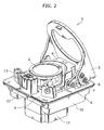
- FIG. 2 is a perspective view of a roller pump 1 according to an embodiment of the present invention.
- the roller pump 1 according to the present embodiment is characterized in including a pump slide 4 that has a wall surface in slide-ably contact with an elastic tube and slides to and from the elastic tube, which makes it easy to install and remove the elastic tube in/from the roller pump 1. Furthermore, the roller pump 1 according to the present embodiment is characterized in having slider links 6 and 7 that inhibit undesired opening (an opened state) of the pump slide 4 when the elastic tube should be hold in the roller pump 1.
- the roller pump 1 includes a roller head 2, rollers 3, a pump slide 4, a pump block cover 5, a first slider link 6, a second slider link 7, a pump block base 9, a base 10, a motor 11, a cover lock 12, and tube guides 13.
- the roller head 2 is a roller rotating device that is connected to the motor 11 and delivers liquid contained in an elastic tube by rotating together with the rollers 3 by drive force of the motor 11.
- the rollers 3 are members arranged in the roller head 2.
- the rollers 3 deliver liquid contained in the elastic tube by pressing the elastic tube that is arranged along the pump slide 4.
- the pump slide 4 is connected with the pump block cover 5 via two slider links 6 and 7.
- the pump slide 4 restricts an arrangement of the elastic tube, when an inner peripheral surface of the pump slide 4 is in contact with the elastic tube.
- the pump block cover 5 operates an opened state and a closed state of the pump slide 4.
- the first slider link 6 has a substantially circular contact surface in contact with the second slider link 7.
- One end of the first slider link 6 is rotatably connected to the pump slide 4 using a support pin.
- the other end of the first slider link 6 is rotatably connected to the pump block cover 5 using a support pin.
- the second slider link 7 is rotatably connected to a fixed part formed on the base, using a support pin 8.
- the second slider link 7 has a substantially circular contact surface in contact with the first slider link 6.
- the pump block base 9 is integrally formed on the base of the roller pump 1.
- the pump block base 9 has the tube guides 13 that hold the elastic tube.
- the base 10 is included in the roller pump 1.
- the motor 11 is a driving unit that is connected to the roller head 2 and drives the roller head 2 to rotate.
- the cover lock 12 fastens the pump block cover 5 by being in connection to the pump block cover 5, when the elastic tube is set in the roller pump 1.
- the tube guide 13 holds the elastic tube at predetermined positions on the base.
- the pump slide 4 has a circular shape along a shape of circumference of the roller head 2.
- the pump slide 4 is connected to the pump block cover 5 via the first slider link 6 and the second slider link 7, the pump slide 4 slides to and from the roller head 2 by opening and closing the pump block cover 5.
- an operator can install or remove the elastic tube by opening and closing the pump block cover 5.
- the elastic tube is to be set between an inner wall of the pump slide 4 and the roller 3. Then, rotating drive of the roller head 2 causes the rollers 3 to elastically press the elastic tube with a certain pressure, thereby pressingly feeding liquid contained in the elastic tube.
- FIG. 2 shows three rollers 3 formed integrally in the roller head 2 at each 120-degree interval, but the rollers 3 may be two rollers arranged at a 180-degree interval, four rollers arranged at each 90-degree interval, or others.
- the pump block cover 5 may have a shaft part that adjusts an interval between the roller head 2 and the pump slide 4, when the pump slide 4 is in a closed state where at least a part of the pump slide 4 contact the elastic tube, although this is not shown in FIG. 1 .
- positional adjustment of the shaft part enables the roller pump according to the present invention to be used for various elastic tubes having different radius.
- a position of the pump slide 4 or a distance of sliding of the pump slide 4 can be changed depending of radius of the elastic tube.
- the pump slide 4 of the roller pump 1 according to the present invention is an independent member, and connected to the base 10 using a spring member so that the pump slide 4 can be adjusted forwards and backwards depending on a size of the elastic tube.
- an angle of a contact surface between the pump slide 4 and the elastic tube is 120 degrees. Since use of two rollers causes roller slip regions which fails to press the tube, an angle of a contact surface of the rollers is generally 180 degrees. However, if a tube is installed or removed by moving the pump slide 4 in the manner as described above, a clearance between (i) an end of a part where the pump slide 4 is in contact with the tube and (ii) the tube is decreased. Thereby, 180 degrees of the contact surface is difficult to be achieved. Here, if the angle of the contact surface is decreased, it is necessary to increase the number of rollers to prevent that the roller is rotating but loses a contact with the elastic tube (namely, slipping). From the above reasons, a contact angle ( ⁇ ) between the tube and the wall surface of the pump slide 4 is preferably from 100 degrees to 160 degrees. Therefore, it is desirable to form three or more rollers at equally-spaced intervals (angles).
- FIG. 3 shows a top view and a side view of the roller pump 1 of FIG. 2 , when the pump block cover 5 is fully opened (in a full opened state) and when the pump block cover 5 is fully closed (in a full closed state).
- an elastic tube can be installed in or removed from the roller pump 1.
- an operator can install or remove the elastic tube by a simple operation of opening and closing the pump block cover 5.
- an angle between the pump block cover 5 and the pump block base 9 is 70 degrees, and an angle between the first slider link 6 and the second slider link 7 is 90 degrees, for example.
- an angle between the first slider link 6 and the second slider link 7 is, for example, in a rage from -1 degree to - 30 degrees, exceeding 0 degree.
- the range is from -5 degrees to -20 degrees.
- FIG. 4 shows a top view and a side view of the roller pump 40 having a pump block cover 41, in each of a full opened state and a full closed state.
- the pump block cover 41 in the roller pump 40 is different from the pump block cover 5 of the roller pump 1 of FIG. 2 .
- the roller pump 40 shown in FIG. 4 has the pump block cover 41 that is smaller than the pump block cover 5 of FIG. 2 .
- an elastic tube can be installed in or removed from the roller pump 40.
- an operator can install or remove the elastic tube by a simple operation of opening and closing the pump block cover 41.
- an angle between the first slider link 43 and the second slider link 42 is, for example, in a rage from -1 degree to - 30 degrees, exceeding 0 degree.
- the range is from -5 degrees to -20 degrees.
- FIG. 5 is an enlarged side view of a part of the slider links 42 and 43 of the roller pump 40 of FIG. 4(b) .
- the pump slide 44 has a movement inhibit part 44a that inhibits a downward movement of the first slider link 43 and the second slider link 42.
- the first slider link 43 has a movement inhibit part 43a at a position corresponding to the movement inhibit part 44, in order to inhibit a downward movement of the first slider link 43 and the second slider link 42.
- a fixing part 45a is formed at the edge of a base 45 of the roller pump 40.
- One end of the second slider link 42 is rotatably connected to the fixing part 45a using a support pin. Closing of the fixing part 45a restricts a backward movement of the second slider link 42 when the pump block cover 41 is in the closed state.
- the pump slide 4 slides to and from the elastic tube by operating the pump block cover 5.
- the roller pump 1 according to the present embodiment can install and remove the elastic tube in/from the roller pump 1 more easily.
- the pump slide 4 when the pump block cover 5 is in the closes state, the pump slide 4 can not move backwards. Thereby, this prevents the pump slide 4 from accidentally moving backwards, thereby surely preventing the elastic tube from releasing from the roller pump when the elastic tube is set in the roller pump. In addition, this can keep a proper interval precision between the inner peripheral surface of the pump slide 4 and the roller 3. As a result, it is possible to keep high accuracy of a discharging flow rate of a fluid in the elastic tube, and achieve more stable delivering by an dialysis apparatus or the like using the roller pump 1 of the present invention.
- roller pump of the present invention Although only some exemplary embodiments of the roller pump of the present invention have been described in detail above, those skilled in the art will be readily appreciate that many modifications are possible in the exemplary embodiments without materially departing from the novel teachings and advantages of the present invention. Accordingly, all such modifications are intended to be included within the scope of this invention.
- the roller pump according to the present invention can be used as a roller pump used in an apparatus for circulating and supplying liquid such as blood or dialysis fluids by an elastic tube in the field of medical treatments.
- the roller pump according to the present invention can be used as a roller pump that performs liquid delivering in artificial dialysis apparatuses and the like.
Applications Claiming Priority (2)
| Application Number | Priority Date | Filing Date | Title |
|---|---|---|---|
| JP2006017904A JP4929735B2 (ja) | 2006-01-26 | 2006-01-26 | ローラポンプ |
| PCT/JP2006/323393 WO2007086186A1 (ja) | 2006-01-26 | 2006-11-24 | ローラポンプ |
Publications (3)
| Publication Number | Publication Date |
|---|---|
| EP1978256A1 true EP1978256A1 (de) | 2008-10-08 |
| EP1978256A4 EP1978256A4 (de) | 2010-01-27 |
| EP1978256B1 EP1978256B1 (de) | 2011-01-19 |
Family
ID=38308993
Family Applications (1)
| Application Number | Title | Priority Date | Filing Date |
|---|---|---|---|
| EP06833197A Not-in-force EP1978256B1 (de) | 2006-01-26 | 2006-11-24 | Rotationsschlauchpumpe |
Country Status (6)
| Country | Link |
|---|---|
| US (1) | US8297955B2 (de) |
| EP (1) | EP1978256B1 (de) |
| JP (1) | JP4929735B2 (de) |
| CN (1) | CN101336343B (de) |
| DE (1) | DE602006019779D1 (de) |
| WO (1) | WO2007086186A1 (de) |
Cited By (5)
| Publication number | Priority date | Publication date | Assignee | Title |
|---|---|---|---|---|
| WO2010081591A1 (de) | 2009-01-19 | 2010-07-22 | Robert Bosch Gmbh | Schlauchpumpe |
| AU2011265538B2 (en) * | 2009-07-01 | 2013-07-18 | Fresenius Medical Care Holdings, Inc. | Drug delivery devices and related systems and methods |
| US9987406B2 (en) | 2011-02-08 | 2018-06-05 | Fresenius Medical Care Holdings, Inc. | Magnetic sensors and related systems and methods |
| US10064987B2 (en) | 2011-01-31 | 2018-09-04 | Fresenius Medical Care Holdings, Inc. | Preventing over-delivery of drug |
| EP3603699A4 (de) * | 2017-03-22 | 2020-09-02 | Nipro Corporation | Infusionspumpe |
Families Citing this family (27)
| Publication number | Priority date | Publication date | Assignee | Title |
|---|---|---|---|---|
| JP5311121B2 (ja) * | 2008-02-28 | 2013-10-09 | 株式会社ジェイ・エム・エス | 半固形化栄養剤の注入装置 |
| CN102652843B (zh) | 2009-07-01 | 2015-09-30 | 弗雷塞尼斯医疗保健控股公司 | 药物输送装置和相关系统以及方法 |
| USD669185S1 (en) * | 2009-11-12 | 2012-10-16 | Maquet Cardiopulmonary Ag | Medical device for extra-corporeal heart and/or lung support |
| US9239049B2 (en) * | 2010-07-16 | 2016-01-19 | Boston Scientific Limited | Peristaltic pump having a self-closing occlusion bed |
| DE102011003120A1 (de) * | 2011-01-25 | 2012-07-26 | Robert Bosch Gmbh | Schlauchpumpe |
| CN102393186B (zh) * | 2011-08-30 | 2013-09-18 | 哈尔滨工业大学 | 一种实时测量滚压泵泵槽与滚压轴之间间隙的方法 |
| JP5924019B2 (ja) * | 2012-02-14 | 2016-05-25 | 株式会社ジェイ・エム・エス | 半固形化物の注入装置 |
| US9144646B2 (en) | 2012-04-25 | 2015-09-29 | Fresenius Medical Care Holdings, Inc. | Vial spiking devices and related assemblies and methods |
| CN102979708A (zh) * | 2012-11-07 | 2013-03-20 | 无锡惠山泵业有限公司 | 隔膜水泵 |
| EP3060276B1 (de) | 2013-10-24 | 2023-05-24 | Trustees of Boston University | Infusion system zur vermeidung falsch channeling mehrerer medikamente |
| CN103767742B (zh) * | 2014-01-23 | 2015-12-02 | 苏州同心医疗器械有限公司 | 一种心室连接组件 |
| DE102014104320B3 (de) * | 2014-03-27 | 2015-08-06 | Ulrich Gmbh & Co. Kg | Schlauchpumpe mit Ausfädeleinrichtung |
| USD781410S1 (en) * | 2015-01-19 | 2017-03-14 | B. Braun Avitum Ag | Dialysis apparatus |
| USD781411S1 (en) * | 2015-03-17 | 2017-03-14 | B. Braun Avitum Ag | Dialysis machine |
| CN104895779B (zh) * | 2015-06-09 | 2017-11-07 | 常州普瑞流体技术有限公司 | 一种不锈钢蠕动泵泵头 |
| JP7125204B2 (ja) | 2015-07-08 | 2022-08-24 | トラスティーズ オブ ボストン ユニバーシティ | 注入システムおよびその構成要素 |
| JP6981996B2 (ja) * | 2016-12-01 | 2021-12-17 | サラヤ株式会社 | ディスペンサ |
| EP3565516A4 (de) | 2017-01-06 | 2020-07-01 | Trustees of Boston University | Infusionssystem und komponenten davon |
| EP3483440B1 (de) * | 2017-11-08 | 2020-05-27 | Oina VV AB | Peristaltische pumpe |
| CN108266355B (zh) * | 2018-02-06 | 2019-11-05 | 保定思诺流体科技有限公司 | 微型蠕动泵 |
| USD900320S1 (en) * | 2018-03-19 | 2020-10-27 | Resuscitec Gmbh | Resuscitator |
| JP6910070B2 (ja) * | 2018-06-08 | 2021-07-28 | ツカサ電工株式会社 | チューブポンプ |
| US11668295B2 (en) * | 2018-12-28 | 2023-06-06 | Avent, Inc. | Pump head for a peristaltic pump |
| US11690665B2 (en) * | 2018-12-28 | 2023-07-04 | Avent, Inc | Peristaltic pump assembly and system |
| MX2022000668A (es) | 2019-07-16 | 2022-05-20 | Beta Bionics Inc | Dispositivo ambulatorio y componentes del mismo. |
| US11278661B2 (en) | 2020-03-10 | 2022-03-22 | Beta Bionics, Inc. | Infusion system and components thereof |
| US11754065B2 (en) * | 2020-04-20 | 2023-09-12 | Blue-White Industries, Ltd. | Peristaltic pump with sliding chassis connected to cover |
Family Cites Families (15)
| Publication number | Priority date | Publication date | Assignee | Title |
|---|---|---|---|---|
| US4229299A (en) * | 1978-03-22 | 1980-10-21 | Hoechst Aktiengesellschaft | Peristaltic dialysate solution pump |
| JPS5645616Y2 (de) * | 1978-07-13 | 1981-10-26 | ||
| US4256442A (en) * | 1979-04-18 | 1981-03-17 | Baxter Travenol Laboratories, Inc. | Improved pressure plate movement system for a peristaltic pump |
| JPS5645616A (en) | 1979-09-24 | 1981-04-25 | Shiyouhei Azuma | Tea supply machine |
| JPS6155184U (de) | 1984-09-14 | 1986-04-14 | ||
| JPH0657507B2 (ja) * | 1985-10-24 | 1994-08-03 | マツダ株式会社 | 車両のスキツド制御装置 |
| JPS642767Y2 (de) | 1985-12-14 | 1989-01-24 | ||
| JPS63141887A (ja) * | 1986-12-03 | 1988-06-14 | 本田技研工業株式会社 | 回転式油圧緩衝器を備える車両 |
| JPS63141887U (de) | 1987-03-10 | 1988-09-19 | ||
| JPH06142190A (ja) * | 1992-11-13 | 1994-05-24 | Sanyo Electric Works Ltd | ローラーポンプ |
| CN2199328Y (zh) | 1994-11-28 | 1995-05-31 | 翟庆斌 | 蠕动泵 |
| US6841962B2 (en) * | 2001-08-31 | 2005-01-11 | Package Machinery Co. Inc. | Reciprocating linear actuator |
| DE20217483U1 (de) * | 2002-11-13 | 2003-10-09 | Lang Apparatebau Gmbh | Schlauchquetschpumpe |
| CN2649089Y (zh) * | 2003-09-12 | 2004-10-20 | 清华大学 | 可调间隙旋转式血泵 |
| JP2005256817A (ja) * | 2004-03-15 | 2005-09-22 | Ckd Corp | チューブポンプ |
-
2006
- 2006-01-26 JP JP2006017904A patent/JP4929735B2/ja active Active
- 2006-11-24 CN CN2006800518387A patent/CN101336343B/zh not_active Expired - Fee Related
- 2006-11-24 DE DE602006019779T patent/DE602006019779D1/de active Active
- 2006-11-24 EP EP06833197A patent/EP1978256B1/de not_active Not-in-force
- 2006-11-24 US US12/161,721 patent/US8297955B2/en not_active Expired - Fee Related
- 2006-11-24 WO PCT/JP2006/323393 patent/WO2007086186A1/ja active Application Filing
Non-Patent Citations (2)
| Title |
|---|
| No further relevant documents disclosed * |
| See also references of WO2007086186A1 * |
Cited By (7)
| Publication number | Priority date | Publication date | Assignee | Title |
|---|---|---|---|---|
| WO2010081591A1 (de) | 2009-01-19 | 2010-07-22 | Robert Bosch Gmbh | Schlauchpumpe |
| AU2011265538B2 (en) * | 2009-07-01 | 2013-07-18 | Fresenius Medical Care Holdings, Inc. | Drug delivery devices and related systems and methods |
| US10064987B2 (en) | 2011-01-31 | 2018-09-04 | Fresenius Medical Care Holdings, Inc. | Preventing over-delivery of drug |
| US10518016B2 (en) | 2011-01-31 | 2019-12-31 | Fresenius Medical Care Holdings, Inc. | Preventing over-delivery of drug |
| US9987406B2 (en) | 2011-02-08 | 2018-06-05 | Fresenius Medical Care Holdings, Inc. | Magnetic sensors and related systems and methods |
| EP3603699A4 (de) * | 2017-03-22 | 2020-09-02 | Nipro Corporation | Infusionspumpe |
| US11331426B2 (en) | 2017-03-22 | 2022-05-17 | Icomes Lab Co., Ltd. | Infusion pump |
Also Published As
| Publication number | Publication date |
|---|---|
| EP1978256A4 (de) | 2010-01-27 |
| CN101336343B (zh) | 2010-05-19 |
| WO2007086186A1 (ja) | 2007-08-02 |
| JP4929735B2 (ja) | 2012-05-09 |
| US8297955B2 (en) | 2012-10-30 |
| CN101336343A (zh) | 2008-12-31 |
| DE602006019779D1 (de) | 2011-03-03 |
| US20100224547A1 (en) | 2010-09-09 |
| JP2007195740A (ja) | 2007-08-09 |
| EP1978256B1 (de) | 2011-01-19 |
Similar Documents
| Publication | Publication Date | Title |
|---|---|---|
| EP1978256B1 (de) | Rotationsschlauchpumpe | |
| JP4083515B2 (ja) | 万能な管の締具アッセンブリー | |
| EP2272552B1 (de) | Flüssigkeitsförderpumpe | |
| EP1721077B1 (de) | Schlauchpumpe | |
| US8047819B2 (en) | Tubing holding device for roller pumps | |
| AU2013364077C1 (en) | Cassette clamp mechanism | |
| US8671533B2 (en) | Gripper device for mounting rubber elastic rings and finger for a gripper device of this type | |
| KR101107935B1 (ko) | 클램프 장치 및 회전 테이블 장치 | |
| EP1612424B1 (de) | Peristaltische Pumpe mit Mitteln um das Förderrohr zu halten | |
| US8985969B2 (en) | Pump configuration | |
| JP2010525226A (ja) | ホースローラーポンプ | |
| EP1872810A1 (de) | Obere und untere Einspannvorrichtung für eine Operationskassette | |
| EP3099265B1 (de) | Schnittstellen für chirurgische systeme | |
| CN108700064B (zh) | 具有包含有用于引导加压润滑剂的传递的控制装置的控制系统的泵 | |
| EP3632486A1 (de) | Subkutaner verabreichungsmechanismus für eine wirkstofffreisetzungsvorrichtung | |
| CA2199156C (en) | Fluid delivery system with mounting linkage | |
| EP1260180B1 (de) | Nocken-Keil Riegelungsvorrichtung | |
| US20170335978A1 (en) | Fluid switching valve, fluid delivery cartridge, and fluid delivery driving unit | |
| US6974412B2 (en) | Cam-wedge locking mechanism | |
| EP1637276B1 (de) | Ringkompressionsvorrichtung und -verfahren | |
| CN112807548A (zh) | 一种凸轮可调弯鞘管 | |
| CN214434487U (zh) | 手术器械、执行机构及手术机器人 | |
| EP3483441B1 (de) | Peristaltische schlauchpumpe | |
| EP1005875A2 (de) | Liquidinfusionsvorrichtung | |
| JP3577382B2 (ja) | ベーンポンプのローター構造 |
Legal Events
| Date | Code | Title | Description |
|---|---|---|---|
| PUAI | Public reference made under article 153(3) epc to a published international application that has entered the european phase |
Free format text: ORIGINAL CODE: 0009012 |
|
| 17P | Request for examination filed |
Effective date: 20080814 |
|
| AK | Designated contracting states |
Kind code of ref document: A1 Designated state(s): AT BE BG CH CY CZ DE DK EE ES FI FR GB GR HU IE IS IT LI LT LU LV MC NL PL PT RO SE SI SK TR |
|
| A4 | Supplementary search report drawn up and despatched |
Effective date: 20091228 |
|
| RIC1 | Information provided on ipc code assigned before grant |
Ipc: F04B 43/12 20060101AFI20091218BHEP Ipc: A61M 1/10 20060101ALI20070907BHEP |
|
| 17Q | First examination report despatched |
Effective date: 20100407 |
|
| GRAP | Despatch of communication of intention to grant a patent |
Free format text: ORIGINAL CODE: EPIDOSNIGR1 |
|
| GRAS | Grant fee paid |
Free format text: ORIGINAL CODE: EPIDOSNIGR3 |
|
| GRAA | (expected) grant |
Free format text: ORIGINAL CODE: 0009210 |
|
| AK | Designated contracting states |
Kind code of ref document: B1 Designated state(s): AT BE BG CH CY CZ DE DK EE ES FI FR GB GR HU IE IS IT LI LT LU LV MC NL PL PT RO SE SI SK TR |
|
| REG | Reference to a national code |
Ref country code: GB Ref legal event code: FG4D |
|
| REG | Reference to a national code |
Ref country code: CH Ref legal event code: EP |
|
| REG | Reference to a national code |
Ref country code: IE Ref legal event code: FG4D |
|
| REF | Corresponds to: |
Ref document number: 602006019779 Country of ref document: DE Date of ref document: 20110303 Kind code of ref document: P |
|
| REG | Reference to a national code |
Ref country code: DE Ref legal event code: R096 Ref document number: 602006019779 Country of ref document: DE Effective date: 20110303 |
|
| REG | Reference to a national code |
Ref country code: NL Ref legal event code: VDEP Effective date: 20110119 |
|
| LTIE | Lt: invalidation of european patent or patent extension |
Effective date: 20110119 |
|
| PG25 | Lapsed in a contracting state [announced via postgrant information from national office to epo] |
Ref country code: LV Free format text: LAPSE BECAUSE OF FAILURE TO SUBMIT A TRANSLATION OF THE DESCRIPTION OR TO PAY THE FEE WITHIN THE PRESCRIBED TIME-LIMIT Effective date: 20110119 Ref country code: PT Free format text: LAPSE BECAUSE OF FAILURE TO SUBMIT A TRANSLATION OF THE DESCRIPTION OR TO PAY THE FEE WITHIN THE PRESCRIBED TIME-LIMIT Effective date: 20110519 Ref country code: GR Free format text: LAPSE BECAUSE OF FAILURE TO SUBMIT A TRANSLATION OF THE DESCRIPTION OR TO PAY THE FEE WITHIN THE PRESCRIBED TIME-LIMIT Effective date: 20110420 Ref country code: ES Free format text: LAPSE BECAUSE OF FAILURE TO SUBMIT A TRANSLATION OF THE DESCRIPTION OR TO PAY THE FEE WITHIN THE PRESCRIBED TIME-LIMIT Effective date: 20110430 Ref country code: IS Free format text: LAPSE BECAUSE OF FAILURE TO SUBMIT A TRANSLATION OF THE DESCRIPTION OR TO PAY THE FEE WITHIN THE PRESCRIBED TIME-LIMIT Effective date: 20110519 Ref country code: LT Free format text: LAPSE BECAUSE OF FAILURE TO SUBMIT A TRANSLATION OF THE DESCRIPTION OR TO PAY THE FEE WITHIN THE PRESCRIBED TIME-LIMIT Effective date: 20110119 Ref country code: SE Free format text: LAPSE BECAUSE OF FAILURE TO SUBMIT A TRANSLATION OF THE DESCRIPTION OR TO PAY THE FEE WITHIN THE PRESCRIBED TIME-LIMIT Effective date: 20110119 |
|
| PG25 | Lapsed in a contracting state [announced via postgrant information from national office to epo] |
Ref country code: CY Free format text: LAPSE BECAUSE OF FAILURE TO SUBMIT A TRANSLATION OF THE DESCRIPTION OR TO PAY THE FEE WITHIN THE PRESCRIBED TIME-LIMIT Effective date: 20110119 Ref country code: FI Free format text: LAPSE BECAUSE OF FAILURE TO SUBMIT A TRANSLATION OF THE DESCRIPTION OR TO PAY THE FEE WITHIN THE PRESCRIBED TIME-LIMIT Effective date: 20110119 Ref country code: BE Free format text: LAPSE BECAUSE OF FAILURE TO SUBMIT A TRANSLATION OF THE DESCRIPTION OR TO PAY THE FEE WITHIN THE PRESCRIBED TIME-LIMIT Effective date: 20110119 Ref country code: SI Free format text: LAPSE BECAUSE OF FAILURE TO SUBMIT A TRANSLATION OF THE DESCRIPTION OR TO PAY THE FEE WITHIN THE PRESCRIBED TIME-LIMIT Effective date: 20110119 Ref country code: NL Free format text: LAPSE BECAUSE OF FAILURE TO SUBMIT A TRANSLATION OF THE DESCRIPTION OR TO PAY THE FEE WITHIN THE PRESCRIBED TIME-LIMIT Effective date: 20110119 Ref country code: PL Free format text: LAPSE BECAUSE OF FAILURE TO SUBMIT A TRANSLATION OF THE DESCRIPTION OR TO PAY THE FEE WITHIN THE PRESCRIBED TIME-LIMIT Effective date: 20110119 Ref country code: AT Free format text: LAPSE BECAUSE OF FAILURE TO SUBMIT A TRANSLATION OF THE DESCRIPTION OR TO PAY THE FEE WITHIN THE PRESCRIBED TIME-LIMIT Effective date: 20110119 Ref country code: BG Free format text: LAPSE BECAUSE OF FAILURE TO SUBMIT A TRANSLATION OF THE DESCRIPTION OR TO PAY THE FEE WITHIN THE PRESCRIBED TIME-LIMIT Effective date: 20110419 |
|
| PG25 | Lapsed in a contracting state [announced via postgrant information from national office to epo] |
Ref country code: DK Free format text: LAPSE BECAUSE OF FAILURE TO SUBMIT A TRANSLATION OF THE DESCRIPTION OR TO PAY THE FEE WITHIN THE PRESCRIBED TIME-LIMIT Effective date: 20110119 Ref country code: EE Free format text: LAPSE BECAUSE OF FAILURE TO SUBMIT A TRANSLATION OF THE DESCRIPTION OR TO PAY THE FEE WITHIN THE PRESCRIBED TIME-LIMIT Effective date: 20110119 |
|
| PLBE | No opposition filed within time limit |
Free format text: ORIGINAL CODE: 0009261 |
|
| STAA | Information on the status of an ep patent application or granted ep patent |
Free format text: STATUS: NO OPPOSITION FILED WITHIN TIME LIMIT |
|
| PG25 | Lapsed in a contracting state [announced via postgrant information from national office to epo] |
Ref country code: RO Free format text: LAPSE BECAUSE OF FAILURE TO SUBMIT A TRANSLATION OF THE DESCRIPTION OR TO PAY THE FEE WITHIN THE PRESCRIBED TIME-LIMIT Effective date: 20110119 Ref country code: CZ Free format text: LAPSE BECAUSE OF FAILURE TO SUBMIT A TRANSLATION OF THE DESCRIPTION OR TO PAY THE FEE WITHIN THE PRESCRIBED TIME-LIMIT Effective date: 20110119 Ref country code: SK Free format text: LAPSE BECAUSE OF FAILURE TO SUBMIT A TRANSLATION OF THE DESCRIPTION OR TO PAY THE FEE WITHIN THE PRESCRIBED TIME-LIMIT Effective date: 20110119 |
|
| 26N | No opposition filed |
Effective date: 20111020 |
|
| REG | Reference to a national code |
Ref country code: DE Ref legal event code: R097 Ref document number: 602006019779 Country of ref document: DE Effective date: 20111020 |
|
| PG25 | Lapsed in a contracting state [announced via postgrant information from national office to epo] |
Ref country code: MC Free format text: LAPSE BECAUSE OF NON-PAYMENT OF DUE FEES Effective date: 20111130 |
|
| REG | Reference to a national code |
Ref country code: CH Ref legal event code: PL |
|
| PG25 | Lapsed in a contracting state [announced via postgrant information from national office to epo] |
Ref country code: CH Free format text: LAPSE BECAUSE OF NON-PAYMENT OF DUE FEES Effective date: 20111130 Ref country code: LI Free format text: LAPSE BECAUSE OF NON-PAYMENT OF DUE FEES Effective date: 20111130 |
|
| REG | Reference to a national code |
Ref country code: IE Ref legal event code: MM4A |
|
| REG | Reference to a national code |
Ref country code: AT Ref legal event code: MK05 Ref document number: 496220 Country of ref document: AT Kind code of ref document: T Effective date: 20110119 |
|
| PG25 | Lapsed in a contracting state [announced via postgrant information from national office to epo] |
Ref country code: IE Free format text: LAPSE BECAUSE OF NON-PAYMENT OF DUE FEES Effective date: 20111124 |
|
| PGFP | Annual fee paid to national office [announced via postgrant information from national office to epo] |
Ref country code: FR Payment date: 20121130 Year of fee payment: 7 Ref country code: DE Payment date: 20121121 Year of fee payment: 7 |
|
| PGFP | Annual fee paid to national office [announced via postgrant information from national office to epo] |
Ref country code: GB Payment date: 20121121 Year of fee payment: 7 |
|
| PG25 | Lapsed in a contracting state [announced via postgrant information from national office to epo] |
Ref country code: LU Free format text: LAPSE BECAUSE OF NON-PAYMENT OF DUE FEES Effective date: 20111124 |
|
| PG25 | Lapsed in a contracting state [announced via postgrant information from national office to epo] |
Ref country code: IT Free format text: LAPSE BECAUSE OF NON-PAYMENT OF DUE FEES Effective date: 20121124 |
|
| PG25 | Lapsed in a contracting state [announced via postgrant information from national office to epo] |
Ref country code: TR Free format text: LAPSE BECAUSE OF FAILURE TO SUBMIT A TRANSLATION OF THE DESCRIPTION OR TO PAY THE FEE WITHIN THE PRESCRIBED TIME-LIMIT Effective date: 20110119 |
|
| PG25 | Lapsed in a contracting state [announced via postgrant information from national office to epo] |
Ref country code: HU Free format text: LAPSE BECAUSE OF FAILURE TO SUBMIT A TRANSLATION OF THE DESCRIPTION OR TO PAY THE FEE WITHIN THE PRESCRIBED TIME-LIMIT Effective date: 20110119 |
|
| GBPC | Gb: european patent ceased through non-payment of renewal fee |
Effective date: 20131124 |
|
| REG | Reference to a national code |
Ref country code: FR Ref legal event code: ST Effective date: 20140731 |
|
| REG | Reference to a national code |
Ref country code: DE Ref legal event code: R119 Ref document number: 602006019779 Country of ref document: DE Effective date: 20140603 |
|
| PG25 | Lapsed in a contracting state [announced via postgrant information from national office to epo] |
Ref country code: DE Free format text: LAPSE BECAUSE OF NON-PAYMENT OF DUE FEES Effective date: 20140603 |
|
| PG25 | Lapsed in a contracting state [announced via postgrant information from national office to epo] |
Ref country code: FR Free format text: LAPSE BECAUSE OF NON-PAYMENT OF DUE FEES Effective date: 20131202 Ref country code: GB Free format text: LAPSE BECAUSE OF NON-PAYMENT OF DUE FEES Effective date: 20131124 |