EP1977682B1 - Universal-Kamerasteuereinheit - Google Patents
Universal-Kamerasteuereinheit Download PDFInfo
- Publication number
- EP1977682B1 EP1977682B1 EP08006213.6A EP08006213A EP1977682B1 EP 1977682 B1 EP1977682 B1 EP 1977682B1 EP 08006213 A EP08006213 A EP 08006213A EP 1977682 B1 EP1977682 B1 EP 1977682B1
- Authority
- EP
- European Patent Office
- Prior art keywords
- camera
- display
- control unit
- image data
- program
- Prior art date
- Legal status (The legal status is an assumption and is not a legal conclusion. Google has not performed a legal analysis and makes no representation as to the accuracy of the status listed.)
- Ceased
Links
Images


Classifications
-
- A—HUMAN NECESSITIES
- A61—MEDICAL OR VETERINARY SCIENCE; HYGIENE
- A61B—DIAGNOSIS; SURGERY; IDENTIFICATION
- A61B1/00—Instruments for performing medical examinations of the interior of cavities or tubes of the body by visual or photographical inspection, e.g. endoscopes; Illuminating arrangements therefor
- A61B1/04—Instruments for performing medical examinations of the interior of cavities or tubes of the body by visual or photographical inspection, e.g. endoscopes; Illuminating arrangements therefor combined with photographic or television appliances
- A61B1/045—Control thereof
-
- A—HUMAN NECESSITIES
- A61—MEDICAL OR VETERINARY SCIENCE; HYGIENE
- A61B—DIAGNOSIS; SURGERY; IDENTIFICATION
- A61B1/00—Instruments for performing medical examinations of the interior of cavities or tubes of the body by visual or photographical inspection, e.g. endoscopes; Illuminating arrangements therefor
- A61B1/00064—Constructional details of the endoscope body
- A61B1/00105—Constructional details of the endoscope body characterised by modular construction
Definitions
- the present invention relates to a video endoscopic system comprising: a camera for generating image data; a display for displaying the image data; and a camera control unit coupling the camera to the display via a coupling, the camera control unit having a first input for receiving image data having a first signal format, a second input for receiving image data having a second signal format that is different from the first signal format and an output for transmitting the image data to the display.
- the present invention further relates to a method for transmitting image data from multiple cameras having different signal formats to a camera control unit and a display via a camera control.
- the present invention relates to a multi-function camera control unit, and more particularly, to a camera control unit that is capable of receiving inputs from multiple different types of cameras having diverse signal formats and may generate diverse output signals compatible with differing displays.
- a Camera Control Unit is generally used in conjunction with a camera to capture and process images.
- the camera may include charge couple devices (“CCD”), CMOS devices or any other type of image capture device. They are typically used in conjunction with an endoscope to generate image data of an area to be viewed during a procedure. The image data is transmitted to the CCU. The CCU then processes the image data into displayable image data to be sent to a display. The CCU may also send commands to the camera in order to operate and adjust camera settings.
- CCUs typically control a single type of camera by receiving and processing image data generated by the camera.
- the CCU controls the camera by adjusting color balance, light, focal distance, resolution, zoom, focus, shading, and other typical optical characteristics.
- CCUs have been compatible with a limited number of devices because the control unit hardware, through which commands were sent and image signals were received, was difficult to configure to communicate with the many different types of devices in the market.
- different devices may have varying electronic requirements /connections in order to function properly.
- Devices may be either analog or digital.
- some types of cameras are designated to pick up certain colors such as red or green while others pick up blue.
- a control unit's hardware which was configured to be compatible with older devices, may become incompatible and may need to be upgraded as well.
- GB 2 425 424 A is directed at a disposable endoscope system that connects to a reusable control and monitor unit and comprises a flexible insertion section connected to an operating handle that connects to an umbilical cord.
- the end interface of the umbilical is a finer component of the disposable endoscope.
- a flexible insertion section has a video camera, an illumination source and an actively steered section that is controlled from the operating handle.
- the endoscope also provides PC mouse functionality, enabling image and procedure logging and controls and integration with other patient management systems.
- US 2006/0050144 A1 discloses a video recording and image capture device for documenting surgical procedures that includes a main board for executing a plurality of software, a multimedia interface operable to receive a video signal and process it into an MPEG layer stream, the video interface connected on a first bus to the main board, a hard drive to record an MPEG layer stream as a file, an optical media drive to write an MPEG layer stream as a file, the hard drive and the optical media drive operably connected to a second bus, the bus being vertically stacked and connected to the main board, and a touchscreen interactive for user control, connected to the main board on a second bus to control the video interface.
- US 5,877,819 shows a system for acquiring images during a medical procedure and using the acquired images.
- the system includes a storage device for storing, for each one of a plurality of users of a system or for each one of a plurality of medical procedures or for each one of a plurality of input or output devices, information that indicates one or more processing operations to be performed on images obtained by an input device.
- a system processor response to an identity where the user who is currently using the system by performing processing operations on the obtained images and applying the images to an output device base on the stored information that corresponds to the current user.
- Nakamura et al. relates to an electroendoscope system that is compatible with a plurality of different endoscope types.
- Nakamura et al. fails to teach, disclose or suggest a system that is compatible with fundamentally differing signal types, such as for instance, a standard definition and a high-definition signal format.
- Nakamura et al. fails to teach or suggest a system that is compatible or usable with numerous differing display types, such as for instance, standard definition and high-definition displays. Therefore, while Nakamura et al. does provide for some versatility with regard to the attached camera, e.g.
- the CCU taught in Nakamura et al. is still limited to being able to receive a single type of image signal input (e.g. an analog input) and a single image signal format output (See, Col. 3, In. 60 - Col. 4, In. 4; Col. 4, Ins. 58-67).
- a single type of image signal input e.g. an analog input
- a single image signal format output See, Col. 3, In. 60 - Col. 4, In. 4; Col. 4, Ins. 58-67).
- What is desired, therefore, is to provide a system and method that is capable of maintaining compatibility different devices that may have fundamentally different signal formats.
- a video imaging system including a CCU that can automatically sense and identify a connected device, such as a camera, the CCU configuring and/or programming itself based on the identified device.
- a camera is provided to receive reflected light from an area to be viewed and for generation of image data representative of the reflected light.
- image data There are many different types of cameras and a number of different signal formats for the image data including, for example, Standard Definition (SD) and High Definition (HD) signals.
- SD Standard Definition
- HD High Definition
- the CCU retrieves and / or receives a program or multiple programs stored on a storage device.
- the retrieved program(s) execute on the camera control unit for enabling the camera control unit to process the image data.
- the digital input signal from an attached camera can vary widely, for example they may include but not are limited to ranges from 200 x 200 pixel resolution to 1920 x 1080 pixel resolution.
- the storage device may be any type of storage medium accessible by the control unit. For instance, it may be an internal, external, or removable drive and may also include a remote location, such as an Internet location. The storage device may also be located within the camera and/or the CCU. It is further contemplated that multiple storage devices and/or locations may be used to provide the latest version of software and/or programs for the configurable control unit.
- the CCU also senses and identifies a connected display and configures an output signal to be compatible with the identified display.
- the output signal may variously be compatible with, for example, NTSC or PAL formats and may be provided as an SD or an HD signal.
- the CCU configures output control signals to properly control the attached display.
- the CCU may be provided as a field programmable gate array (e.g. a configurable hardware device) or may be provided as a microprocessor or a Digital Signal Processor (DSP) (e.g. a soft configurable device).
- DSP Digital Signal Processor
- the CCU detects and identifies the connected device, e.g. a particular camera and/or a particular display, storage or other device, and configures itself to be compatible with the connected devices both for function and control.
- the CCU will configure itself so as to be able to receive image data from and to be able to send command signals to the camera to control, for example, the camera's optical functional characteristics including: focal distance, resolution, light balance or color and the like.
- the CCU is provided with a microprocessor that receives a processor program for programming the microprocessor and a device program for programming and / or configuring the configurable device to process the received image data.
- data means any indicia, signals, marks, symbols, domains, symbol sets, representations, and any other physical form or forms representing information, whether permanent or temporary, whether visible, audible, acoustic, electric, magnetic, electromagnetic or otherwise manifested.
- data as used to represent predetermined information in one physical form shall be deemed to encompass any and all representations of the same predetermined information in a different physical form or forms.
- network includes both networks and internetworks of all kinds, including the Internet, and is not limited to any particular network, inter-network, or intra-network.
- Coupled means a relationship between or among two or more devices, apparatus, files, programs, media, components, networks, systems, subsystems, and/or means, constituting any one or more of (a) a connection, whether direct or through one or more other devices, apparatui, files, programs, media, components, networks, systems, subsystems, or means, (b) a communications relationship, whether direct or through one or more other devices, apparatui, files, programs, media, components, networks, systems, subsystems, or means, and/or (c) a functional relationship in which the operation of any one or more devices, apparatui, files, programs, media, components, networks, systems, subsystems, or means depends, in whole or in part, on the operation of any one or more others thereof.
- a video endoscopic system comprising, a camera for generating image data and a display for displaying the image data.
- the system further comprises a camera control unit coupling the camera to the display.
- the camera control unit has a first input for transmitting and receiving a first signal format and a second input for transmitting and receiving a second signal format that is different from the first signal format.
- the camera control unit also has an output for transmitting the image data to the display.
- a method for transmitting image data from multiple cameras having differing signal formats to a camera control unit and a display comprising the step of providing, a first receptacle and a second receptacle in the camera control unit, the first receptacle having a first configuration and the second receptacle having a second configuration that is different from the first configuration.
- the method further comprises the steps of providing a camera having one of either a first plug configuration or a second plug configuration that couples to the first and second receptacle configurations respectively, coupling the camera to one of the first or second receptacles and receiving a camera identifier and a program.
- the method still further comprises the steps of configuring the camera control unit based on the camera identifier and received program, coupling the camera control unit to the display and receiving a display identifier.
- the method comprises the steps of configuring an output signal to be compatible with the connected display, transmitting image data to the display and displaying the image data on the display.
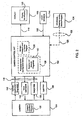
- FIG. 1 is a block diagram in the context of one advantageous embodiment of the present invention shown in Figs. 5 and 6 .
- FIG. 2 is a block diagram of the advantageous embodiment according to FIG. 1 .
- FIG. 3 is a block diagram of the advantageous embodiment according to FIG. 1 .
- FIG. 4 is a block diagram of the advantageous embodiment according to FIG. 1 .
- FIG. 5 is an illustration of the Camera Control Unit according to the advantageous embodiment of FIG. 1 .
- FIG. 6 is an illustration of the Camera Control Unit according to the advantageous embodiment of FIG. 1 .
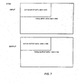
- FIG. 7 is an illustration of input and output dimension for HD project resampling for NTSC.
- FIG. 8 is an illustration of input and output dimension for HD project resampling for PAL.
- FIG. 1 depicts a system 100 comprising a camera 104 for generating image data.
- Camera 104 is connected to camera control unit 102 via a coupling 116.
- the coupling 116 is provided to supply electrical power to camera 104 as well as to transmit data between camera 104 and camera control unit 102.
- Camera control unit 102 is provided with at least two different inputs, including, a High-Definition (HD) Input 108 and a Standard-Definition (SD) Input 110.
- HD High-Definition
- SD Standard-Definition
- SD generally refers to a line count of up to approximately 720 x 480 NTSC and PAL; while HD refers to systems that utilize a higher line count and may include, for example but not limited to, 1280 x 720 progressive or 1920 x 1080 or interlaced, which are only two of the commonly used HD resolutions.
- HD generally refers to a line count of up to approximately 720 x 480 NTSC and PAL; while HD refers to systems that utilize a higher line count and may include, for example but not limited to, 1280 x 720 progressive or 1920 x 1080 or interlaced, which are only two of the commonly used HD resolutions.
- a user will attach the camera to either the HD input 108 or the SD input 110.
- processor / configurable device 128 shown in camera control unit 102. Based on the connected camera, the camera control unit 102 will be configured to function with the connected camera 104 via either the HD input 108 or the SD input 110.
- a display 106 may be connected to camera control unit 102 via a coupling 118. Upon connection, the camera control unit 102 can detect the attached display 106 and determine the correct signal format for proper functioning of display 106. For example, display 106 may be designed to display only SD video signals. That being the case, camera control unit 102 will transmit an SD signal format to display 106 whether an SD or an HD camera is connected. Alternatively, it may be determined that the connected display 106 may be designed to display HD video signals. In this case, if the connected camera 104 is an HD camera, an HD signal is transmitted to display 106.
- an enhanced SD signal may be transmitted to the HD display 106.
- the following signal format types may be used SD input ⁇ SD output ; SD input ⁇ Enhanced SD output ; HD input ⁇ SD output ; and HD input ⁇ HD output .
- categorization of inputs and outputs as SD or HD is not intended to limit the categories to a single signal format, but rather, many differing signal formats may be categorized as SD and many differing signal formats may be categorized as HD.
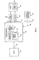
- configuration information for either camera 104 and / or display 106 may be located on camera 104 and display 106 respectively.
- configuration information may be located in storage 126 that may comprise an internal storage device for camera control unit 102 with camera 104 and display 106 providing an identifier for camera control unit 102 to look up the correct configuration information.
- configuration information may be remotely located and may be transmitted to camera control unit 102 via a line 120 over a network connection 122 from a remote storage 124.
- the network connection 122 may include, for example, an Intranet, the Internet and / or the like.
- a camera identifier / program 130 stored on camera 104 may be transmitted as camera information / program(s) 132 to camera control unit 102.
- the camera identifier may comprise discrete data or may comprise a program.
- one or more programs may be stored on camera 104 and transmitted as or with the camera identification data.
- the processor and / or configurable device 128 receives the camera information / program(s) and executes the program(s) 142, which allows the processor and / or configurable device 128 to receive and process image data generated and transmitted by camera 104.
- one or more programs may be located on internal storage 126 or may be located on remote storage 124.
- camera identifier 130 may be transmitted to camera control unit 102.
- a program(s) may be transmitted to processor and / or configurable device 128 from camera 104, internal storage 126 or remote storage 124.
- camera control unit 102 may issue commands 134 to camera 104, for example, to adjust color balance, light, focal distance, resolution, zoom, focus, shading, and other optical characteristics.
- Camera 104 may then generate and transmit image data 136, which is received and processed by camera control unit 102.
- Image data received and processed by camera control unit 102 is then transmitted in the proper signal format to display 106.
- light path 138, 140 and light source 144 may comprise virtually any type of commonly used light source including, for example, a Light Emitting Diode while the light path may comprise, for instance, a coherent or non-coherent fiber optic bundle. While the light path 138, 140 is illustrated passing through camera control unit 102, it is contemplated that the light path may be separate and apart from camera control unit 102. Additionally, it is contemplated that light path 138 may be combined into coupling 116 or light source 144 may be provided in camera 104, or camera control unit 102.
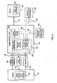
- FIG. 3 illustrates still another advantageous embodiment of the present invention.
- display identifier 146 stored on display 106 is transmitted as display identification 148 to camera control unit 102.
- camera control unit 102 will determine a signal format that will be compatible with display 106.
- Image data 150 will then be transmitted to display 106 in the properly configured signal format.
- camera control unit 102 can retrieve information and / or a program from, for example, internal storage 126, remote storage 124 or even from display 106 for configuration of the output signal for sending image data 150 in the proper format.
- Example 1 For NTSC the specifications in one advantageous embodiment are as follows:
- Total input data active and inactive.
- Total number of input lines 525.
- To find the total number of pixels per line: in 1 second there are 145.2727 x 10 6 pixels. Also, in 1 second there are 60/1.001 frames of (525 x total number of pixels per input line (145.2727 ⁇ 10 6 / ((60/1.001) x 525) 4680.
- Example 2 For PAL the specifications in one advantageous embodiment are as follows:
- Total input data active and inactive.
- Total number of input lines 625.
- To find the total number of pixels per line: in 1 second there are 127.6875 x 10 6 pixels. Also, in 1 second there are 50 frames of (625 x total number of pixels per input line (127.6875 x 10 6 / (50 x 625) 4086.
- NTSC and PAL SD NTSC and PAL
- RGB NTSC and PAL
- Y/C s-video
- Serial Digital Interface (SDI), standardized in ITU-R BT.656 and SMPTE 259M, is a digital video interface used for broadcast-grade video.
- a related standard, known as High Definition Serial Digital Interface (HD-SDI) is standardized in SMPTE 292M and provides a nominal data rate of 1.485 Gbit/s.
- Digital Visual Interface is a video interface standard designed to maximize the visual quality of digital display devices such as flat panel LCD computer displays and digital projectors and is partially compatible with the HDMI standard in digital mode (DVI-D).
- the DVI interface uses a digital protocol in which the desired illumination of pixels is transmitted as binary data. When the display is driven at its native resolution, it will read each number and apply that brightness to the appropriate pixel. In this way, each pixel in the output buffer of the source device corresponds directly to one pixel in the display device.
- HDMI High-Definition Multimedia Interface
- HDMI is an all-digital audio/visual interface capable of transmitting uncompressed streams.
- HDMI is compatible with High-bandwidth Digital Content Protection (HDCP) Digital Rights Management technology.
- HDMI provides an interface between any compatible digital audio/video source and a compatible digital audio and / or video monitor, such as a digital television (DTV).
- DTV digital television
- a storage device for storing the program(s) for configuration of the processor and / or configurable device 128 may reside on camera 104, internal storage 126, a removable storage 154 (e.g. a removable drive or storage medium) or a remote storage 124 (e.g. via a network connection).
- camera control unit 102 can compare program(s) versions from the various storage mediums to determine if the camera identification /program(s) received from camera 104 is the latest version and if not, the camera information can be updated. This can happen automatically, or the system could, for example, prompt the user to decide whether or not to update the camera information.
- certain programs and / or features may become available.
- FIGS. 5 and 6 illustrate the camera control unit 102 per one embodiment of the present invention.
- Camera control unit 102 includes a case 160 having a front panel 162.
- Front panel 162 is provided with multiple inputs including, an HD receptacle 164 and an SD receptacle 166.
- a power switch 168 may also be positioned on front panel 162.
- Also positioned on front panel 162 is slideable door 170 and tracks 172.
- a camera 104 is provided with a plug (not shown) that, based upon the camera configuration (e.g. either HD or SD), is keyed to fit in either HD receptacle 164 or SD receptacle 166.
- the door 170 may simply be slid to cover the receptacle that is not currently in use.
- the door is provided with a protrusion(s) (not shown) that engage with a channel 174 provided in tracks 172 so as to capture door 170 but still allow for lateral sliding action.
- HD receptacle 164 and SD receptacle 166 are not illustrated including an optical connection or coupling, it is contemplated that they may be provided with such.
Landscapes
- Health & Medical Sciences (AREA)
- Life Sciences & Earth Sciences (AREA)
- Surgery (AREA)
- Biomedical Technology (AREA)
- Medical Informatics (AREA)
- Optics & Photonics (AREA)
- Pathology (AREA)
- Radiology & Medical Imaging (AREA)
- Biophysics (AREA)
- Engineering & Computer Science (AREA)
- Physics & Mathematics (AREA)
- Heart & Thoracic Surgery (AREA)
- Nuclear Medicine, Radiotherapy & Molecular Imaging (AREA)
- Molecular Biology (AREA)
- Animal Behavior & Ethology (AREA)
- General Health & Medical Sciences (AREA)
- Public Health (AREA)
- Veterinary Medicine (AREA)
- Studio Devices (AREA)
- Endoscopes (AREA)
Claims (19)
- Videoendoskopisches System (100), das Folgendes aufweist:eine Kamera (104) zum Generieren von Bilddaten;eine Anzeige (106) zum Anzeigen der Bilddaten; undeine Kamerasteuerungseinheit (102), die die Kamera (104) mit der Anzeige koppelt, wobei die Kamerasteuerungseinheit (102) Folgendes aufweist:einen ersten Eingang (108) zum Empfangen von Bilddaten, die ein erstes Signalformat aufweisen, wobei der erste Eingang (108) einen ersten Anschluss (164) aufweist;einen zweiten Eingang (110) zum Empfangen von Bilddaten, die ein zweites Signalformat aufweisen, das sich von dem ersten Signalformat unterscheidet, wobei der zweite Eingang (110) einen zweiten Anschluss (166) aufweist;wobei der erste Eingang (108) hoch aufgelöste (HD) Eingangsbilddaten aufweist, und der zweite Eingang (110) standardaufgelöste (SD) Eingangsbilddaten aufweist,einen Ausgang zum Übertragen der Bilddaten zu der Anzeige (106), wobei die Anzeige (106) über eine Kopplung (108) mit der Kamerasteuerungseinheit (102) verbunden ist,dadurch gekennzeichnet, dasseine Tür (170) derart ausgebildet ist, um selektiv entweder den ersten oder den zweiten Anschluss (164, 166) zu bedecken; undwobei beim Verbinden mit der Anzeige (106) die Kamerasteuerungseinheit (102) ein kompatibles Ausgangssignalformat für die Anzeige (106) basierend auf einem Anzeigenidentifikator ermittelt, der eine bestimmte mit der Kamerasteuerungseinheit (102) gekoppelte Anzeige (106) identifiziert.
- Videoendoskopiesystem gemäß Anspruch 1, wobei der erste Anschluss (164) dafür ausgebildet ist, um einen ersten Stecker aufzunehmen, und der zweite Anschluss (166) dafür ausgebildet ist, um einen zweiten Stecker aufzunehmen, wobei der erste und zweite Stecker unterschiedliche Ausgestaltungen haben.
- Videoendoskopiesystem gemäß einem der vorherigen Ansprüche, wobei die Tür (170) derart verschiebbar ist, dass, wenn die Tür (170) den ersten Anschluss (166) bedeckt, der zweite Anschluss (168) exponiert ist; und wenn die Tür (170) den zweiten Anschluss (168) bedeckt, der erste Anschluss (166) exponiert ist.
- Videoendoskopiesystem gemäß Anspruch 3, das ferner eine Schiene (172) aufweist, die mit der verschiebbaren Tür (170) im Eingriff steht, wobei die verschiebbare Tür einen Vorsprung aufweist, der mit einer Ausnehmung in der Schiene (172) im Eingriff steht.
- Videoendoskopiesystem nach Anspruch 4, wobei die Schiene (172) zumindest zwei Schienen aufweist, wobei jede Schiene eine Ausnehmung aufweist, und die verschiebbare Tür (170) zumindest zwei Vorsprünge aufweist, die mit den Ausnehmungen im Eingriff stehen.
- Videoendoskopiesystem gemäß einem der vorherigen Ansprüche, wobei das Ausgangssignalformat ausgewählt ist aus der Gruppe bestehend aus: NTSC, PAL, Serielle Digitale Schnittstelle (SDI), Hochauflösende Serielle Digitale Schnittstelle (HD-SDI), Digitale Visuelle Schnittstelle (DVI), Hochauflösende Multimedia Schnittstelle (HDMI) und Kombinationen hiervon.
- Videoendoskopiesystem gemäß einem der vorherigen Ansprüche, wobei bei Verbindung der Kamera (103) mit der Kamerasteuerungseinheit (102) ein Kameraidentifikator und ein Programm an die Kamerasteuerungseinheit (102) derart übertragen werden, dass die Kamerasteuerungseinheit (102) sich selbst konfiguriert, um mit der Kamera (104) kompatibel zu sein.
- Videoendoskospiesystem nach Anspruch 7, wobei die Kamerasteuerungseinheit (102) ferner einen Mikroprozessor (128), um das Programm zu empfangen und auszuführen, und ein konfigurierbares Teil, um die Bilddaten zu empfangen, aufweist.
- Videoendoskopiesystem nach Anspruch 8, wobei der Mikroprozessor das empfangene Programm mit einer zweiten Version des Programmes vergleicht, um zu ermitteln, ob das empfangene Programm die aktuellste Version ist, und wenn dies nicht der Fall ist, die Kamera (104) mit der aktuellen Version des Programmes aktualisiert wird.
- Videoendoskopiesystem nach Anspruch 9, wobei die zweite Version des Programmes über den Mikroprozessor (128) zugänglich ist, und zwar über: einen internen Speicher (126), einen Wechselspeicher (154) und/oder eine Netzwerkverbindung zu einem entfernten Speicher (124).
- Videoendoskopiesystem gemäß einem der Ansprüche 8 bis 10, wobei die Kamera (104) ein Prozessorprogramm zur Programmierung des Mikroprozessors (128) und ein Vorrichtungsprogramm zur Programmierung des konfigurierbaren Teils überträgt.
- Videoendoskopiesystem gemäß einem der Ansprüche 8 bis 11, wobei das konfigurierbare Teil ausgewählt ist aus der Gruppe bestehend aus: einem feldprogrammierbaren Gate-Array, einem Mikroprozessor, einem digitalen Signalprozessor und Kombinationen hiervon.
- Videoendoskopiesystem gemäß einem der vorherigen Ansprüche, wobei die Kamera (104) über einen Kopplungsmechanismus mit einem Endoskop gekoppelt ist.
- Videoendoskopiesystem gemäß Anspruch 13, das ferner einen Beleuchtungskanal aufweist, der mit dem Endoskop gekoppelt ist, wobei der Beleuchtungskanal ein erhellendes Licht von einer Lichtquelle zu dem Endoskop führt.
- Verfahren zum Übertragen von Bilddaten von mehreren Kameras (104) mit unterschiedlichen Signalformaten an eine Kamerasteuerungseinheit (102) und eine Anzeige (106) über eine Kamerasteuerung, das folgende Schritte aufweist:Bereitstellung eines ersten Anschlusses (164) und eines zweiten Anschlusses (166) in der Kamerasteuerungseinheit (102), wobei der erste Anschluss (164) eine erste Ausgestaltung aufweist, und der zweite Anschluss (166) eine zweite Ausgestaltung aufweist, die sich von der ersten Ausgestaltung unterscheidet;Bereitstellung einer Kamera (104), die entweder die erste Steckerausgestaltung oder die zweite Steckerausgestaltung aufweist, die eine Kopplung zu den Ausgestaltungen des ersten bzw. zweiten Anschlusses (164, 166) schafft;Koppeln der Kamera (104) entweder mit dem ersten oder mit dem zweiten Anschluss (164, 166);Empfangen eines Kameraidentifikators und eines Programms;Konfigurieren der Kamerasteuerungseinheit (102) basierend auf dem Kameraidentifikator und dem empfangenen Programm;Koppeln der Kamerasteuerungseinheit (102) mit der Anzeige (104) über eine Verbindung (108);Übertragen der Bilddaten an die Anzeige (106); undAnzeigen der Bilddaten auf der Anzeige (106),wobei der erste Eingang ein Eingang für hochaufgelöste (HD) Bilddaten ist, und wobei der zweite Eingang ein Eingang für standardaufgelöste (SD) Bilddaten ist, gekennzeichnet durchselektives Bedecken von entweder dem ersten oder zweiten Anschluss (164, 166) mit einer verschiebbaren Tür (170);Empfangen eines Anzeigeidentifikators; undKonfigurieren eines Ausgangssignals, um mit der verbundenen Anzeige (106) kompatibel zu sein.
- Verfahren gemäß Anspruch 15, das ferner die Schritte des Skalierens der Bilddaten, die von der Kamera (104) empfangen werden, in ein skaliertes Größenformat aufweist, das mit dem identifizierten Display (106) kompatibel ist.
- Verfahren nach Anspruch 16, wobei, wenn die identifizierte Anzeige (106) mit NTSC kompatibel ist, die HD-Bilddaten gemäß einem ersten Vorgang skaliert werden, und, wenn die Anzeige (106) mit PAL kompatibel ist, die SD-Bilddaten gemäß einem zweiten Vorgang skaliert werden, der sich von dem ersten Vorgang unterscheidet.
- Verfahren gemäß einem der Ansprüche 15 bis 17, wobei das Programm von der Kamera (104) empfangen und in letzterer gespeichert wird.
- Verfahren gemäß Anspruch 18, wobei die Kamerasteuerungseinheit (102) das von der Kamera (104) empfangene Programm mit einer anderen Version des Programms vergleicht, um zu ermitteln, ob das empfangene Programm die aktuellste Version ist, und sollte dies nicht der Fall sein, die Kamera (104) mit der aktuellen Version des Programms aktualisiert wird.
Priority Applications (1)
| Application Number | Priority Date | Filing Date | Title |
|---|---|---|---|
| EP13175797.3A EP2649927A3 (de) | 2007-04-03 | 2008-03-29 | Universal-Kamerasteuereinheit |
Applications Claiming Priority (1)
| Application Number | Priority Date | Filing Date | Title |
|---|---|---|---|
| US11/695,960 US8810637B2 (en) | 2007-04-03 | 2007-04-03 | Universal camera control unit |
Related Child Applications (2)
| Application Number | Title | Priority Date | Filing Date |
|---|---|---|---|
| EP13175797.3A Division EP2649927A3 (de) | 2007-04-03 | 2008-03-29 | Universal-Kamerasteuereinheit |
| EP13175797.3 Division-Into | 2013-07-09 |
Publications (3)
| Publication Number | Publication Date |
|---|---|
| EP1977682A2 EP1977682A2 (de) | 2008-10-08 |
| EP1977682A3 EP1977682A3 (de) | 2008-12-17 |
| EP1977682B1 true EP1977682B1 (de) | 2013-12-25 |
Family
ID=39638858
Family Applications (2)
| Application Number | Title | Priority Date | Filing Date |
|---|---|---|---|
| EP08006213.6A Ceased EP1977682B1 (de) | 2007-04-03 | 2008-03-29 | Universal-Kamerasteuereinheit |
| EP13175797.3A Withdrawn EP2649927A3 (de) | 2007-04-03 | 2008-03-29 | Universal-Kamerasteuereinheit |
Family Applications After (1)
| Application Number | Title | Priority Date | Filing Date |
|---|---|---|---|
| EP13175797.3A Withdrawn EP2649927A3 (de) | 2007-04-03 | 2008-03-29 | Universal-Kamerasteuereinheit |
Country Status (4)
| Country | Link |
|---|---|
| US (1) | US8810637B2 (de) |
| EP (2) | EP1977682B1 (de) |
| JP (1) | JP4890489B2 (de) |
| CA (1) | CA2618510C (de) |
Families Citing this family (42)
| Publication number | Priority date | Publication date | Assignee | Title |
|---|---|---|---|---|
| US8633975B2 (en) | 2008-01-16 | 2014-01-21 | Karl Storz Imaging, Inc. | Network based endoscopic surgical system |
| US9526407B2 (en) * | 2008-04-25 | 2016-12-27 | Karl Storz Imaging, Inc. | Wirelessly powered medical devices and instruments |
| US9603512B2 (en) | 2008-04-25 | 2017-03-28 | Karl Storz Imaging, Inc. | Wirelessly powered medical devices and instruments |
| US9872609B2 (en) | 2009-06-18 | 2018-01-23 | Endochoice Innovation Center Ltd. | Multi-camera endoscope |
| US9492063B2 (en) | 2009-06-18 | 2016-11-15 | Endochoice Innovation Center Ltd. | Multi-viewing element endoscope |
| EP2865322B1 (de) | 2009-06-18 | 2020-07-22 | EndoChoice, Inc. | Mehrkamera-Endoskop |
| US11864734B2 (en) | 2009-06-18 | 2024-01-09 | Endochoice, Inc. | Multi-camera endoscope |
| US10165929B2 (en) | 2009-06-18 | 2019-01-01 | Endochoice, Inc. | Compact multi-viewing element endoscope system |
| US9713417B2 (en) | 2009-06-18 | 2017-07-25 | Endochoice, Inc. | Image capture assembly for use in a multi-viewing elements endoscope |
| WO2012077116A1 (en) | 2010-12-09 | 2012-06-14 | Peermedical Ltd. | Flexible electronic circuit board for a multi-camera endoscope |
| US9706903B2 (en) | 2009-06-18 | 2017-07-18 | Endochoice, Inc. | Multiple viewing elements endoscope system with modular imaging units |
| US9101287B2 (en) | 2011-03-07 | 2015-08-11 | Endochoice Innovation Center Ltd. | Multi camera endoscope assembly having multiple working channels |
| US11547275B2 (en) | 2009-06-18 | 2023-01-10 | Endochoice, Inc. | Compact multi-viewing element endoscope system |
| US9642513B2 (en) | 2009-06-18 | 2017-05-09 | Endochoice Inc. | Compact multi-viewing element endoscope system |
| US12137873B2 (en) | 2009-06-18 | 2024-11-12 | Endochoice, Inc. | Compact multi-viewing element endoscope system |
| US9101268B2 (en) | 2009-06-18 | 2015-08-11 | Endochoice Innovation Center Ltd. | Multi-camera endoscope |
| US9901244B2 (en) | 2009-06-18 | 2018-02-27 | Endochoice, Inc. | Circuit board assembly of a multiple viewing elements endoscope |
| US8926502B2 (en) | 2011-03-07 | 2015-01-06 | Endochoice, Inc. | Multi camera endoscope having a side service channel |
| US11278190B2 (en) | 2009-06-18 | 2022-03-22 | Endochoice, Inc. | Multi-viewing element endoscope |
| US9402533B2 (en) | 2011-03-07 | 2016-08-02 | Endochoice Innovation Center Ltd. | Endoscope circuit board assembly |
| US12220105B2 (en) | 2010-06-16 | 2025-02-11 | Endochoice, Inc. | Circuit board assembly of a multiple viewing elements endoscope |
| US9560953B2 (en) | 2010-09-20 | 2017-02-07 | Endochoice, Inc. | Operational interface in a multi-viewing element endoscope |
| EP4233680B1 (de) | 2010-09-20 | 2025-06-18 | EndoChoice, Inc. | Distaler endoskopabschnitt umfassend eine einheitliche flüssigkeitskanal-komponente |
| EP2635932B1 (de) | 2010-10-28 | 2019-06-05 | EndoChoice Innovation Center Ltd. | Optische systeme für multi-sensor-endoskope |
| US12204087B2 (en) | 2010-10-28 | 2025-01-21 | Endochoice, Inc. | Optical systems for multi-sensor endoscopes |
| US9320419B2 (en) | 2010-12-09 | 2016-04-26 | Endochoice Innovation Center Ltd. | Fluid channeling component of a multi-camera endoscope |
| US11889986B2 (en) | 2010-12-09 | 2024-02-06 | Endochoice, Inc. | Flexible electronic circuit board for a multi-camera endoscope |
| US9101266B2 (en) | 2011-02-07 | 2015-08-11 | Endochoice Innovation Center Ltd. | Multi-element cover for a multi-camera endoscope |
| CA2798729A1 (en) | 2011-12-13 | 2013-06-13 | Peermedical Ltd. | Rotatable connector for an endoscope |
| EP2604175B1 (de) | 2011-12-13 | 2019-11-20 | EndoChoice Innovation Center Ltd. | Endoskop mit entfernbarer Spitze |
| US9560954B2 (en) | 2012-07-24 | 2017-02-07 | Endochoice, Inc. | Connector for use with endoscope |
| US20140142383A1 (en) * | 2012-11-22 | 2014-05-22 | Gyrus Acmi, Inc. (D.B.A. Olympus Surgical Technologies America) | Endoscope Camera Head Memory |
| US9319636B2 (en) * | 2012-12-31 | 2016-04-19 | Karl Storz Imaging, Inc. | Video imaging system with multiple camera white balance capability |
| US20140327751A1 (en) * | 2012-12-31 | 2014-11-06 | Timothy King | High definition (hd) inter-module link interface |
| US9841280B2 (en) | 2012-12-31 | 2017-12-12 | Karl Storz Imaging, Inc. | Modular medical imaging system |
| US9993142B2 (en) | 2013-03-28 | 2018-06-12 | Endochoice, Inc. | Fluid distribution device for a multiple viewing elements endoscope |
| US9986899B2 (en) | 2013-03-28 | 2018-06-05 | Endochoice, Inc. | Manifold for a multiple viewing elements endoscope |
| JP6178099B2 (ja) * | 2013-04-05 | 2017-08-09 | ソニー株式会社 | 中間ユニットおよびカメラシステム |
| US8974472B2 (en) | 2013-04-16 | 2015-03-10 | Calcula Technologies, Inc. | Method for removing kidney stones |
| US10188411B2 (en) | 2013-04-16 | 2019-01-29 | Calcula Technologies, Inc. | Everting balloon for medical devices |
| US10219864B2 (en) | 2013-04-16 | 2019-03-05 | Calcula Technologies, Inc. | Basket and everting balloon with simplified design and control |
| US10499794B2 (en) | 2013-05-09 | 2019-12-10 | Endochoice, Inc. | Operational interface in a multi-viewing element endoscope |
Family Cites Families (45)
| Publication number | Priority date | Publication date | Assignee | Title |
|---|---|---|---|---|
| JPS61175868A (ja) | 1985-01-31 | 1986-08-07 | Mitsubishi Electric Corp | 指紋判別装置 |
| JPS62140564A (ja) * | 1985-12-13 | 1987-06-24 | Olympus Optical Co Ltd | 電子内視鏡装置 |
| JPS62213073A (ja) | 1986-03-14 | 1987-09-18 | 東芝ライテック株式会社 | 配線器具 |
| JPH03156691A (ja) | 1989-11-15 | 1991-07-04 | Fujitsu Ltd | 指紋読取り用指ガイド |
| JP3382973B2 (ja) * | 1992-02-07 | 2003-03-04 | オリンパス光学工業株式会社 | 電子内視鏡装置 |
| US5347991A (en) * | 1992-10-20 | 1994-09-20 | Nakao Naomi L | Endoscope suction trap and associated method |
| CA2159597C (en) * | 1993-03-31 | 2005-05-17 | Philip J. Branson | Managing information in an endoscopy system |
| US5589874A (en) * | 1993-06-09 | 1996-12-31 | Origin Medsystems, Inc. | Video imaging system with external area processing optimized for small-diameter endoscopes |
| JPH10269344A (ja) | 1997-03-27 | 1998-10-09 | Sony Corp | 指紋読み取り装置 |
| US6982742B2 (en) * | 1997-10-06 | 2006-01-03 | Adair Edwin L | Hand-held computers incorporating reduced area imaging devices |
| ES2137879B1 (es) * | 1997-12-02 | 2000-08-16 | Francisco Soria Melguizo S A | Sistema analizador de imagenes producidas por reacciones bacterianas. |
| ATE418126T1 (de) | 1998-04-07 | 2009-01-15 | Gerald R Black | Identifizierungsbestätigungssystem |
| JP3950589B2 (ja) * | 1998-08-28 | 2007-08-01 | キヤノン株式会社 | 情報処理装置、プログラム更新方法および記憶媒体 |
| US6768774B1 (en) * | 1998-11-09 | 2004-07-27 | Broadcom Corporation | Video and graphics system with video scaling |
| JP3915298B2 (ja) | 1999-01-26 | 2007-05-16 | カシオ計算機株式会社 | 電子機器 |
| JP4042080B2 (ja) | 1999-02-25 | 2008-02-06 | ソニー株式会社 | 編集装置 |
| JP3561485B2 (ja) * | 2000-08-18 | 2004-09-02 | 株式会社メディアグルー | 符号化信号分離・合成装置、差分符号化信号生成装置、符号化信号分離・合成方法、差分符号化信号生成方法、符号化信号分離・合成プログラムを記録した媒体および差分符号化信号生成プログラムを記録した媒体 |
| US6471649B1 (en) * | 2000-11-09 | 2002-10-29 | Koninklijke Philips Electronics N.V. | Method and apparatus for storing image information in an ultrasound device |
| JP2002199291A (ja) | 2000-12-27 | 2002-07-12 | Olympus Optical Co Ltd | 撮像装置 |
| JP3961765B2 (ja) * | 2000-12-28 | 2007-08-22 | ペンタックス株式会社 | 電子内視鏡システム |
| KR100400542B1 (ko) * | 2001-02-28 | 2003-10-08 | 엘지전자 주식회사 | 디지털 방송 수신장치의 광고를 이용한 시스템 소프트웨어업그레이드 장치 및 방법 |
| US7349098B2 (en) * | 2001-05-07 | 2008-03-25 | University Of Washington | Simultaneous beam-focus and coherence-gate tracking for real-time optical coherence tomography |
| JP2003058872A (ja) | 2001-08-21 | 2003-02-28 | Sony Corp | 指紋検出装置、その製造方法及び成膜装置 |
| US8274559B2 (en) * | 2001-11-09 | 2012-09-25 | Karl Storz Imaging, Inc. | Replaceable hardware component of a camera control unit for video systems |
| US20030147004A1 (en) * | 2002-02-07 | 2003-08-07 | Tongt-Huei Wang | Power supply lock for use with a digital camera having a connector door to slidably and selectively close/open a power supply recess |
| JP2004006189A (ja) | 2002-05-31 | 2004-01-08 | Hitachi Hybrid Network Co Ltd | 電源アダプタ |
| WO2004025963A1 (en) * | 2002-09-13 | 2004-03-25 | Karl Storz Imaging, Inc. | Video recording and image capture device |
| US20040095507A1 (en) * | 2002-11-18 | 2004-05-20 | Medicapture, Inc. | Apparatus and method for capturing, processing and storing still images captured inline from an analog video stream and storing in a digital format on removable non-volatile memory |
| JP2004312468A (ja) | 2003-04-08 | 2004-11-04 | Olympus Corp | 映像切換装置及び映像システム |
| JP2004344555A (ja) | 2003-05-26 | 2004-12-09 | Olympus Corp | 医療用画像記録装置 |
| KR100677303B1 (ko) * | 2003-12-26 | 2007-02-05 | 엘지전자 주식회사 | 휴대 단말기 |
| EP1699230B1 (de) * | 2004-01-23 | 2009-03-18 | Sony Corporation | Drehenscharnier-mechanismus und vorrichtung zur bildaufnahme |
| JP4458925B2 (ja) * | 2004-05-14 | 2010-04-28 | キヤノン株式会社 | 映像処理装置 |
| US7570301B2 (en) * | 2004-06-03 | 2009-08-04 | Electronic Security Products, Inc. | Device, system and method of mounting audio/video capturing equipment |
| US7855727B2 (en) * | 2004-09-15 | 2010-12-21 | Gyrus Acmi, Inc. | Endoscopy device supporting multiple input devices |
| AU2005291952A1 (en) * | 2004-09-30 | 2006-04-13 | Boston Scientific Limited | Adapter for use with digital imaging medical device |
| US8872906B2 (en) * | 2005-01-05 | 2014-10-28 | Avantis Medical Systems, Inc. | Endoscope assembly with a polarizing filter |
| US8289381B2 (en) * | 2005-01-05 | 2012-10-16 | Avantis Medical Systems, Inc. | Endoscope with an imaging catheter assembly and method of configuring an endoscope |
| GB2425424B (en) | 2005-04-22 | 2010-09-29 | Single Use Surgical Ltd | Disposable flexible endoscope |
| US7834867B2 (en) * | 2006-04-11 | 2010-11-16 | Microvision, Inc. | Integrated photonics module and devices using integrated photonics modules |
| KR100761480B1 (ko) * | 2006-05-26 | 2007-09-27 | 삼성전자주식회사 | 휴대용 전자기기 및 카메라 |
| US20090231419A1 (en) * | 2007-02-06 | 2009-09-17 | Avantis Medical Systems, Inc. | Endoscope Assembly and Method of Performing a Medical Procedure |
| US20090085897A1 (en) * | 2007-09-28 | 2009-04-02 | Olympus Medical Systems Corp. | Image display apparatus |
| US7751185B2 (en) * | 2008-09-16 | 2010-07-06 | Amtek System Co., Ltd. | Docking station applied to a portable electronic device |
| US8325224B2 (en) * | 2009-12-25 | 2012-12-04 | Kabushiki Kaisha Toshiba | Head separation camera apparatus |
-
2007
- 2007-04-03 US US11/695,960 patent/US8810637B2/en active Active
-
2008
- 2008-01-24 CA CA2618510A patent/CA2618510C/en active Active
- 2008-03-25 JP JP2008079307A patent/JP4890489B2/ja not_active Expired - Fee Related
- 2008-03-29 EP EP08006213.6A patent/EP1977682B1/de not_active Ceased
- 2008-03-29 EP EP13175797.3A patent/EP2649927A3/de not_active Withdrawn
Also Published As
| Publication number | Publication date |
|---|---|
| JP4890489B2 (ja) | 2012-03-07 |
| JP2008259196A (ja) | 2008-10-23 |
| US20080246838A1 (en) | 2008-10-09 |
| EP2649927A3 (de) | 2013-11-27 |
| EP2649927A8 (de) | 2014-07-09 |
| CA2618510A1 (en) | 2008-10-03 |
| US8810637B2 (en) | 2014-08-19 |
| EP1977682A3 (de) | 2008-12-17 |
| EP2649927A2 (de) | 2013-10-16 |
| CA2618510C (en) | 2013-12-31 |
| EP1977682A2 (de) | 2008-10-08 |
Similar Documents
| Publication | Publication Date | Title |
|---|---|---|
| EP1977682B1 (de) | Universal-Kamerasteuereinheit | |
| US11118905B2 (en) | Modular medical imaging system | |
| US20140320684A1 (en) | Universal Control Unit and Display With Non-Contact Adjustment Functionality | |
| CA2679638C (en) | Image capture module | |
| US10104331B2 (en) | Camera control unit with stereoscopic video recording and archive | |
| US20140327751A1 (en) | High definition (hd) inter-module link interface | |
| US20120200683A1 (en) | System for recording and reproducing images | |
| JP4800562B2 (ja) | ビデオ撮像システム及びビデオ撮像方法 | |
| US20100145146A1 (en) | Endoscopic digital recording system with removable screen and storage device | |
| CN109310408B (zh) | 具有与不同的视频数据信号源连接的多个连接接口的内窥镜系统 | |
| US20200288947A1 (en) | Reprogrammable Video Imaging System with Modular Architecture | |
| US9912911B2 (en) | Inter-module link interface | |
| EP2749203B1 (de) | Einzelschalter für modulares medizinisches Bildgebungssystem | |
| CN205179246U (zh) | 医疗多功能存储主机 | |
| US20090189907A1 (en) | Medical support control system | |
| SCHWAITZBERG | MELS Imaging Systems in Minimally Invasive Surgery |
Legal Events
| Date | Code | Title | Description |
|---|---|---|---|
| PUAI | Public reference made under article 153(3) epc to a published international application that has entered the european phase |
Free format text: ORIGINAL CODE: 0009012 |
|
| 17P | Request for examination filed |
Effective date: 20080329 |
|
| AK | Designated contracting states |
Kind code of ref document: A2 Designated state(s): AT BE BG CH CY CZ DE DK EE ES FI FR GB GR HR HU IE IS IT LI LT LU LV MC MT NL NO PL PT RO SE SI SK TR |
|
| AX | Request for extension of the european patent |
Extension state: AL BA MK RS |
|
| PUAL | Search report despatched |
Free format text: ORIGINAL CODE: 0009013 |
|
| AK | Designated contracting states |
Kind code of ref document: A3 Designated state(s): AT BE BG CH CY CZ DE DK EE ES FI FR GB GR HR HU IE IS IT LI LT LU LV MC MT NL NO PL PT RO SE SI SK TR |
|
| AX | Request for extension of the european patent |
Extension state: AL BA MK RS |
|
| AKX | Designation fees paid |
Designated state(s): DE FR GB IT |
|
| 17Q | First examination report despatched |
Effective date: 20110629 |
|
| REG | Reference to a national code |
Ref country code: DE Ref legal event code: R079 Ref document number: 602008029477 Country of ref document: DE Free format text: PREVIOUS MAIN CLASS: A61B0001045000 Ipc: A61B0001000000 |
|
| GRAP | Despatch of communication of intention to grant a patent |
Free format text: ORIGINAL CODE: EPIDOSNIGR1 |
|
| RIC1 | Information provided on ipc code assigned before grant |
Ipc: A61B 1/00 20060101AFI20130627BHEP Ipc: A61B 1/045 20060101ALI20130627BHEP |
|
| INTG | Intention to grant announced |
Effective date: 20130717 |
|
| RAP1 | Party data changed (applicant data changed or rights of an application transferred) |
Owner name: KARL STORZ IMAGING, INC. |
|
| GRAS | Grant fee paid |
Free format text: ORIGINAL CODE: EPIDOSNIGR3 |
|
| GRAA | (expected) grant |
Free format text: ORIGINAL CODE: 0009210 |
|
| AK | Designated contracting states |
Kind code of ref document: B1 Designated state(s): DE FR GB IT |
|
| REG | Reference to a national code |
Ref country code: GB Ref legal event code: FG4D |
|
| REG | Reference to a national code |
Ref country code: DE Ref legal event code: R096 Ref document number: 602008029477 Country of ref document: DE Effective date: 20140213 |
|
| REG | Reference to a national code |
Ref country code: DE Ref legal event code: R097 Ref document number: 602008029477 Country of ref document: DE |
|
| PLBE | No opposition filed within time limit |
Free format text: ORIGINAL CODE: 0009261 |
|
| STAA | Information on the status of an ep patent application or granted ep patent |
Free format text: STATUS: NO OPPOSITION FILED WITHIN TIME LIMIT |
|
| 26N | No opposition filed |
Effective date: 20140926 |
|
| REG | Reference to a national code |
Ref country code: DE Ref legal event code: R097 Ref document number: 602008029477 Country of ref document: DE Effective date: 20140926 |
|
| REG | Reference to a national code |
Ref country code: FR Ref legal event code: PLFP Year of fee payment: 9 |
|
| REG | Reference to a national code |
Ref country code: FR Ref legal event code: PLFP Year of fee payment: 10 |
|
| REG | Reference to a national code |
Ref country code: FR Ref legal event code: PLFP Year of fee payment: 11 |
|
| PGFP | Annual fee paid to national office [announced via postgrant information from national office to epo] |
Ref country code: FR Payment date: 20230222 Year of fee payment: 16 |
|
| PGFP | Annual fee paid to national office [announced via postgrant information from national office to epo] |
Ref country code: IT Payment date: 20230221 Year of fee payment: 16 Ref country code: GB Payment date: 20230222 Year of fee payment: 16 |
|
| P01 | Opt-out of the competence of the unified patent court (upc) registered |
Effective date: 20230527 |
|
| PGFP | Annual fee paid to national office [announced via postgrant information from national office to epo] |
Ref country code: DE Payment date: 20240328 Year of fee payment: 17 |
|
| GBPC | Gb: european patent ceased through non-payment of renewal fee |
Effective date: 20240329 |
|
| PG25 | Lapsed in a contracting state [announced via postgrant information from national office to epo] |
Ref country code: GB Free format text: LAPSE BECAUSE OF NON-PAYMENT OF DUE FEES Effective date: 20240329 |
|
| PG25 | Lapsed in a contracting state [announced via postgrant information from national office to epo] |
Ref country code: FR Free format text: LAPSE BECAUSE OF NON-PAYMENT OF DUE FEES Effective date: 20240331 |
|
| PG25 | Lapsed in a contracting state [announced via postgrant information from national office to epo] |
Ref country code: GB Free format text: LAPSE BECAUSE OF NON-PAYMENT OF DUE FEES Effective date: 20240329 Ref country code: FR Free format text: LAPSE BECAUSE OF NON-PAYMENT OF DUE FEES Effective date: 20240331 |
|
| PG25 | Lapsed in a contracting state [announced via postgrant information from national office to epo] |
Ref country code: IT Free format text: LAPSE BECAUSE OF NON-PAYMENT OF DUE FEES Effective date: 20240329 |
|
| REG | Reference to a national code |
Ref country code: DE Ref legal event code: R119 Ref document number: 602008029477 Country of ref document: DE |
|
| PG25 | Lapsed in a contracting state [announced via postgrant information from national office to epo] |
Ref country code: DE Free format text: LAPSE BECAUSE OF NON-PAYMENT OF DUE FEES Effective date: 20251001 |