EP1976783B1 - Dispenser package - Google Patents
Dispenser package Download PDFInfo
- Publication number
- EP1976783B1 EP1976783B1 EP07762822.0A EP07762822A EP1976783B1 EP 1976783 B1 EP1976783 B1 EP 1976783B1 EP 07762822 A EP07762822 A EP 07762822A EP 1976783 B1 EP1976783 B1 EP 1976783B1
- Authority
- EP
- European Patent Office
- Prior art keywords
- sheets
- stacks
- carrier member
- package
- slot
- Prior art date
- Legal status (The legal status is an assumption and is not a legal conclusion. Google has not performed a legal analysis and makes no representation as to the accuracy of the status listed.)
- Not-in-force
Links
- 239000000853 adhesive Substances 0.000 claims description 24
- 230000001070 adhesive effect Effects 0.000 claims description 24
- 239000000463 material Substances 0.000 claims description 19
- 239000004820 Pressure-sensitive adhesive Substances 0.000 claims description 11
- 238000000576 coating method Methods 0.000 claims description 6
- 239000000758 substrate Substances 0.000 claims description 4
- 239000011248 coating agent Substances 0.000 claims description 3
- 238000010276 construction Methods 0.000 description 8
- 238000000034 method Methods 0.000 description 3
- 239000003086 colorant Substances 0.000 description 2
- 239000002991 molded plastic Substances 0.000 description 2
- 229920000728 polyester Polymers 0.000 description 2
- 229920002799 BoPET Polymers 0.000 description 1
- 230000006978 adaptation Effects 0.000 description 1
- 230000001427 coherent effect Effects 0.000 description 1
- 230000007812 deficiency Effects 0.000 description 1
- 239000012858 resilient material Substances 0.000 description 1
- 229910052709 silver Inorganic materials 0.000 description 1
- 239000004332 silver Substances 0.000 description 1
- -1 sizes Substances 0.000 description 1
- 239000002904 solvent Substances 0.000 description 1
- XLYOFNOQVPJJNP-UHFFFAOYSA-N water Substances O XLYOFNOQVPJJNP-UHFFFAOYSA-N 0.000 description 1
Images

Classifications
-
- B—PERFORMING OPERATIONS; TRANSPORTING
- B65—CONVEYING; PACKING; STORING; HANDLING THIN OR FILAMENTARY MATERIAL
- B65H—HANDLING THIN OR FILAMENTARY MATERIAL, e.g. SHEETS, WEBS, CABLES
- B65H1/00—Supports or magazines for piles from which articles are to be separated
- B65H1/04—Supports or magazines for piles from which articles are to be separated adapted to support articles substantially horizontally, e.g. for separation from top of pile
-
- B—PERFORMING OPERATIONS; TRANSPORTING
- B42—BOOKBINDING; ALBUMS; FILES; SPECIAL PRINTED MATTER
- B42D—BOOKS; BOOK COVERS; LOOSE LEAVES; PRINTED MATTER CHARACTERISED BY IDENTIFICATION OR SECURITY FEATURES; PRINTED MATTER OF SPECIAL FORMAT OR STYLE NOT OTHERWISE PROVIDED FOR; DEVICES FOR USE THEREWITH AND NOT OTHERWISE PROVIDED FOR; MOVABLE-STRIP WRITING OR READING APPARATUS
- B42D5/00—Sheets united without binding to form pads or blocks
- B42D5/003—Note-pads
- B42D5/005—Supports for note-pads
-
- B—PERFORMING OPERATIONS; TRANSPORTING
- B42—BOOKBINDING; ALBUMS; FILES; SPECIAL PRINTED MATTER
- B42D—BOOKS; BOOK COVERS; LOOSE LEAVES; PRINTED MATTER CHARACTERISED BY IDENTIFICATION OR SECURITY FEATURES; PRINTED MATTER OF SPECIAL FORMAT OR STYLE NOT OTHERWISE PROVIDED FOR; DEVICES FOR USE THEREWITH AND NOT OTHERWISE PROVIDED FOR; MOVABLE-STRIP WRITING OR READING APPARATUS
- B42D5/00—Sheets united without binding to form pads or blocks
-
- B—PERFORMING OPERATIONS; TRANSPORTING
- B65—CONVEYING; PACKING; STORING; HANDLING THIN OR FILAMENTARY MATERIAL
- B65D—CONTAINERS FOR STORAGE OR TRANSPORT OF ARTICLES OR MATERIALS, e.g. BAGS, BARRELS, BOTTLES, BOXES, CANS, CARTONS, CRATES, DRUMS, JARS, TANKS, HOPPERS, FORWARDING CONTAINERS; ACCESSORIES, CLOSURES, OR FITTINGS THEREFOR; PACKAGING ELEMENTS; PACKAGES
- B65D83/00—Containers or packages with special means for dispensing contents
- B65D83/08—Containers or packages with special means for dispensing contents for dispensing thin flat articles in succession
- B65D83/0805—Containers or packages with special means for dispensing contents for dispensing thin flat articles in succession through an aperture in a wall
-
- B—PERFORMING OPERATIONS; TRANSPORTING
- B65—CONVEYING; PACKING; STORING; HANDLING THIN OR FILAMENTARY MATERIAL
- B65H—HANDLING THIN OR FILAMENTARY MATERIAL, e.g. SHEETS, WEBS, CABLES
- B65H1/00—Supports or magazines for piles from which articles are to be separated
Definitions
- the present invention relates to dispensers for supplying sheets of material, such as tape flags and/or paper notes, from coherent stacks of such sheets.
- the invention is particularly related to such dispensers that hold and supply sheets from a plurality of stacks of flexible sheets.
- some sheets are made of paper, while other sheets are made of a polymeric material; some sheets are opaque, so as to allow the user to write a message on the sheet, while other sheets are substantially transparent to allow easy viewing of the document to which the sheet is attached; and some sheets have a large percentage of the surface coated with adhesive, while other sheets have only a small percentage of the surface coated with adhesive.
- dispensers because the dispensing characteristics of the sheets also vary with, for example, sheet size or shape, type of sheet material, amount and location of adhesive on the sheet, and so on.
- the dispensers are typically optimized for dispensing a particular type of sheet (for example, polymeric sheets having a majority of one surface coated with adhesive, or paper sheets having only a narrow strip of adhesive on one surface).
- Dispensers tend to be either (1) of the type in which the bottom sheet of the stack of sheets is attached to the bottom of the housing or the stack is otherwise restricted from significant movement in the housing, and the sheets are dispensed through a fairly wide slot as is taught in U.S. Pat. No.
- a user may desire or have need to use sheets of more than one type (e.g., sheets of different colors, sizes, and/or materials). Accordingly, dispensers for use with multiple stacks of sheets are known.
- multi-stack dispensers have deficiencies. For example, multi-stack dispensers using a "shuttling" action to dispense individual sheets are segmented into multiple slots or compartments with each slot or compartment containing a single stack of sheets to allow independent movement and maintain lateral spacing of the stacks.
- Such dispensers are complex to form and do not lend themselves well to automated assembly.
- multi-stack dispensers are typically designed for stacks having sheets with a common construction (e.g., the same sheet material, amounts of adhesive, sizes, etc.) and use the same method of dispensing (e.g., shuttling movement or restricted movement), and are not suitable for use with stacks having sheets with different constructions or requiring different methods of dispensing.
- the dispenser package comprises a plurality of stacks of flexible sheets.
- the sheets of each stack comprise a layer of material having opposite top and bottom major side surfaces and first and second opposite ends.
- Each sheet has a coating of pressure sensitive adhesive on a second end portion of one of the side surfaces adjacent the second end while being free of adhesive on both of the side surfaces on a first end portion thereof adjacent the first end.
- the sheets are releasably adhered to each other by adhesion of the coatings of pressure sensitive adhesive to form the stack with adjacent ends of the sheets aligned and with the first and second ends of successive sheets in the stack being adjacent.
- a carrier member supports the plurality of stacks of flexible sheets, wherein a lowermost sheet of each of the plurality of stacks is adhered to the carrier member to restrict movement of each stack relative to the carrier member.
- the carrier member has transverse side edges substantially parallel to the first and second ends of the sheets.
- An enclosure comprising walls defines a chamber in which the carrier member and stacks of sheets thereon are positioned.
- the enclosure walls comprise a bottom wall defining a bottom side of the chamber, a top wall defining a top side of the chamber, and transverse side walls substantially parallel to the first and second ends of the sheets and extending between the top wall and the bottom wall.
- the top wall has a portion defining a generally central transverse slot substantially parallel to the first and second ends of the sheets, the top wall positioned adjacent an uppermost sheet of each of the plurality of stacks with the first end of the uppermost sheet of each stack projecting through the slot.
- the transverse side walls of the enclosure are spaced from the transverse side edges of the carrier member and the first and second ends of the sheets to afford end-to-end movement of the carrier member and stacks of sheets thereon within the chamber.
- a distance between the transverse side edges of the carrier member is at least as large as a distance between the first and second ends of the sheets of all of the plurality of stacks.
- the transverse side walls of the enclosure are spaced from the transverse side edges of the carrier member such that a distance between the transverse side edges of the carrier member is in the range of 88 to 98 percent of a distance between the transverse side walls of the enclosure.
- the carrier member and stacks of sheets thereon all move from an initial position to a final position as the first end of an underlying sheet adhered to the selected sheet is pulled through the slot and projects through the slot after the selected uppermost sheet is fully peeled from the underlying sheet.
- the dispenser package 10 includes a plurality of stacks 12a, 12b, 12c, 12d (generally referred to herein as stacks 12) of flexible sheets 14.
- stacks 12 are illustrated, although other embodiments of the dispenser package 10 may comprise more or less than the illustrated four stacks 12.
- the stacks 12 comprise sheets 14 having substantially similar construction (i.e., the construction of sheets 14 of stack 12a is substantially similar to the sheets 14 of stacks 12b, 12c, and 12d).
- the sheets 14 of each of the stacks 12 are formed of the same material, have substantially the same proportion of adhesive coverage, are of the same size (e.g., end-to-end length), and vary only in color.
- the stacks 12 comprise sheets 14 having substantially different construction (i.e., the construction of sheets 14 of stack 12a is substantially different from the sheets 14 of stacks 12b, 12c, and 12d).
- the sheets 14 of stack 12a are formed of a different material and/or have a different size than the sheets of stacks 12b, 12c, and 12d.
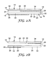
- FIGS. 2A and 2B illustrate exemplary embodiments of the sheets 14 that may be used to form the stacks 12, where like elements are similarly numbered.
- FIGS. 2A and 2B only two of the sheets 14 from the stack 12 are shown, and the sheets 14 are aligned with respect to each other as they are in the stack 12 but slightly separated for clarity concerning the portions of the sheets 14.
- Each of the sheets 14 comprises a rectangular member having first and second opposite ends 16 and 18 and a predetermined length between its first and second ends 16 and 18, and comprises a backing 20 having opposite major top and bottom side surfaces 22 and 24.
- the backing 20 comprises any suitable material, including paper and polymeric materials.
- backing 20 comprises a substantially transparent flexible polymeric material such as polyester.
- backing 20 is a 2.4 mil thick polyester.
- a layer of pressure sensitive adhesive 26 is on bottom surface 24 of backing 20.
- the sheets 14 are releasably adhered to each other by releasable adhesion of the layers of pressure sensitive adhesive 26 to the top surfaces 22 of underlying sheets 14 to form the stack 12 with adjacent ends 16 or 18 of the sheets 14 aligned and with the first and second ends 16 and 18 of successive sheets 14 in the stack 12 being adjacent.
- Suitable repositionable adhesives are disclosed in US Patent No. 3,691,140 (Silver ); 3,857,731 (Merrill et al .) ; 4,166,152 (Baker et al. ); 4,495,318 (Howard ); 5,045,569 (Delgado ); 5,073,457 (Blackwell ) and 5,571,617 (Cooprider et al .) , 5,663,241 (Takamatsu et al.
- the repositionable adhesive can be solvent based, or water based.
- each of the sheets 14 includes a layer 26 of pressure sensitive adhesive on at least a second end portion 34 of the bottom surface 24 adjacent the second end 18 of the backing 20.
- the sheets 14 in the stack 12 are releasably adhered to each other by adhesion of the layers of pressure sensitive adhesive 26 to portions of the top surfaces of underlying sheets 14 adjacent the first ends 16 of the underlying sheets 14 to form the stack 12 with adjacent ends 16 and 18 of the sheets 14 aligned and with the first and second ends 16 and 18 of successive sheets 14 in the stack 12 being adjacent.
- the second end portion 34 has a length from the second end 18 of the backing 20 toward its first end 16 that is longer than half the predetermined length of the backing 20.
- the second end portion 34 has a length from the second end 18 of the backing 20 toward its first end 16 that is shorter than half the predetermined length of the backing 20.
- the pressure sensitive adhesive in the layers 26 is repositionable, and the first end portions 32 of the sheets 14 are configured to prevent or reduce adhesion of the first end portions 32 of the sheets 14 adjacent their first ends 16 to an underlying sheet 14.
- the first end portion 32 is smaller in area than the second end portion 34, while in other embodiments the first end portion 32 is larger in area than the second end portion 34.
- the first end portion 32 is printed with a bright colored ink (e.g., red, green or yellow) to make it visually distinctive; while the adhesive coated second end portion 34 is generally transparent when adhered to a substrate so that it will not obscure a substrate to which it is attached.
- the top side surface 22 opposite the coating adhesive 26 is adapted to be written on by methods known in the art.
- the stacks 12 of sheets 14 are each supported on a single or common carrier member 38.
- a lowermost sheet 14 of each stack 12 is adhered or otherwise fixed along its full length to carrier member 38 to restrict endwise movement of the stacks 12 relative to the carrier member 38, and to restrict flexing of the second end portions 34 of all but the uppermost sheet 14 in the stack 12 around an axis parallel to the ends 16, 18 of the sheets 14 in the stack 12.
- the carrier member includes transverse side edges 39 substantially parallel to the first and second ends 16, 18 of the sheets 14. The distance between the transverse side edges 39 of the carrier member 38 is equal to or greater than the distance between the first and second ends 16, 18 of the sheets 14 of at least one of the plurality of stacks 12.
- the carrier member 38 is substantially flat. In another embodiment, the carrier member 38 is configured to bias or urge the stacks 12 toward top wall 46.
- a carrier member 38' may be formed from a resilient material and provided with an arcuate cross-sectional shape that is initially deflected toward bottom wall 44 when dispenser package 10 is new, and that resumes its arcuate shape as sheets 14 are dispensed from stacks 12.
- the stacks 12 secured to carrier member 38 may comprise sheets 14 having substantially similar construction, or may comprise sheets 14 having substantially different construction.
- the sheets 14 of one of the plurality of stacks 12 are formed from a polymeric material, and the sheets 14 of another one of the plurality of stacks 12 are formed from paper.
- the sheets 14 of one of the plurality of stacks 12 have a first size, and the sheets 14 of another one of the plurality of stacks 12 have a second size different from the first size.
- the sheets 14 having a first size have an end-to-end distance (i.e., from first end 16 to second end 18) greater than an end-to-end distance of the sheets 14 having a second size.
- the sheets 14 having a first size have a transverse width (i.e., parallel to first and second ends 16, 18) greater than a transverse width of the sheets 14 having a second size.
- the reduced adhesion or adhesive-free first end portions 32 of the sheets 14 of one of the plurality of stacks 12 are smaller in area than the adhesive-coated second end portions 34, and the reduced adhesion or adhesive-free first end portions 32 of the sheets 14 of another one of the plurality of stacks 12 are larger in area than the adhesive-coated second end portions 34.
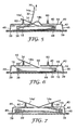
- the dispenser package 10 also includes an enclosure 40 comprising walls defining a chamber 42 in which the carrier member 38 with stacks 12 secured thereto is positioned.
- Those walls include a bottom wall 44, a top wall 46 opposite the bottom wall 44, and transverse upstanding side walls 48 extending between the bottom walls 44 and top wall 46.
- the top wall 46 defines a top side of the chamber 42, and further defines a generally central transverse slot 50 substantially parallel to the first and second ends 16, 18 of the sheets 14.
- the top wall 46 is positioned adjacent an uppermost sheet 14 of each of the plurality of stacks 12 (which uppermost sheet is identified as 14a in FIGS.
- top wall 46 and side walls 48 comprise molded plastic
- bottom wall 44 comprises a paper or cardstock material to which the molded plastic top and side walls are secured, as by an adhesive.
- the transverse side walls 48 are substantially parallel to the first and second ends 16, 18 of the sheets 14, and are spaced from the transverse side edges of the carrier member 38 and the first and second ends 16, 18 of the sheets 14 to afford limited end-to-end movement (e.g. shuttling) of the carrier member 38 and stacks 12 of sheets 14 thereon within the chamber 42 and thus provide relative movement between the slot 50 and the uppermost sheets 14a.
- end-to-end movement e.g. shuttling
- the carrier member 38 and side walls 48 are sized and positioned such that the distance between the transverse side edges 39 of the carrier member 38 is in the range of 88 to 98 percent of the distance between the transverse side walls 48 of the enclosure 40.
- carrier member 38 and chamber 42 are also dimensioned to afford limited movement of carrier member 38 in a direction parallel to transverse side edges 39 (and first and second ends 16, 18 of sheets 14), such that carrier member 38 and stacks 12 thereon move or "float" within chamber 42 in three dimensions.
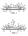
- the relative movement between the portion of the top wall 46 defining the slot 50 and the uppermost sheet 14a from an initial carrier member 38 position ( FIG. 3 ) to a final carrier member 38 position ( FIGS. 4-5 ) affords, as the uppermost sheet 14a is manually pulled through the slot 50, alignment of the slot 50 with successive portions of the uppermost sheet 14a toward the second end 18 of the uppermost sheet 14a as the successive portions are peeled from an underlying sheet 14 in the stack 34 (identified as 14b in FIGS. 3 through 7 ) to which the uppermost sheet 14a is adhered.
- the slot 50 is located to afford transverse folding of the underlying sheet 14b ( FIG.
- the slot 50 is substantially centrally positioned between the first and second ends 16, 18 of the sheets 14 in both the initial and final carrier member 38 positions.
- the slot 50 is dimensioned such that at least a portion of the slot 50 is positioned over a mid-point between the first and second ends 16, 18 of the sheets 14 in both the initial and final carrier member 38 positions.
- the uppermost sheet 14a on each of the plurality of stacks 12 is resiliently bent so that first ends 16 and first end portions 32 project through the slot 50 and rest against an abutment surface 60 on top wall 46 adjacent opposing sides of slot 50.
- the abutment surfaces 60 insure the first end portions 32 of the sheets 14a projecting through the slot 50 are spaced from the top wall 46, so that the first end portion 32 may be easily grasped by a user.
- the abutment surfaces 60 because of the relationship between the abutment surfaces 60 and the position of the adhesive 26, release coatings 28, 30, and/or tabs 37 as described with respect to FIGS.
- the first end portions 32 of the uppermost sheets 14 are disposed at an angle with respect to the second end portion 34 of the uppermost sheet 14 that is adhered to the first underlying sheet 14 in the stack 12, such that a user may easily grasp the first end portion 32 of a desired sheet 14a.
- the width of slot 50 is selected to help prevent a phenomenon in which more than one sheet 14 is pulled through the slot 50 by the uppermost sheet 14a being removed which may occur if contact occurs between folded first portion 32 and adhesive coated second portion 34 of the underlying sheet 14b as the underlying sheet 14b is pulled from the dispenser package 10 by the uppermost sheet 14a, and which phenomenon is exacerbated when that uppermost sheet 14a is pulled in a direction generally parallel to the top wall 46 rather than at a right angle thereto.
- abutment surfaces 60 are at least about 0.5 centimeter (0.2 inch) long in a direction normal to the top surface of the top wall 46 and spaced about 1.5 to 2.0 centimeters (0.6 to 0.8 inches).
- the dispenser package 10 comprises four stacks 12 of sheets 14.
- the stacks 12 have dimensions of approximately 1.5 inches by 2 inches (3.8 cm by 5.1 cm), 1.5 inches by 1 inch (3.8 cm by 2.5 cm), 1.5 inches by 0.5 inches (3.8 cm by 1.3 cm), and 1.5 inches by 0.5 inches (3.8 cm by 1.3 cm) and are each of a different color.
- the stacks 12 are attached to a carrier member 38 made from 22 mil PET film having dimensions of approximately 2.01 inches by 4.66 inches (5.1 cm by 11.8 cm).
- the stacks 12 are separated from each other on the carrier member 12 by a distance of approximately 0.02 inches (0.5 mm).
- the transverse side walls 48 of the enclosure 40 are spaced apart by a distance of approximately 2.17 inches (5.5 cm), such that the carrier member 38 width of 2.01 inches (5.1 cm) is approximately 93% of the distance between side walls 48.
- Slot 50 is centrally positioned between side walls 48 and has a width of approximately 0.375 inches (0.95 cm).
Landscapes
- Engineering & Computer Science (AREA)
- Mechanical Engineering (AREA)
- Containers And Packaging Bodies Having A Special Means To Remove Contents (AREA)
- Laminated Bodies (AREA)
Applications Claiming Priority (2)
| Application Number | Priority Date | Filing Date | Title |
|---|---|---|---|
| US11/341,293 US7494027B2 (en) | 2006-01-27 | 2006-01-27 | Dispenser package |
| PCT/US2007/001074 WO2007089422A1 (en) | 2006-01-27 | 2007-01-16 | Dispenser package |
Publications (3)
| Publication Number | Publication Date |
|---|---|
| EP1976783A1 EP1976783A1 (en) | 2008-10-08 |
| EP1976783A4 EP1976783A4 (en) | 2012-12-26 |
| EP1976783B1 true EP1976783B1 (en) | 2015-02-25 |
Family
ID=38321029
Family Applications (1)
| Application Number | Title | Priority Date | Filing Date |
|---|---|---|---|
| EP07762822.0A Not-in-force EP1976783B1 (en) | 2006-01-27 | 2007-01-16 | Dispenser package |
Country Status (6)
| Country | Link |
|---|---|
| US (1) | US7494027B2 (enExample) |
| EP (1) | EP1976783B1 (enExample) |
| JP (1) | JP5080499B2 (enExample) |
| KR (1) | KR101279273B1 (enExample) |
| CN (1) | CN101374742B (enExample) |
| WO (1) | WO2007089422A1 (enExample) |
Families Citing this family (15)
| Publication number | Priority date | Publication date | Assignee | Title |
|---|---|---|---|---|
| US8418879B2 (en) * | 2005-08-31 | 2013-04-16 | Kimberly-Clark Worldwide, Inc. | Pop-up bath tissue product |
| US20080130209A1 (en) * | 2006-12-01 | 2008-06-05 | Dilip Bhavnani | Calculator letter opener |
| USD581978S1 (en) | 2007-08-22 | 2008-12-02 | 3M Innovative Properties Company | Writing instrument with sheet dispenser |
| US20090052973A1 (en) * | 2007-08-22 | 2009-02-26 | 3M Innovative Properties Company | Writing instrument with compact sheet dispenser |
| US20090050646A1 (en) * | 2007-08-22 | 2009-02-26 | 3M Innovative Properties Company | Compact sheet dispenser |
| EP2371576A1 (en) * | 2010-04-01 | 2011-10-05 | Possibillion | An assembly of a container and a plurality of note pads |
| USD665810S1 (en) * | 2010-07-28 | 2012-08-21 | Openpeak, Inc. | Cover for tablet computer |
| US20140087116A1 (en) * | 2010-08-27 | 2014-03-27 | Christopher D. GLATT | High-speed masking tape apparatus and method |
| USD641416S1 (en) * | 2010-09-30 | 2011-07-12 | Jour David C T | Notepaper holder |
| USD641417S1 (en) * | 2010-09-30 | 2011-07-12 | Jour David C T | Notepaper holder |
| USD641418S1 (en) * | 2010-11-29 | 2011-07-12 | Jour David C T | Notepaper holder |
| JP5952531B2 (ja) * | 2011-05-12 | 2016-07-13 | 株式会社カンミ堂 | シートディスペンサー |
| US20130168404A1 (en) * | 2011-12-28 | 2013-07-04 | David C.T. Jour | Removable notepaper dispenser |
| JP2017087671A (ja) * | 2015-11-16 | 2017-05-25 | 信 藤澤 | 付箋収納具 |
| WO2017147028A1 (en) * | 2016-02-22 | 2017-08-31 | 3M Innovative Properties Company | Assembly for dispensing full adhesive notes |
Family Cites Families (22)
| Publication number | Priority date | Publication date | Assignee | Title |
|---|---|---|---|---|
| US3691140A (en) * | 1970-03-09 | 1972-09-12 | Spencer Ferguson Silver | Acrylate copolymer microspheres |
| US3857731A (en) * | 1973-04-06 | 1974-12-31 | Minnesota Mining & Mfg | Acrylate microsphere-surfaced sheet material |
| US4166152B1 (en) * | 1977-08-17 | 1999-05-18 | Minnesota Mining & Mfg | Tacky polymeric microspheres |
| US4781306A (en) * | 1981-02-19 | 1988-11-01 | Minnesota Mining And Manufacturing Company | Stack of sheet material |
| US4416392A (en) * | 1981-02-19 | 1983-11-22 | Minnesota Mining & Manufacturing Company | Dispenser for adhesive coated sheet material |
| US4770320A (en) * | 1987-06-03 | 1988-09-13 | Minnesota Mining And Manufacturing Company | Sheet and dispenser package therefor |
| US4907825A (en) * | 1987-06-03 | 1990-03-13 | Minnesota Mining And Manufacturing Company | Sheet and dispenser package therefor |
| US4993590A (en) * | 1989-05-26 | 1991-02-19 | Minnesota Mining And Manufacturing Company | Sheet dispenser |
| US5158205A (en) * | 1991-01-11 | 1992-10-27 | Minnesota Mining And Manufacturing Company | Dispenser for a small stack of note paper |
| US5571617A (en) * | 1993-04-23 | 1996-11-05 | Minnesota Mining And Manufacturing Company | Pressure sensitive adhesive comprising tacky surface active microspheres |
| US5769270A (en) * | 1993-11-25 | 1998-06-23 | Minnesota Mining And Manufacturing Company | Tape or sheet dispenser |
| US5551595A (en) * | 1994-06-30 | 1996-09-03 | Minnesota Mining And Manufacturing Company | Dispenser package for use in ring binders |
| US5663241A (en) * | 1994-12-13 | 1997-09-02 | Minnesota Mining And Manufacturing Company | Removable pressure sensitive adhesive and article |
| JP3588161B2 (ja) | 1995-05-19 | 2004-11-10 | ミネソタ マイニング アンド マニュファクチャリング カンパニー | メモ用紙積重体補充用ユニット |
| US5714237A (en) * | 1996-01-16 | 1998-02-03 | Minnesota Mining Manufacturing Company | Partially crosslinked microspheres |
| US5755356A (en) * | 1996-04-15 | 1998-05-26 | Minnesota Mining And Manufacturing Company | Compressible sheet dispenser |
| US5824748A (en) * | 1996-06-03 | 1998-10-20 | Minnesota Mining And Manufacturing Company | Composite pressure sensitive adhesive microspheres |
| US5755337A (en) * | 1996-06-04 | 1998-05-26 | Linn; Maynard W. | Record keeping holder for food storage retrieval |
| US5756625A (en) * | 1996-10-11 | 1998-05-26 | Minnesota Mining And Manufacturing Company | Stabilized adhesive microspheres |
| US6514585B1 (en) * | 1998-11-13 | 2003-02-04 | 3M Innovative Properties Company | Tape strip pads and dispenser and method of dispensing individual tape strips |
| US6681452B1 (en) * | 2002-09-27 | 2004-01-27 | Adstracts, Inc. | Clamping apparatus with removable attachments |
| USD508955S1 (en) * | 2005-01-05 | 2005-08-30 | Kudos Finder Tape Industrial Co., Ltd. | Memo slip dispenser |
-
2006
- 2006-01-27 US US11/341,293 patent/US7494027B2/en not_active Expired - Fee Related
-
2007
- 2007-01-16 EP EP07762822.0A patent/EP1976783B1/en not_active Not-in-force
- 2007-01-16 KR KR1020087019443A patent/KR101279273B1/ko not_active Expired - Fee Related
- 2007-01-16 WO PCT/US2007/001074 patent/WO2007089422A1/en not_active Ceased
- 2007-01-16 JP JP2008552320A patent/JP5080499B2/ja not_active Expired - Fee Related
- 2007-01-16 CN CN2007800037042A patent/CN101374742B/zh not_active Expired - Fee Related
Also Published As
| Publication number | Publication date |
|---|---|
| JP2009524559A (ja) | 2009-07-02 |
| CN101374742A (zh) | 2009-02-25 |
| CN101374742B (zh) | 2012-08-22 |
| US7494027B2 (en) | 2009-02-24 |
| US20070175913A1 (en) | 2007-08-02 |
| EP1976783A1 (en) | 2008-10-08 |
| EP1976783A4 (en) | 2012-12-26 |
| KR101279273B1 (ko) | 2013-06-26 |
| KR20080107365A (ko) | 2008-12-10 |
| WO2007089422A1 (en) | 2007-08-09 |
| JP5080499B2 (ja) | 2012-11-21 |
Similar Documents
| Publication | Publication Date | Title |
|---|---|---|
| EP1976783B1 (en) | Dispenser package | |
| JP2835713B2 (ja) | シート及びそのための小出し器パッケージ | |
| US4907825A (en) | Sheet and dispenser package therefor | |
| US7185785B2 (en) | Tape sheet pads and dispenser and method of dispensing individual tape sheets from such pads | |
| US5411168A (en) | Sheet dispenser and dispenser subassemblies | |
| EP0646477B1 (en) | Sheet dispenser | |
| WO2008033726A1 (en) | Marking device | |
| AU718058B2 (en) | Adhesive tape strip and tape flag pads with center tabbed leader strip | |
| US5697518A (en) | Header padded stationery equipped with adhesive sheet pads recessed within the header | |
| US6703096B2 (en) | Combination sheet pad | |
| CN101784396A (zh) | 紧凑型片材分配器 | |
| KR101143675B1 (ko) | 접착성 클립 조립체 | |
| EP0365055B1 (en) | Sheet and dispenser package thereof |
Legal Events
| Date | Code | Title | Description |
|---|---|---|---|
| PUAI | Public reference made under article 153(3) epc to a published international application that has entered the european phase |
Free format text: ORIGINAL CODE: 0009012 |
|
| 17P | Request for examination filed |
Effective date: 20080804 |
|
| AK | Designated contracting states |
Kind code of ref document: A1 Designated state(s): AT BE BG CH CY CZ DE DK EE ES FI FR GB GR HU IE IS IT LI LT LU LV MC NL PL PT RO SE SI SK TR |
|
| DAX | Request for extension of the european patent (deleted) | ||
| A4 | Supplementary search report drawn up and despatched |
Effective date: 20121123 |
|
| RIC1 | Information provided on ipc code assigned before grant |
Ipc: B65C 11/00 20060101ALI20121119BHEP Ipc: B65H 1/00 20060101ALI20121119BHEP Ipc: B65D 83/08 20060101ALI20121119BHEP Ipc: B42D 5/00 20060101ALI20121119BHEP Ipc: B65H 1/04 20060101AFI20121119BHEP |
|
| 17Q | First examination report despatched |
Effective date: 20130917 |
|
| GRAP | Despatch of communication of intention to grant a patent |
Free format text: ORIGINAL CODE: EPIDOSNIGR1 |
|
| INTG | Intention to grant announced |
Effective date: 20140901 |
|
| GRAS | Grant fee paid |
Free format text: ORIGINAL CODE: EPIDOSNIGR3 |
|
| GRAA | (expected) grant |
Free format text: ORIGINAL CODE: 0009210 |
|
| AK | Designated contracting states |
Kind code of ref document: B1 Designated state(s): AT BE BG CH CY CZ DE DK EE ES FI FR GB GR HU IE IS IT LI LT LU LV MC NL PL PT RO SE SI SK TR |
|
| REG | Reference to a national code |
Ref country code: GB Ref legal event code: FG4D |
|
| REG | Reference to a national code |
Ref country code: CH Ref legal event code: EP |
|
| REG | Reference to a national code |
Ref country code: IE Ref legal event code: FG4D |
|
| REG | Reference to a national code |
Ref country code: DE Ref legal event code: R096 Ref document number: 602007040354 Country of ref document: DE Effective date: 20150409 |
|
| REG | Reference to a national code |
Ref country code: AT Ref legal event code: REF Ref document number: 711751 Country of ref document: AT Kind code of ref document: T Effective date: 20150415 |
|
| REG | Reference to a national code |
Ref country code: NL Ref legal event code: VDEP Effective date: 20150225 |
|
| REG | Reference to a national code |
Ref country code: AT Ref legal event code: MK05 Ref document number: 711751 Country of ref document: AT Kind code of ref document: T Effective date: 20150225 |
|
| REG | Reference to a national code |
Ref country code: LT Ref legal event code: MG4D |
|
| PG25 | Lapsed in a contracting state [announced via postgrant information from national office to epo] |
Ref country code: SE Free format text: LAPSE BECAUSE OF FAILURE TO SUBMIT A TRANSLATION OF THE DESCRIPTION OR TO PAY THE FEE WITHIN THE PRESCRIBED TIME-LIMIT Effective date: 20150225 Ref country code: FI Free format text: LAPSE BECAUSE OF FAILURE TO SUBMIT A TRANSLATION OF THE DESCRIPTION OR TO PAY THE FEE WITHIN THE PRESCRIBED TIME-LIMIT Effective date: 20150225 Ref country code: ES Free format text: LAPSE BECAUSE OF FAILURE TO SUBMIT A TRANSLATION OF THE DESCRIPTION OR TO PAY THE FEE WITHIN THE PRESCRIBED TIME-LIMIT Effective date: 20150225 Ref country code: LT Free format text: LAPSE BECAUSE OF FAILURE TO SUBMIT A TRANSLATION OF THE DESCRIPTION OR TO PAY THE FEE WITHIN THE PRESCRIBED TIME-LIMIT Effective date: 20150225 |
|
| PG25 | Lapsed in a contracting state [announced via postgrant information from national office to epo] |
Ref country code: AT Free format text: LAPSE BECAUSE OF FAILURE TO SUBMIT A TRANSLATION OF THE DESCRIPTION OR TO PAY THE FEE WITHIN THE PRESCRIBED TIME-LIMIT Effective date: 20150225 Ref country code: IS Free format text: LAPSE BECAUSE OF FAILURE TO SUBMIT A TRANSLATION OF THE DESCRIPTION OR TO PAY THE FEE WITHIN THE PRESCRIBED TIME-LIMIT Effective date: 20150625 Ref country code: LV Free format text: LAPSE BECAUSE OF FAILURE TO SUBMIT A TRANSLATION OF THE DESCRIPTION OR TO PAY THE FEE WITHIN THE PRESCRIBED TIME-LIMIT Effective date: 20150225 Ref country code: GR Free format text: LAPSE BECAUSE OF FAILURE TO SUBMIT A TRANSLATION OF THE DESCRIPTION OR TO PAY THE FEE WITHIN THE PRESCRIBED TIME-LIMIT Effective date: 20150526 |
|
| PG25 | Lapsed in a contracting state [announced via postgrant information from national office to epo] |
Ref country code: NL Free format text: LAPSE BECAUSE OF FAILURE TO SUBMIT A TRANSLATION OF THE DESCRIPTION OR TO PAY THE FEE WITHIN THE PRESCRIBED TIME-LIMIT Effective date: 20150225 |
|
| PG25 | Lapsed in a contracting state [announced via postgrant information from national office to epo] |
Ref country code: SK Free format text: LAPSE BECAUSE OF FAILURE TO SUBMIT A TRANSLATION OF THE DESCRIPTION OR TO PAY THE FEE WITHIN THE PRESCRIBED TIME-LIMIT Effective date: 20150225 Ref country code: DK Free format text: LAPSE BECAUSE OF FAILURE TO SUBMIT A TRANSLATION OF THE DESCRIPTION OR TO PAY THE FEE WITHIN THE PRESCRIBED TIME-LIMIT Effective date: 20150225 Ref country code: CZ Free format text: LAPSE BECAUSE OF FAILURE TO SUBMIT A TRANSLATION OF THE DESCRIPTION OR TO PAY THE FEE WITHIN THE PRESCRIBED TIME-LIMIT Effective date: 20150225 Ref country code: EE Free format text: LAPSE BECAUSE OF FAILURE TO SUBMIT A TRANSLATION OF THE DESCRIPTION OR TO PAY THE FEE WITHIN THE PRESCRIBED TIME-LIMIT Effective date: 20150225 Ref country code: RO Free format text: LAPSE BECAUSE OF FAILURE TO SUBMIT A TRANSLATION OF THE DESCRIPTION OR TO PAY THE FEE WITHIN THE PRESCRIBED TIME-LIMIT Effective date: 20150225 |
|
| REG | Reference to a national code |
Ref country code: DE Ref legal event code: R097 Ref document number: 602007040354 Country of ref document: DE |
|
| PG25 | Lapsed in a contracting state [announced via postgrant information from national office to epo] |
Ref country code: PL Free format text: LAPSE BECAUSE OF FAILURE TO SUBMIT A TRANSLATION OF THE DESCRIPTION OR TO PAY THE FEE WITHIN THE PRESCRIBED TIME-LIMIT Effective date: 20150225 |
|
| REG | Reference to a national code |
Ref country code: FR Ref legal event code: PLFP Year of fee payment: 10 |
|
| PG25 | Lapsed in a contracting state [announced via postgrant information from national office to epo] |
Ref country code: IT Free format text: LAPSE BECAUSE OF FAILURE TO SUBMIT A TRANSLATION OF THE DESCRIPTION OR TO PAY THE FEE WITHIN THE PRESCRIBED TIME-LIMIT Effective date: 20150225 |
|
| PLBE | No opposition filed within time limit |
Free format text: ORIGINAL CODE: 0009261 |
|
| STAA | Information on the status of an ep patent application or granted ep patent |
Free format text: STATUS: NO OPPOSITION FILED WITHIN TIME LIMIT |
|
| 26N | No opposition filed |
Effective date: 20151126 |
|
| PG25 | Lapsed in a contracting state [announced via postgrant information from national office to epo] |
Ref country code: SI Free format text: LAPSE BECAUSE OF FAILURE TO SUBMIT A TRANSLATION OF THE DESCRIPTION OR TO PAY THE FEE WITHIN THE PRESCRIBED TIME-LIMIT Effective date: 20150225 |
|
| PGFP | Annual fee paid to national office [announced via postgrant information from national office to epo] |
Ref country code: FR Payment date: 20151208 Year of fee payment: 10 |
|
| PGFP | Annual fee paid to national office [announced via postgrant information from national office to epo] |
Ref country code: DE Payment date: 20160112 Year of fee payment: 10 |
|
| PG25 | Lapsed in a contracting state [announced via postgrant information from national office to epo] |
Ref country code: BE Free format text: LAPSE BECAUSE OF FAILURE TO SUBMIT A TRANSLATION OF THE DESCRIPTION OR TO PAY THE FEE WITHIN THE PRESCRIBED TIME-LIMIT Effective date: 20150225 |
|
| PGFP | Annual fee paid to national office [announced via postgrant information from national office to epo] |
Ref country code: GB Payment date: 20160113 Year of fee payment: 10 |
|
| PG25 | Lapsed in a contracting state [announced via postgrant information from national office to epo] |
Ref country code: LU Free format text: LAPSE BECAUSE OF FAILURE TO SUBMIT A TRANSLATION OF THE DESCRIPTION OR TO PAY THE FEE WITHIN THE PRESCRIBED TIME-LIMIT Effective date: 20160116 |
|
| REG | Reference to a national code |
Ref country code: CH Ref legal event code: PL |
|
| PG25 | Lapsed in a contracting state [announced via postgrant information from national office to epo] |
Ref country code: MC Free format text: LAPSE BECAUSE OF FAILURE TO SUBMIT A TRANSLATION OF THE DESCRIPTION OR TO PAY THE FEE WITHIN THE PRESCRIBED TIME-LIMIT Effective date: 20150225 |
|
| PG25 | Lapsed in a contracting state [announced via postgrant information from national office to epo] |
Ref country code: LI Free format text: LAPSE BECAUSE OF NON-PAYMENT OF DUE FEES Effective date: 20160131 Ref country code: CH Free format text: LAPSE BECAUSE OF NON-PAYMENT OF DUE FEES Effective date: 20160131 |
|
| REG | Reference to a national code |
Ref country code: IE Ref legal event code: MM4A |
|
| PG25 | Lapsed in a contracting state [announced via postgrant information from national office to epo] |
Ref country code: IE Free format text: LAPSE BECAUSE OF NON-PAYMENT OF DUE FEES Effective date: 20160116 |
|
| REG | Reference to a national code |
Ref country code: DE Ref legal event code: R119 Ref document number: 602007040354 Country of ref document: DE |
|
| GBPC | Gb: european patent ceased through non-payment of renewal fee |
Effective date: 20170116 |
|
| REG | Reference to a national code |
Ref country code: FR Ref legal event code: ST Effective date: 20170929 |
|
| PG25 | Lapsed in a contracting state [announced via postgrant information from national office to epo] |
Ref country code: FR Free format text: LAPSE BECAUSE OF NON-PAYMENT OF DUE FEES Effective date: 20170131 |
|
| PG25 | Lapsed in a contracting state [announced via postgrant information from national office to epo] |
Ref country code: GB Free format text: LAPSE BECAUSE OF NON-PAYMENT OF DUE FEES Effective date: 20170116 Ref country code: DE Free format text: LAPSE BECAUSE OF NON-PAYMENT OF DUE FEES Effective date: 20170801 |
|
| PG25 | Lapsed in a contracting state [announced via postgrant information from national office to epo] |
Ref country code: HU Free format text: LAPSE BECAUSE OF FAILURE TO SUBMIT A TRANSLATION OF THE DESCRIPTION OR TO PAY THE FEE WITHIN THE PRESCRIBED TIME-LIMIT; INVALID AB INITIO Effective date: 20070116 Ref country code: CY Free format text: LAPSE BECAUSE OF FAILURE TO SUBMIT A TRANSLATION OF THE DESCRIPTION OR TO PAY THE FEE WITHIN THE PRESCRIBED TIME-LIMIT Effective date: 20150225 |
|
| PG25 | Lapsed in a contracting state [announced via postgrant information from national office to epo] |
Ref country code: PT Free format text: LAPSE BECAUSE OF FAILURE TO SUBMIT A TRANSLATION OF THE DESCRIPTION OR TO PAY THE FEE WITHIN THE PRESCRIBED TIME-LIMIT Effective date: 20150225 Ref country code: TR Free format text: LAPSE BECAUSE OF FAILURE TO SUBMIT A TRANSLATION OF THE DESCRIPTION OR TO PAY THE FEE WITHIN THE PRESCRIBED TIME-LIMIT Effective date: 20150225 |
|
| PG25 | Lapsed in a contracting state [announced via postgrant information from national office to epo] |
Ref country code: BG Free format text: LAPSE BECAUSE OF FAILURE TO SUBMIT A TRANSLATION OF THE DESCRIPTION OR TO PAY THE FEE WITHIN THE PRESCRIBED TIME-LIMIT Effective date: 20150225 |