EP1974081B1 - Elastic silicone rubber belt - Google Patents
Elastic silicone rubber belt Download PDFInfo
- Publication number
- EP1974081B1 EP1974081B1 EP06848036A EP06848036A EP1974081B1 EP 1974081 B1 EP1974081 B1 EP 1974081B1 EP 06848036 A EP06848036 A EP 06848036A EP 06848036 A EP06848036 A EP 06848036A EP 1974081 B1 EP1974081 B1 EP 1974081B1
- Authority
- EP
- European Patent Office
- Prior art keywords
- fibers
- belt
- elastic yarns
- rubber
- rubber belt
- Prior art date
- Legal status (The legal status is an assumption and is not a legal conclusion. Google has not performed a legal analysis and makes no representation as to the accuracy of the status listed.)
- Active
Links
- 229920002379 silicone rubber Polymers 0.000 title claims abstract description 36
- 239000004945 silicone rubber Substances 0.000 title claims abstract description 34
- 239000000835 fiber Substances 0.000 claims abstract description 55
- 229920001971 elastomer Polymers 0.000 claims abstract description 38
- 239000005060 rubber Substances 0.000 claims abstract description 38
- 238000004519 manufacturing process Methods 0.000 claims abstract description 17
- 238000000034 method Methods 0.000 claims abstract description 16
- 239000007788 liquid Substances 0.000 claims abstract description 4
- 238000010438 heat treatment Methods 0.000 claims abstract 3
- 239000004753 textile Substances 0.000 claims description 25
- 229920002334 Spandex Polymers 0.000 claims description 6
- 239000013013 elastic material Substances 0.000 claims description 6
- 229920003052 natural elastomer Polymers 0.000 claims description 6
- 229920001194 natural rubber Polymers 0.000 claims description 6
- 244000043261 Hevea brasiliensis Species 0.000 claims description 3
- 239000002318 adhesion promoter Substances 0.000 claims description 3
- GQSGZTBDVNUIQS-DGCLKSJQSA-N ciclonicate Chemical compound C1C(C)(C)C[C@H](C)C[C@H]1OC(=O)C1=CC=CN=C1 GQSGZTBDVNUIQS-DGCLKSJQSA-N 0.000 claims description 3
- 239000004759 spandex Substances 0.000 claims description 3
- 229920000459 Nitrile rubber Polymers 0.000 claims description 2
- 239000004944 Liquid Silicone Rubber Substances 0.000 claims 1
- 239000004744 fabric Substances 0.000 description 24
- 239000010410 layer Substances 0.000 description 22
- 238000009998 heat setting Methods 0.000 description 11
- 230000032798 delamination Effects 0.000 description 5
- 238000004043 dyeing Methods 0.000 description 4
- 238000010073 coating (rubber) Methods 0.000 description 3
- 238000012986 modification Methods 0.000 description 3
- 230000004048 modification Effects 0.000 description 3
- 239000000126 substance Substances 0.000 description 3
- 229920003051 synthetic elastomer Polymers 0.000 description 3
- 239000005061 synthetic rubber Substances 0.000 description 3
- 229910000831 Steel Inorganic materials 0.000 description 2
- 238000004061 bleaching Methods 0.000 description 2
- 239000011248 coating agent Substances 0.000 description 2
- 238000000576 coating method Methods 0.000 description 2
- 238000005520 cutting process Methods 0.000 description 2
- 239000002356 single layer Substances 0.000 description 2
- 239000010959 steel Substances 0.000 description 2
- 229920002994 synthetic fiber Polymers 0.000 description 2
- 239000012209 synthetic fiber Substances 0.000 description 2
- 238000009988 textile finishing Methods 0.000 description 2
- 229920000742 Cotton Polymers 0.000 description 1
- 238000010276 construction Methods 0.000 description 1
- 210000004177 elastic tissue Anatomy 0.000 description 1
- 238000009940 knitting Methods 0.000 description 1
- 239000000463 material Substances 0.000 description 1
- 239000000203 mixture Substances 0.000 description 1
- 238000012856 packing Methods 0.000 description 1
- 238000002360 preparation method Methods 0.000 description 1
- 230000003014 reinforcing effect Effects 0.000 description 1
- 238000009877 rendering Methods 0.000 description 1
- 238000004904 shortening Methods 0.000 description 1
- 229920001169 thermoplastic Polymers 0.000 description 1
- 239000004416 thermosoftening plastic Substances 0.000 description 1
- 238000011282 treatment Methods 0.000 description 1
- -1 wool Polymers 0.000 description 1
- 210000002268 wool Anatomy 0.000 description 1
Images


Classifications
-
- D—TEXTILES; PAPER
- D06—TREATMENT OF TEXTILES OR THE LIKE; LAUNDERING; FLEXIBLE MATERIALS NOT OTHERWISE PROVIDED FOR
- D06C—FINISHING, DRESSING, TENTERING OR STRETCHING TEXTILE FABRICS
- D06C7/00—Heating or cooling textile fabrics
-
- B—PERFORMING OPERATIONS; TRANSPORTING
- B29—WORKING OF PLASTICS; WORKING OF SUBSTANCES IN A PLASTIC STATE IN GENERAL
- B29D—PRODUCING PARTICULAR ARTICLES FROM PLASTICS OR FROM SUBSTANCES IN A PLASTIC STATE
- B29D29/00—Producing belts or bands
-
- D—TEXTILES; PAPER
- D06—TREATMENT OF TEXTILES OR THE LIKE; LAUNDERING; FLEXIBLE MATERIALS NOT OTHERWISE PROVIDED FOR
- D06C—FINISHING, DRESSING, TENTERING OR STRETCHING TEXTILE FABRICS
- D06C21/00—Shrinking by compressing
-
- D—TEXTILES; PAPER
- D06—TREATMENT OF TEXTILES OR THE LIKE; LAUNDERING; FLEXIBLE MATERIALS NOT OTHERWISE PROVIDED FOR
- D06C—FINISHING, DRESSING, TENTERING OR STRETCHING TEXTILE FABRICS
- D06C21/00—Shrinking by compressing
- D06C21/005—Compacting belts
-
- B—PERFORMING OPERATIONS; TRANSPORTING
- B29—WORKING OF PLASTICS; WORKING OF SUBSTANCES IN A PLASTIC STATE IN GENERAL
- B29K—INDEXING SCHEME ASSOCIATED WITH SUBCLASSES B29B, B29C OR B29D, RELATING TO MOULDING MATERIALS OR TO MATERIALS FOR MOULDS, REINFORCEMENTS, FILLERS OR PREFORMED PARTS, e.g. INSERTS
- B29K2083/00—Use of polymers having silicon, with or without sulfur, nitrogen, oxygen, or carbon only, in the main chain, as moulding material
- B29K2083/005—LSR, i.e. liquid silicone rubbers, or derivatives thereof
Definitions
- the instant invention relates generally to the production of textiles. More specifically, the instant invention relates to a textile machine belt that is used in the textile finishing process.
- circular knit fabrics may be required to undergo successive processing operations during the preparation, dyeing, finishing and making-up thereof both in tubular form, as they descend from the circular knitting machine, and in open form, obtained by cutting the tubular fabric along one of its side edges.
- the fabric is subjected to a heat setting operation.
- heat setting is performed on fabrics composed of or partly containing synthetic fibers, such as thermoplastic fibers. The aim of heat setting is to fix the dimensions and the flat state of the surfaces of the fabric thereby providing the fabric with stability. Heat setting a fabric also eliminates permanent creases or distortions that occur during the course of processing in bleaching and dyeing machines.
- the tubular fabric is guided by means of a flat expansion device and is fed in a flattened form between the surface of a heated steel cylinder and an endless felt belt.
- the main drawbacks of these machines include the squashing of the side edges of the tubular fabric and a non-uniform heat exchange on its two surfaces.
- the tubular fabric is guided by means of a flat expansion device which accompanies it in a flattened form through a horizontal or vertical chamber until it emerges therefrom. Inside the chamber, the two surfaces of the tubular fabric are acted on by flows of hot air. The heat exchange on the two surfaces of the fabric, however, is inadequate.
- an elastic belt having a definite length is used.
- the definite length elastic belt elongates from 50 to 70% of its original length.
- rubber and nitrile rubber belts reinforced with yarns or fibers having a standard elasticity are used in the new manufacturing process.
- belts made only with rubber have also been used.
- These types of belts have exhibited a short service life when used in the new textile manufacturing process.
- the service life of these prior belts are shortened even more when subjected to the elevated temperatures in the heat setting sections of the textile manufacturing machine. Therefore, the temperatures that can be used in the manufacturing process are limited.
- the prior rubber belts experience excessive shortening in width in the cross-machine (CD) direction when elongated in the machine (MD) direction, which creates problems in the manufacturing process.
- GB-A-1 030 354 and GB-A-1 088 066 disclose belts having a textile base and including silicon rubber. However, these documents do not address the aforesaid technical problem.
- Yet another object of the invention is to provide a rubber belt that is capable of elongating from 50 to 70% of its original length.
- a further obj ect of the invention is to provide a rubber belt that does not substantially shrink in the CD direction while it elongates in the MD direction.
- a still further object of the invention is to provide a rubber belt that resists delamination when elongating.
- Yet another objective of the invention is to provide a rubber belt that is capable of being used to produce a variety of textiles.
- a still further objective of the instant invention is to provide a rubber belt that is more durable, resulting in an increased service life.
- the instant invention is directed to a machine belt that is used to manufacture textiles.
- the instant belt is a rubber belt comprising at least one layer of tightly packed elastic yarns or fibers and a layer of silicone rubber.
- the elastic yarns or fibers are tightly packed in order to allow the belt to elongate in length in the MD direction while the belt's width in the CD direction remains substantially unchanged.
- the instant invention is directed to a method of manufacturing a textile machine rubber belt.
- the method comprises wrapping one or more elastic yarns or fibers onto a mandrel or around two substantially parallel rolls, wherein the one or more elastic yarns or fibers form one or more layers on the mandrel or the substantially parallel rolls.
- a liquid high viscosity silicone rubber is added on top of the one or more yarns layers. After the silicone rubber is added, the mandrel or the two substantially parallel rolls and the added silicone rubber, are heated in order to polymerize the silicone rubber.
- the instant invention relates to a textile machine silicone rubber belt that is reinforced with a structure comprised of elastic yarns or fibers.
- an elastic yarn or fiber is a yam or fiber with an elongation at its breaking point of between 40 and 400% of its original length.
- a coating system was used. That is, an endless base fabric was constructed and coated with silicone rubber. In order to have good mechanical properties, the belt was constructed to have a double or triple layer base. This type of belt, however, created a structure having a high risk of delamination between the woven base and the silicone rubber coating, especially when the belt was stretched to a high elongation.
- the instant invention solves the problems associated with prior coated belts by providing a rubber belt that is more elastic and more durable than prior belts.
- the instant invention is constructed by wrapping elastic yarns or fibers constructed from materials, such as but not limited to, natural rubber, LYCRA ® and ELASTAN ® , onto a cylinder or mandrel.
- the circumference of the mandrel should be close to the overall length of the elastic belt being constructed.
- At least one layer of elastic yarns or fibers are wrapped onto the mandrel. The number of layers of elastic yarns depend on the desired resistance of the belt to elongation.
- a single layer or a plurality of elastic yam or fiber layers can be achieved by wrapping a single elastic yam or fiber onto the mandrel in a continuous manner such that a single layer or a plurality of layers are formed with the elastic yarns or fibers in each layer tightly packed adjacent to one another.
- a plurality of elastic yarns or fibers can be wrapped onto the mandrel to form the one or more layers of tightly packed elastic yarns or fibers.
- a high viscosity silicone rubber is added on top of the elastic yam or fiber layers. Silicone rubber is added in order to attain the belt's required thickness and to provide a textile contacting surface.
- the textile contacting surface may be designed to impart a smooth or a textured finish to the textile being formed thereon.
- the elastic yarns or fibers are specially treated with a tie coat or adhesion promoter in order to assure an excellent adhesion between the elastic yarns or fibers and the silicone rubber coating, thereby reducing the risk of belt delamination upon elongation. Adhesion between the yarns and the silicone rubber coating can also be increased by using twisted, multifilament yarns.
- a rubber belt constructed in this manner does not substantially shrink in width in the CD direction while it elongates in the MD direction and is capable of elongating from 50 to 70% of its original length in the MD direction.
- the completed belt may be used in textile finishing applications to finish, for example, textiles constructed of cotton, wool, synthetic fibers as well as blends of different fibers.
- An alternative method for constructing the instant belt is similar to the preferred method in all aspects except that instead of constructing the belt on a mandrel, the instant belt is constructed using two substantially parallel rolls that are spaced apart from one another. The distance between the two substantially parallel rolls corresponds to the overall length of the completed belt. With this method, the elastic yarns or fibers are wrapped around the two substantially parallel rolls. Once the elastic yarns are wrapped onto the rolls, construction of the belt proceeds as detailed above for the mandrel.
- FIG. 1 A perspective view of an elastic silicone rubber belt of the instant invention is provided in FIG. 1 .
- the belt 2 has an inner or bottom surface 4 and an outer or upper surface 6.
- the outer surface 6 is the textile contacting surface.
- the inner surface 4 of the belt 2 is in contact with the steel cylinders of the textile manufacturing machine.
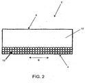
- FIG. 2 Depicted in FIG. 2 is a cross section through the thickness of a belt 2 constructed in accordance with one embodiment of the instant invention, as indicated by line A-A in FIG. 1 .
- the CD direction of the belt is indicated by arrow 8.
- Adjacent to the bottom surface 4 of the belt 2 are one or more layers of elastic yarns or fibers 10.
- the elastic yarns or fibers 10 are packed very tightly. This tight packing of the elastic yarns or fibers ensures that the belt 2 will not substantially shrink in width in the CD direction when it elongates in the MD direction while in use on a textile manufacturing machine.
- a silicone rubber layer 12 On top of the elastic yarns or fibers 10, adjacent to the outer surface 6 of the belt 2, is a silicone rubber layer 12.
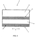
- FIGS. 3 and 4 depict cross-sections through the thickness of a belt 2, as indicated by line A-A in FIG. 1 constructed according to additional embodiments of the instant invention.
- FIG. 3 one or more layers of elastic yarns or fibers 10 are sandwiched between silicone rubber layers 12.
- FIG. 4 depicts a belt having a plurality of elastic yarn or fiber layers 10 that alternate with a plurality of silicone rubber layers 12.
- an elastic fiber or yam layer 10 is adjacent to the bottom surface 4 of the belt 2 and a silicone rubber layer 12 is adjacent to the outer surface 6 of the belt 2.
- a rubber belt constructed in accordance with the instant invention may have numerous configurations for the elastic yarn or fiber layers 10 and the silicone rubber layers 12.
Abstract
Description
- The instant invention relates generally to the production of textiles. More specifically, the instant invention relates to a textile machine belt that is used in the textile finishing process.
- Depending on the circumstances, circular knit fabrics may be required to undergo successive processing operations during the preparation, dyeing, finishing and making-up thereof both in tubular form, as they descend from the circular knitting machine, and in open form, obtained by cutting the tubular fabric along one of its side edges. Generally, before undergoing wet treatments such as, for example dyeing, depending on the type or types of fiber which form the fabric, the fabric is subjected to a heat setting operation. In particular, heat setting is performed on fabrics composed of or partly containing synthetic fibers, such as thermoplastic fibers. The aim of heat setting is to fix the dimensions and the flat state of the surfaces of the fabric thereby providing the fabric with stability. Heat setting a fabric also eliminates permanent creases or distortions that occur during the course of processing in bleaching and dyeing machines.
- With the currently available heat setting machines, it is not possible to differentiate between the processing of fabrics with an orthogonal pattern, i.e. of the weft/warp type, and the processing of knitted fabrics in general. This results in an increase in the duration of the processing cycle due to cutting and opening of the tubular fabric for heat setting and, sometimes, re-stitching of the fabric in a tubular form for the bleaching/dyeing operation, followed by reopening for the finishing and making-up operation. Moreover, these machines are unable to perform the heat setting of circular knitted fabrics, which must be completely processed in tubular form either for technical reasons, cost-related reasons or because of market requirements.
- Processing of fabrics in tubular form without heat setting results in considerable risks from the point of view of quality and is only performed in exceptional cases. In the past, various attempts have been made to develop specific machines for heat setting fabrics in tubular form. However, the results obtained have been somewhat unsatisfactory. The known machines are characterized essentially by the method of conveying and guiding the tubular fabric and by the system for transferring heat to the fabric.
- In some machines, the tubular fabric is guided by means of a flat expansion device and is fed in a flattened form between the surface of a heated steel cylinder and an endless felt belt. The main drawbacks of these machines include the squashing of the side edges of the tubular fabric and a non-uniform heat exchange on its two surfaces. In other machines, the tubular fabric is guided by means of a flat expansion device which accompanies it in a flattened form through a horizontal or vertical chamber until it emerges therefrom. Inside the chamber, the two surfaces of the tubular fabric are acted on by flows of hot air. The heat exchange on the two surfaces of the fabric, however, is inadequate.
- In a new textile manufacturing process, an elastic belt having a definite length is used. During the manufacturing process, in a section of the machine used to heat set the textile or cloth being produced, the definite length elastic belt elongates from 50 to 70% of its original length. Currently, rubber and nitrile rubber belts reinforced with yarns or fibers having a standard elasticity are used in the new manufacturing process. In addition, belts made only with rubber have also been used. These types of belts, however, have exhibited a short service life when used in the new textile manufacturing process. The service life of these prior belts are shortened even more when subjected to the elevated temperatures in the heat setting sections of the textile manufacturing machine. Therefore, the temperatures that can be used in the manufacturing process are limited. Furthermore, the prior rubber belts experience excessive shortening in width in the cross-machine (CD) direction when elongated in the machine (MD) direction, which creates problems in the manufacturing process.
- Attempts have been made to solve the problems associated with prior belts by utilizing belts coated with an elastic material. These attempts, however, have been unsuccessful since delamination of the coating from the belt occurs.
- Accordingly, a need exists for a rubber belt that does not substantially shrink in width in the CD direction while it elongates from 50 to 70% of its original length in the MD direction. Furthermore, a reinforced rubber belt is needed that has a low risk of delamination between the rubber portion and the reinforcing portion of the belt while elongating in the MD direction. The instant invention is directed to overcoming these shortcomings associated with prior art belts.
GB-A-1 030 354 GB-A-1 088 066 - It is therefore a principal object of the invention to provide a textile machine rubber belt that is capable of being used in a new textile manufacturing process.
- It is a further object of the invention to provide a rubber belt that is capable of being used at elevated temperatures such as those experienced in a heat setting section of a textile manufacturing machine.
- Yet another object of the invention is to provide a rubber belt that is capable of elongating from 50 to 70% of its original length.
- A further obj ect of the invention is to provide a rubber belt that does not substantially shrink in the CD direction while it elongates in the MD direction.
- A still further object of the invention is to provide a rubber belt that resists delamination when elongating.
- Yet another objective of the invention is to provide a rubber belt that is capable of being used to produce a variety of textiles.
- A still further objective of the instant invention is to provide a rubber belt that is more durable, resulting in an increased service life.
- These and other objects and advantages are provided by the instant invention. In this regard, the instant invention is directed to a machine belt that is used to manufacture textiles. The instant belt is a rubber belt comprising at least one layer of tightly packed elastic yarns or fibers and a layer of silicone rubber. The elastic yarns or fibers are tightly packed in order to allow the belt to elongate in length in the MD direction while the belt's width in the CD direction remains substantially unchanged.
- In addition, the instant invention is directed to a method of manufacturing a textile machine rubber belt. The method comprises wrapping one or more elastic yarns or fibers onto a mandrel or around two substantially parallel rolls, wherein the one or more elastic yarns or fibers form one or more layers on the mandrel or the substantially parallel rolls. Once the elastic yarns or fibers are wrapped onto the mandrel or around the substantially parallel rolls, a liquid high viscosity silicone rubber is added on top of the one or more yarns layers. After the silicone rubber is added, the mandrel or the two substantially parallel rolls and the added silicone rubber, are heated in order to polymerize the silicone rubber.
- The various features of novelty which characterize the invention are pointed out in particularity in the claims annexed to and forming a part of this disclosure. For a better understanding of the invention, its operating advantages and specific objects attained by its uses, reference is made to the accompanying descriptive matter in which preferred embodiments of the invention are illustrated in the accompanying drawings in which corresponding components are identified by the same reference numerals.
- The following detailed description, given by way of example and not intended to limit the present invention solely thereto, will best be appreciated in conjunction with the accompanying drawings, wherein like reference numerals denote like elements and parts, in which:
-
FIG. 1 is a perspective view of a belt of the instant invention; -
FIG. 2 is a cross-sectional view of a belt taken as indicated by line A-A inFIG. 1 , according to one embodiment of the instant invention; -
FIG. 3 is a cross-sectional view of a belt taken as indicated by line A-A inFIG. 1 , according to another embodiment of the instant invention; and -
FIG. 4 is a cross-sectional view of a belt taken as indicated by line A-A inFIG. 1 , according to a further embodiment of the instant invention;. - The instant invention will now be described more fully hereinafter with reference to the accompanying drawings, in which preferred embodiments of the invention are shown. This invention may, however, be embodied in many different forms and should not be construed as limited to the illustrated embodiments set forth herein. Rather, these illustrated embodiments are provided so that this disclosure will be thorough and complete, and will fully convey the scope of the invention to those skilled in the art. In the following description, like reference characters designate like or corresponding parts throughout the figures.
- The instant invention relates to a textile machine silicone rubber belt that is reinforced with a structure comprised of elastic yarns or fibers. As used herein, an elastic yarn or fiber is a yam or fiber with an elongation at its breaking point of between 40 and 400% of its original length.
- Currently, there exist rubber belts made with natural or synthetic rubbers, which are reinforced with yarns or fibers having a standard elasticity. Belts made only with natural, synthetic and silicone rubber also exist. The natural and synthetic rubber belts, however, have good elasticity but they also have low chemical and thermal resistances. On the contrary, belts made only of silicone rubber have very good thermal and chemical resistances but poor mechanical properties. Since a belt having good thermal and chemical resistances along with good mechanical properties is desired, a reinforced silicone rubber belt is needed and provided by the instant invention.
- In an attempt to construct the desired reinforced rubber belt, a coating system was used. That is, an endless base fabric was constructed and coated with silicone rubber. In order to have good mechanical properties, the belt was constructed to have a double or triple layer base. This type of belt, however, created a structure having a high risk of delamination between the woven base and the silicone rubber coating, especially when the belt was stretched to a high elongation.
- The instant invention solves the problems associated with prior coated belts by providing a rubber belt that is more elastic and more durable than prior belts. In a preferred embodiment, the instant invention is constructed by wrapping elastic yarns or fibers constructed from materials, such as but not limited to, natural rubber, LYCRA® and ELASTAN®, onto a cylinder or mandrel. The circumference of the mandrel should be close to the overall length of the elastic belt being constructed. At least one layer of elastic yarns or fibers are wrapped onto the mandrel. The number of layers of elastic yarns depend on the desired resistance of the belt to elongation. A single layer or a plurality of elastic yam or fiber layers can be achieved by wrapping a single elastic yam or fiber onto the mandrel in a continuous manner such that a single layer or a plurality of layers are formed with the elastic yarns or fibers in each layer tightly packed adjacent to one another. In addition, a plurality of elastic yarns or fibers can be wrapped onto the mandrel to form the one or more layers of tightly packed elastic yarns or fibers.
- Once the elastic yarns or fibers are wrapped onto or applied to the mandrel, a high viscosity silicone rubber is added on top of the elastic yam or fiber layers. Silicone rubber is added in order to attain the belt's required thickness and to provide a textile contacting surface. The textile contacting surface may be designed to impart a smooth or a textured finish to the textile being formed thereon.
- The elastic yarns or fibers are specially treated with a tie coat or adhesion promoter in order to assure an excellent adhesion between the elastic yarns or fibers and the silicone rubber coating, thereby reducing the risk of belt delamination upon elongation. Adhesion between the yarns and the silicone rubber coating can also be increased by using twisted, multifilament yarns.
- When the addition of the silicone rubber is completed, the mandrel is heated in order to polymerize the silicone rubber. A rubber belt constructed in this manner does not substantially shrink in width in the CD direction while it elongates in the MD direction and is capable of elongating from 50 to 70% of its original length in the MD direction. The completed belt may be used in textile finishing applications to finish, for example, textiles constructed of cotton, wool, synthetic fibers as well as blends of different fibers.
- An alternative method for constructing the instant belt is similar to the preferred method in all aspects except that instead of constructing the belt on a mandrel, the instant belt is constructed using two substantially parallel rolls that are spaced apart from one another. The distance between the two substantially parallel rolls corresponds to the overall length of the completed belt. With this method, the elastic yarns or fibers are wrapped around the two substantially parallel rolls. Once the elastic yarns are wrapped onto the rolls, construction of the belt proceeds as detailed above for the mandrel.
- A perspective view of an elastic silicone rubber belt of the instant invention is provided in
FIG. 1 . Thebelt 2 has an inner orbottom surface 4 and an outer orupper surface 6. Theouter surface 6 is the textile contacting surface. Theinner surface 4 of thebelt 2 is in contact with the steel cylinders of the textile manufacturing machine. - Depicted in
FIG. 2 is a cross section through the thickness of abelt 2 constructed in accordance with one embodiment of the instant invention, as indicated by line A-A inFIG. 1 . The CD direction of the belt is indicated byarrow 8. Adjacent to thebottom surface 4 of thebelt 2 are one or more layers of elastic yarns orfibers 10. As can be seen inFIG. 2 , the elastic yarns orfibers 10 are packed very tightly. This tight packing of the elastic yarns or fibers ensures that thebelt 2 will not substantially shrink in width in the CD direction when it elongates in the MD direction while in use on a textile manufacturing machine. On top of the elastic yarns orfibers 10, adjacent to theouter surface 6 of thebelt 2, is asilicone rubber layer 12. -
FIGS. 3 and4 depict cross-sections through the thickness of abelt 2, as indicated by line A-A inFIG. 1 constructed according to additional embodiments of the instant invention. As shown inFIG. 3 , one or more layers of elastic yarns orfibers 10 are sandwiched between silicone rubber layers 12.FIG. 4 depicts a belt having a plurality of elastic yarn or fiber layers 10 that alternate with a plurality of silicone rubber layers 12. In this configuration, an elastic fiber oryam layer 10 is adjacent to thebottom surface 4 of thebelt 2 and asilicone rubber layer 12 is adjacent to theouter surface 6 of thebelt 2. As will be apparent to a skilled artisan, a rubber belt constructed in accordance with the instant invention, may have numerous configurations for the elastic yarn or fiber layers 10 and the silicone rubber layers 12. - Although a preferred embodiment of the present invention and modifications thereof have been described in detail herein, it is to be understood that this invention is not limited to this precise embodiment and modifications, and that other modifications and variations may be effected by one skilled in the art without departing from the scope of the invention as defined by the appended claims. The use of the instant belt in accordance with the invention is not limited to machines for rendering textiles shrinkproof, in other words, the instant belt can be used anywhere where the requirements mentioned above are placed on the quality and serviceable life of the belt.
Claims (21)
- A textile machine rubber belt (2) having at least one layer of silicone rubber (12), characterized by comprising at least one layer having a plurality of tightly packed elastic yarns or fibers (10) extending in the machine direction.
- The rubber belt as claimed in claim 1, wherein said at least one layer of tightly packed elastic yarns or fibers (10) is constructed using a single elastic yarn or fiber (10) that is wrapped onto a mandrel in a continuous manner.
- The rubber belt as claimed in claim 1, wherein said at least one layer of tightly packed elastic yarns or fibers (10) is constructed using a plurality of elastic yarns or fibers.
- The rubber belt as claimed in claim 1, wherein said elastic yarns or fibers (10) have an elongation at a breaking point between 40 and 400% of their original length.
- The rubber belt as claimed in claim 1, wherein said rubber belt (2) elongates in the machine direction from 50 to 70% of its original length.
- The rubber belt as claimed in claim 5, wherein a width of said elongated rubber belt (2) remains substantially unchanged in the cross machine direction when said belt (2) is elongated in said machine direction.
- The rubber belt as claimed in claim 1, wherein said elastic yarns or fibers (10) are treated with a tie coat or adhesion promoter.
- The rubber belt as claimed in claim 1, wherein said elastic yarns or fibers (10) are twistedmonofilament yarns or fibers.
- The rubber belt as claimed in claim 1, wherein said elastic yarns or fibers (10) are formed of an elastic material.
- The rubber belt as claimed in claim 9, wherein said elasticmaterial is selected from the group consisting of natural rubber, nitrile rubber, silicone rubber, LYCRA(R) and ELASTAN(R).
- A method of manufacturing a textile machine rubber belt (2), characterized by comprising the steps of:wrapping one or more elastic yarns or fibers (10) onto a mandrel in the machine direction, wherein said one or more elastic yarns or fibers (10) form one or more layers on said mandrel;adding a liquid high viscosity silicone rubber (12) ontop of said one or more layers; andheating said mandrel in order to polymerize said silicone rubber (12).
- The method as claimed in claim 11, wherein said elastic yarns or fibers (10) have an elongation at a breaking point between 40 and 400% of their original length.
- The method as claimed in claim 11, wherein said rubber belt (2) elongates in the machine direction from 50 to 70% of its original length.
- The method as claimed in claim 13, wherein a width of said elongated rubber belt (2) remains substantially unchanged in the cross machine direction when said belt (2) is elongated in said machine direction.
- The method as claimed in claim 11 further comprising the step of treating said elastic yarns or fibers (10) with a tie coat or adhesion promoter.
- The method as claimed in claim 11, wherein said elasticyarnsorfibers (10) aretwistedmonofilamentyarns or fibers.
- The method as claimed in claim 11, wherein said elastic yarns or fibers (10) are formed of an elastic material.
- The method as claimed in claim 17, wherein said elastic material is selected from the group consisting of natural rubber, LYCRA(R) and ELASTAN(R).
- A method of manufacturing a textile machine rubber belt (2) comprising the steps of:wrapping one or more elastic yarns or fibers (10) around two substantially parallel rolls spaced a distance apart from each other in the machine direction, wherein said one or more elastic yarns or fibers (10) form one or more layers on said two substantially parallel rolls;adding a liquid high viscosity silicone rubber (12) on top of said one or more layers; andheating said two substantially parallel rolls and said added liquid silicone rubber (12) in order to polymerize said silicone rubber (12).
- The method as claimed in claim 19, wherein said elastic yarns or fibers (10) are formed of an elastic material.
- The method as claimed in claim 11 or 19, wherein said silicone rubber (12) encompasses said one or more elastic yarns or fibers (10).
Priority Applications (1)
| Application Number | Priority Date | Filing Date | Title |
|---|---|---|---|
| PL06848036T PL1974081T3 (en) | 2005-12-29 | 2006-12-21 | Elastic silicone rubber belt |
Applications Claiming Priority (2)
| Application Number | Priority Date | Filing Date | Title |
|---|---|---|---|
| US11/320,989 US9222208B2 (en) | 2005-12-29 | 2005-12-29 | Elastic silicone rubber belt |
| PCT/US2006/049038 WO2007079029A2 (en) | 2005-12-29 | 2006-12-21 | Elastic silicone rubber belt |
Publications (2)
| Publication Number | Publication Date |
|---|---|
| EP1974081A2 EP1974081A2 (en) | 2008-10-01 |
| EP1974081B1 true EP1974081B1 (en) | 2010-04-14 |
Family
ID=38107991
Family Applications (1)
| Application Number | Title | Priority Date | Filing Date |
|---|---|---|---|
| EP06848036A Active EP1974081B1 (en) | 2005-12-29 | 2006-12-21 | Elastic silicone rubber belt |
Country Status (18)
| Country | Link |
|---|---|
| US (1) | US9222208B2 (en) |
| EP (1) | EP1974081B1 (en) |
| JP (1) | JP5033812B2 (en) |
| KR (1) | KR101383026B1 (en) |
| CN (1) | CN101346504B (en) |
| AT (1) | ATE464418T1 (en) |
| AU (1) | AU2006332887A1 (en) |
| BR (1) | BRPI0620746B1 (en) |
| CA (1) | CA2632474C (en) |
| DE (1) | DE602006013716D1 (en) |
| ES (1) | ES2345360T3 (en) |
| NO (1) | NO20083312L (en) |
| PL (1) | PL1974081T3 (en) |
| PT (1) | PT1974081E (en) |
| RU (1) | RU2425185C2 (en) |
| TW (1) | TWI428487B (en) |
| WO (1) | WO2007079029A2 (en) |
| ZA (1) | ZA200804819B (en) |
Families Citing this family (5)
| Publication number | Priority date | Publication date | Assignee | Title |
|---|---|---|---|---|
| JP2012530195A (en) * | 2009-06-12 | 2012-11-29 | フェデラル−モーグル パワートレイン インコーポレイテッド | Woven sleeve with high temperature wear resistant coating and method of assembly, construction and curing thereof |
| DE202013000165U1 (en) * | 2013-01-09 | 2013-04-02 | Hübner GmbH | Bellows a transition of an articulated vehicle and articulated vehicle of public transport with such a bellows |
| CN105179439A (en) * | 2015-09-29 | 2015-12-23 | 上海和为科技有限公司 | Weft-free ring |
| CN110565310A (en) * | 2019-08-30 | 2019-12-13 | 安徽省通信产业服务有限公司 | Anti-aging method for insulating adhesive tape |
| CN110747631B (en) * | 2019-10-12 | 2022-03-01 | 陕西科技大学 | Preparation method of flexible and stretchable silicon rubber-based wearable strain sensing fiber |
Family Cites Families (35)
| Publication number | Priority date | Publication date | Assignee | Title |
|---|---|---|---|---|
| US2021975A (en) | 1931-02-10 | 1935-11-26 | Cluett Peabody & Co Inc | Method of and means for treating woven and the like fabrics and yarns |
| GB1030354A (en) | 1964-02-14 | 1966-05-18 | James Dawson & Son Ltd | An improved endless conveyor band and a method for the production thereof |
| NL6511189A (en) | 1964-12-02 | 1966-06-03 | ||
| US3469001A (en) * | 1965-10-08 | 1969-09-23 | Du Pont | Process for making polyester cord for no-reset v-belts |
| US3792621A (en) * | 1972-10-11 | 1974-02-19 | T Smith | Drive belt |
| IT973167B (en) * | 1972-12-29 | 1974-06-10 | Pirelli | ANULAR ELEMENTS ACCESSORIES FOR TES SILE INDUSTRY MACHINERY AND MANUFACTURING PROCESS RELATED CAUTION |
| US4183986A (en) * | 1978-12-14 | 1980-01-15 | Timex Corporation | Method for making straps |
| JPS5842444U (en) * | 1981-09-17 | 1983-03-22 | 三ツ星ベルト株式会社 | V-belt for power transmission |
| JPS58118332U (en) | 1982-02-05 | 1983-08-12 | 三ツ星ベルト株式会社 | Power transmission belt |
| US4674622A (en) * | 1985-08-14 | 1987-06-23 | Bridgestone Corporation | Conveyor belt |
| EP0280175B1 (en) * | 1987-02-27 | 1993-05-05 | Nitta Industries Corporation | Process for producing endless belt |
| US4987030A (en) | 1987-10-07 | 1991-01-22 | Toray Industries, Inc. | High-tenacity conjugated fiber and process for preparation thereof |
| US5261473A (en) | 1988-09-28 | 1993-11-16 | Compagnie Generale Des Etablissements Michelin-Michelin & Cie | Assembly of concentric layers of filaments |
| JP3007371B2 (en) | 1990-02-23 | 2000-02-07 | バンドー化学株式会社 | Fiber reinforced rubber products |
| US5233733A (en) | 1990-04-12 | 1993-08-10 | Rollin S.A. | Sheet material shrinkage apparatus |
| US5208087A (en) * | 1991-10-08 | 1993-05-04 | Albany International Corp. | Spiral construction for a long nip press belt |
| US5171389A (en) * | 1991-11-08 | 1992-12-15 | Albany International Corp. | Spiral construction of grooved long nip press |
| US5744237A (en) * | 1993-02-19 | 1998-04-28 | Hoechst Celanese Corporation | Heterofilaments for cord reinforcement in rubber goods |
| US5731059A (en) * | 1993-04-07 | 1998-03-24 | Wangner Systems Corporation | Dryer fabric having an abrasion resistant edge |
| US5360379A (en) * | 1993-10-25 | 1994-11-01 | Alliedsignal Inc. | Packaging machinery belt with non-directional splice |
| US5846654A (en) * | 1995-06-02 | 1998-12-08 | Hercules Incorporated | High tenacity, high elongation polypropylene fibers, their manufacture, and use |
| JPH09109283A (en) * | 1995-10-13 | 1997-04-28 | Kureha Elastomer Kk | Endless rubber belt and its manufacture |
| JP3634952B2 (en) * | 1997-11-18 | 2005-03-30 | 株式会社金陽社 | Manufacturing method of transfer belt for electronic equipment |
| JPH11231699A (en) * | 1998-02-16 | 1999-08-27 | Kin Yosha Kk | Belt type fixing device |
| US6228448B1 (en) * | 1999-02-24 | 2001-05-08 | Day International, Inc. | Endless belt for use in digital imaging systems |
| JP3488397B2 (en) * | 1999-04-26 | 2004-01-19 | 市川毛織株式会社 | Shoe press belt and method of manufacturing the same |
| ATE317076T1 (en) * | 1999-11-12 | 2006-02-15 | Gates Corp | DRIVE BELT WITH OPEN MESH TEXTILE MATERIAL IN THE BACK FABRIC FOR IMPROVED RUBBER PERSONALITY |
| MXPA02005812A (en) * | 1999-11-12 | 2005-07-01 | Gates Corp | Power transmission belt with tubular knit overcord. |
| US6630223B2 (en) * | 2001-01-26 | 2003-10-07 | Albany International Corp. | Spirally wound shaped yarns for paper machine clothing and industrial belts |
| JP2003090376A (en) * | 2001-07-13 | 2003-03-28 | Toray Ind Inc | Impact energy absorbing member |
| WO2004072368A1 (en) | 2003-02-12 | 2004-08-26 | Huyck Austria Ges.M.B.H. | Fabric belt |
| DE10327027A1 (en) | 2003-06-16 | 2005-01-05 | Brückner Trockentechnik GmbH & Co. KG | Device for compacting textile webs |
| US7303656B2 (en) * | 2003-07-02 | 2007-12-04 | Albany International Corp. | Low permeability textile substrate for a two-sided coated product |
| DE102004021524A1 (en) * | 2004-05-03 | 2005-12-08 | Arntz Beteiligungs Gmbh & Co. Kg | Power transmission belt and method for its manufacture |
| EP1657340A1 (en) * | 2004-11-15 | 2006-05-17 | Sperotto Rimar S.R.L. | Apparatus and method for shrinking textile substrates |
-
2005
- 2005-12-29 US US11/320,989 patent/US9222208B2/en active Active
-
2006
- 2006-12-21 JP JP2008548652A patent/JP5033812B2/en not_active Expired - Fee Related
- 2006-12-21 PL PL06848036T patent/PL1974081T3/en unknown
- 2006-12-21 BR BRPI0620746A patent/BRPI0620746B1/en active IP Right Grant
- 2006-12-21 EP EP06848036A patent/EP1974081B1/en active Active
- 2006-12-21 DE DE602006013716T patent/DE602006013716D1/en active Active
- 2006-12-21 AU AU2006332887A patent/AU2006332887A1/en not_active Abandoned
- 2006-12-21 ZA ZA200804819A patent/ZA200804819B/en unknown
- 2006-12-21 CA CA2632474A patent/CA2632474C/en active Active
- 2006-12-21 ES ES06848036T patent/ES2345360T3/en active Active
- 2006-12-21 AT AT06848036T patent/ATE464418T1/en active
- 2006-12-21 PT PT06848036T patent/PT1974081E/en unknown
- 2006-12-21 CN CN2006800493394A patent/CN101346504B/en not_active Expired - Fee Related
- 2006-12-21 WO PCT/US2006/049038 patent/WO2007079029A2/en active Application Filing
- 2006-12-21 RU RU2008122348/05A patent/RU2425185C2/en active
- 2006-12-21 KR KR1020087018583A patent/KR101383026B1/en active IP Right Grant
- 2006-12-27 TW TW095149162A patent/TWI428487B/en not_active IP Right Cessation
-
2008
- 2008-07-28 NO NO20083312A patent/NO20083312L/en not_active Application Discontinuation
Also Published As
| Publication number | Publication date |
|---|---|
| ZA200804819B (en) | 2009-11-25 |
| DE602006013716D1 (en) | 2010-05-27 |
| KR20080081357A (en) | 2008-09-09 |
| PT1974081E (en) | 2010-07-06 |
| NO20083312L (en) | 2008-09-25 |
| CN101346504A (en) | 2009-01-14 |
| TW200736436A (en) | 2007-10-01 |
| US9222208B2 (en) | 2015-12-29 |
| WO2007079029A2 (en) | 2007-07-12 |
| JP2009522135A (en) | 2009-06-11 |
| BRPI0620746A2 (en) | 2011-11-22 |
| CN101346504B (en) | 2012-11-28 |
| EP1974081A2 (en) | 2008-10-01 |
| RU2008122348A (en) | 2010-02-10 |
| WO2007079029A3 (en) | 2007-08-23 |
| US20070155565A1 (en) | 2007-07-05 |
| CA2632474A1 (en) | 2007-07-12 |
| ES2345360T3 (en) | 2010-09-21 |
| CA2632474C (en) | 2014-08-12 |
| AU2006332887A1 (en) | 2007-07-12 |
| TWI428487B (en) | 2014-03-01 |
| RU2425185C2 (en) | 2011-07-27 |
| PL1974081T3 (en) | 2010-11-30 |
| ATE464418T1 (en) | 2010-04-15 |
| KR101383026B1 (en) | 2014-04-08 |
| BRPI0620746B1 (en) | 2016-10-11 |
| JP5033812B2 (en) | 2012-09-26 |
Similar Documents
| Publication | Publication Date | Title |
|---|---|---|
| KR102536089B1 (en) | Easily settable stretch fabrics including low-melt fiber | |
| JP7358237B2 (en) | Stretch knitted fabrics containing elastomeric fibers and polyester bicomponent filaments, garments made therefrom, and methods of manufacturing the same | |
| EP1974081B1 (en) | Elastic silicone rubber belt | |
| WO2018036876A1 (en) | Compression garment with multiple compression forces and method for forming the same | |
| RU2405872C2 (en) | Stitched with fibrous web fillet of heavy gauge with large elasticity | |
| JP2010531935A (en) | Textile manufacturing method | |
| US20030177749A1 (en) | Elastic air textured yarn and its manufacturing method | |
| US11028508B2 (en) | Method for making assembled textile products | |
| KR101102309B1 (en) | Method of manufacturing a resin coated knit by indirect coating type | |
| US20030005682A1 (en) | Elastic air textured yarn and its manufacturing method | |
| KR102451544B1 (en) | Process Of Producing Composite Yarn Having Excellent Color Depth And Drapability Property | |
| US3831200A (en) | Technique for eliminating pilling in shirt collars | |
| CN117731083A (en) | Auxetic fabric structure | |
| KR20100136054A (en) | Releasing fabric used in manufacturing a resin coated knit by indirect coating type |
Legal Events
| Date | Code | Title | Description |
|---|---|---|---|
| PUAI | Public reference made under article 153(3) epc to a published international application that has entered the european phase |
Free format text: ORIGINAL CODE: 0009012 |
|
| 17P | Request for examination filed |
Effective date: 20080620 |
|
| AK | Designated contracting states |
Kind code of ref document: A2 Designated state(s): AT BE BG CH CY CZ DE DK EE ES FI FR GB GR HU IE IS IT LI LT LU LV MC NL PL PT RO SE SI SK TR |
|
| 17Q | First examination report despatched |
Effective date: 20081027 |
|
| GRAP | Despatch of communication of intention to grant a patent |
Free format text: ORIGINAL CODE: EPIDOSNIGR1 |
|
| DAX | Request for extension of the european patent (deleted) | ||
| GRAS | Grant fee paid |
Free format text: ORIGINAL CODE: EPIDOSNIGR3 |
|
| GRAA | (expected) grant |
Free format text: ORIGINAL CODE: 0009210 |
|
| AK | Designated contracting states |
Kind code of ref document: B1 Designated state(s): AT BE BG CH CY CZ DE DK EE ES FI FR GB GR HU IE IS IT LI LT LU LV MC NL PL PT RO SE SI SK TR |
|
| REG | Reference to a national code |
Ref country code: GB Ref legal event code: FG4D |
|
| REG | Reference to a national code |
Ref country code: CH Ref legal event code: EP |
|
| REG | Reference to a national code |
Ref country code: IE Ref legal event code: FG4D |
|
| REF | Corresponds to: |
Ref document number: 602006013716 Country of ref document: DE Date of ref document: 20100527 Kind code of ref document: P |
|
| REG | Reference to a national code |
Ref country code: PT Ref legal event code: SC4A Free format text: AVAILABILITY OF NATIONAL TRANSLATION Effective date: 20100629 |
|
| REG | Reference to a national code |
Ref country code: SE Ref legal event code: TRGR |
|
| REG | Reference to a national code |
Ref country code: NL Ref legal event code: T3 |
|
| REG | Reference to a national code |
Ref country code: CH Ref legal event code: NV Representative=s name: MOINAS & SAVOYE SA |
|
| REG | Reference to a national code |
Ref country code: ES Ref legal event code: FG2A Ref document number: 2345360 Country of ref document: ES Kind code of ref document: T3 |
|
| LTIE | Lt: invalidation of european patent or patent extension |
Effective date: 20100414 |
|
| PG25 | Lapsed in a contracting state [announced via postgrant information from national office to epo] |
Ref country code: LT Free format text: LAPSE BECAUSE OF FAILURE TO SUBMIT A TRANSLATION OF THE DESCRIPTION OR TO PAY THE FEE WITHIN THE PRESCRIBED TIME-LIMIT Effective date: 20100414 |
|
| PG25 | Lapsed in a contracting state [announced via postgrant information from national office to epo] |
Ref country code: SI Free format text: LAPSE BECAUSE OF FAILURE TO SUBMIT A TRANSLATION OF THE DESCRIPTION OR TO PAY THE FEE WITHIN THE PRESCRIBED TIME-LIMIT Effective date: 20100414 Ref country code: LV Free format text: LAPSE BECAUSE OF FAILURE TO SUBMIT A TRANSLATION OF THE DESCRIPTION OR TO PAY THE FEE WITHIN THE PRESCRIBED TIME-LIMIT Effective date: 20100414 Ref country code: IS Free format text: LAPSE BECAUSE OF FAILURE TO SUBMIT A TRANSLATION OF THE DESCRIPTION OR TO PAY THE FEE WITHIN THE PRESCRIBED TIME-LIMIT Effective date: 20100814 |
|
| REG | Reference to a national code |
Ref country code: PL Ref legal event code: T3 |
|
| PG25 | Lapsed in a contracting state [announced via postgrant information from national office to epo] |
Ref country code: CY Free format text: LAPSE BECAUSE OF FAILURE TO SUBMIT A TRANSLATION OF THE DESCRIPTION OR TO PAY THE FEE WITHIN THE PRESCRIBED TIME-LIMIT Effective date: 20100602 |
|
| PG25 | Lapsed in a contracting state [announced via postgrant information from national office to epo] |
Ref country code: GR Free format text: LAPSE BECAUSE OF FAILURE TO SUBMIT A TRANSLATION OF THE DESCRIPTION OR TO PAY THE FEE WITHIN THE PRESCRIBED TIME-LIMIT Effective date: 20100715 Ref country code: EE Free format text: LAPSE BECAUSE OF FAILURE TO SUBMIT A TRANSLATION OF THE DESCRIPTION OR TO PAY THE FEE WITHIN THE PRESCRIBED TIME-LIMIT Effective date: 20100414 Ref country code: DK Free format text: LAPSE BECAUSE OF FAILURE TO SUBMIT A TRANSLATION OF THE DESCRIPTION OR TO PAY THE FEE WITHIN THE PRESCRIBED TIME-LIMIT Effective date: 20100414 |
|
| PLBE | No opposition filed within time limit |
Free format text: ORIGINAL CODE: 0009261 |
|
| STAA | Information on the status of an ep patent application or granted ep patent |
Free format text: STATUS: NO OPPOSITION FILED WITHIN TIME LIMIT |
|
| PG25 | Lapsed in a contracting state [announced via postgrant information from national office to epo] |
Ref country code: SK Free format text: LAPSE BECAUSE OF FAILURE TO SUBMIT A TRANSLATION OF THE DESCRIPTION OR TO PAY THE FEE WITHIN THE PRESCRIBED TIME-LIMIT Effective date: 20100414 Ref country code: RO Free format text: LAPSE BECAUSE OF FAILURE TO SUBMIT A TRANSLATION OF THE DESCRIPTION OR TO PAY THE FEE WITHIN THE PRESCRIBED TIME-LIMIT Effective date: 20100414 |
|
| 26N | No opposition filed |
Effective date: 20110117 |
|
| PGFP | Annual fee paid to national office [announced via postgrant information from national office to epo] |
Ref country code: GB Payment date: 20101229 Year of fee payment: 5 |
|
| PG25 | Lapsed in a contracting state [announced via postgrant information from national office to epo] |
Ref country code: MC Free format text: LAPSE BECAUSE OF NON-PAYMENT OF DUE FEES Effective date: 20101231 Ref country code: CZ Free format text: LAPSE BECAUSE OF NON-PAYMENT OF DUE FEES Effective date: 20101221 |
|
| REG | Reference to a national code |
Ref country code: PT Ref legal event code: MM4A Free format text: LAPSE DUE TO NON-PAYMENT OF FEES Effective date: 20110921 |
|
| PG25 | Lapsed in a contracting state [announced via postgrant information from national office to epo] |
Ref country code: IE Free format text: LAPSE BECAUSE OF NON-PAYMENT OF DUE FEES Effective date: 20101221 Ref country code: PT Free format text: LAPSE BECAUSE OF NON-PAYMENT OF DUE FEES Effective date: 20110921 |
|
| PGFP | Annual fee paid to national office [announced via postgrant information from national office to epo] |
Ref country code: SE Payment date: 20111229 Year of fee payment: 6 Ref country code: ES Payment date: 20111226 Year of fee payment: 6 |
|
| PGFP | Annual fee paid to national office [announced via postgrant information from national office to epo] |
Ref country code: NL Payment date: 20120103 Year of fee payment: 6 |
|
| PG25 | Lapsed in a contracting state [announced via postgrant information from national office to epo] |
Ref country code: PL Free format text: LAPSE BECAUSE OF NON-PAYMENT OF DUE FEES Effective date: 20101221 |
|
| PG25 | Lapsed in a contracting state [announced via postgrant information from national office to epo] |
Ref country code: LU Free format text: LAPSE BECAUSE OF NON-PAYMENT OF DUE FEES Effective date: 20101221 Ref country code: BG Free format text: LAPSE BECAUSE OF FAILURE TO SUBMIT A TRANSLATION OF THE DESCRIPTION OR TO PAY THE FEE WITHIN THE PRESCRIBED TIME-LIMIT Effective date: 20100414 Ref country code: HU Free format text: LAPSE BECAUSE OF FAILURE TO SUBMIT A TRANSLATION OF THE DESCRIPTION OR TO PAY THE FEE WITHIN THE PRESCRIBED TIME-LIMIT Effective date: 20101015 |
|
| PG25 | Lapsed in a contracting state [announced via postgrant information from national office to epo] |
Ref country code: TR Free format text: LAPSE BECAUSE OF FAILURE TO SUBMIT A TRANSLATION OF THE DESCRIPTION OR TO PAY THE FEE WITHIN THE PRESCRIBED TIME-LIMIT Effective date: 20100414 |
|
| REG | Reference to a national code |
Ref country code: PL Ref legal event code: LAPE |
|
| REG | Reference to a national code |
Ref country code: NL Ref legal event code: V1 Effective date: 20130701 |
|
| PG25 | Lapsed in a contracting state [announced via postgrant information from national office to epo] |
Ref country code: SE Free format text: LAPSE BECAUSE OF NON-PAYMENT OF DUE FEES Effective date: 20121222 |
|
| GBPC | Gb: european patent ceased through non-payment of renewal fee |
Effective date: 20121221 |
|
| PG25 | Lapsed in a contracting state [announced via postgrant information from national office to epo] |
Ref country code: BG Free format text: LAPSE BECAUSE OF FAILURE TO SUBMIT A TRANSLATION OF THE DESCRIPTION OR TO PAY THE FEE WITHIN THE PRESCRIBED TIME-LIMIT Effective date: 20100714 |
|
| PG25 | Lapsed in a contracting state [announced via postgrant information from national office to epo] |
Ref country code: NL Free format text: LAPSE BECAUSE OF NON-PAYMENT OF DUE FEES Effective date: 20130701 |
|
| PG25 | Lapsed in a contracting state [announced via postgrant information from national office to epo] |
Ref country code: GB Free format text: LAPSE BECAUSE OF NON-PAYMENT OF DUE FEES Effective date: 20121221 |
|
| REG | Reference to a national code |
Ref country code: ES Ref legal event code: FD2A Effective date: 20140602 |
|
| PG25 | Lapsed in a contracting state [announced via postgrant information from national office to epo] |
Ref country code: ES Free format text: LAPSE BECAUSE OF NON-PAYMENT OF DUE FEES Effective date: 20121222 |
|
| REG | Reference to a national code |
Ref country code: FR Ref legal event code: PLFP Year of fee payment: 10 |
|
| REG | Reference to a national code |
Ref country code: CH Ref legal event code: PFA Owner name: ALBANY INTERNATIONAL CORP., US Free format text: FORMER OWNER: ALBANY INTERNATIONAL CORP., US |
|
| REG | Reference to a national code |
Ref country code: FR Ref legal event code: PLFP Year of fee payment: 11 |
|
| PG25 | Lapsed in a contracting state [announced via postgrant information from national office to epo] |
Ref country code: IT Free format text: LAPSE BECAUSE OF NON-PAYMENT OF DUE FEES Effective date: 20151221 |
|
| PG25 | Lapsed in a contracting state [announced via postgrant information from national office to epo] |
Ref country code: IT Free format text: LAPSE BECAUSE OF NON-PAYMENT OF DUE FEES Effective date: 20151221 |
|
| PGRI | Patent reinstated in contracting state [announced from national office to epo] |
Ref country code: IT Effective date: 20170710 |
|
| REG | Reference to a national code |
Ref country code: FR Ref legal event code: PLFP Year of fee payment: 12 |
|
| PGFP | Annual fee paid to national office [announced via postgrant information from national office to epo] |
Ref country code: AT Payment date: 20181204 Year of fee payment: 13 |
|
| PGFP | Annual fee paid to national office [announced via postgrant information from national office to epo] |
Ref country code: BE Payment date: 20191227 Year of fee payment: 14 |
|
| PGFP | Annual fee paid to national office [announced via postgrant information from national office to epo] |
Ref country code: CH Payment date: 20191231 Year of fee payment: 14 |
|
| REG | Reference to a national code |
Ref country code: AT Ref legal event code: MM01 Ref document number: 464418 Country of ref document: AT Kind code of ref document: T Effective date: 20191221 |
|
| PG25 | Lapsed in a contracting state [announced via postgrant information from national office to epo] |
Ref country code: AT Free format text: LAPSE BECAUSE OF NON-PAYMENT OF DUE FEES Effective date: 20191221 |
|
| REG | Reference to a national code |
Ref country code: CH Ref legal event code: PL |
|
| REG | Reference to a national code |
Ref country code: BE Ref legal event code: MM Effective date: 20201231 |
|
| PG25 | Lapsed in a contracting state [announced via postgrant information from national office to epo] |
Ref country code: LI Free format text: LAPSE BECAUSE OF NON-PAYMENT OF DUE FEES Effective date: 20201231 Ref country code: CH Free format text: LAPSE BECAUSE OF NON-PAYMENT OF DUE FEES Effective date: 20201231 |
|
| PG25 | Lapsed in a contracting state [announced via postgrant information from national office to epo] |
Ref country code: BE Free format text: LAPSE BECAUSE OF NON-PAYMENT OF DUE FEES Effective date: 20201231 |
|
| P01 | Opt-out of the competence of the unified patent court (upc) registered |
Effective date: 20230613 |
|
| REG | Reference to a national code |
Ref country code: DE Ref legal event code: R082 Ref document number: 602006013716 Country of ref document: DE Representative=s name: SONNENBERG HARRISON PARTNERSCHAFT MBB PATENT- , DE |
|
| PGFP | Annual fee paid to national office [announced via postgrant information from national office to epo] |
Ref country code: IT Payment date: 20231220 Year of fee payment: 18 Ref country code: FR Payment date: 20231227 Year of fee payment: 18 Ref country code: FI Payment date: 20231227 Year of fee payment: 18 |
|
| PGFP | Annual fee paid to national office [announced via postgrant information from national office to epo] |
Ref country code: DE Payment date: 20231229 Year of fee payment: 18 |