EP1973743B1 - Verfahren, flüssigkeitsversorgungseinheit und messvorrichtung für eine füllstandsanzeige - Google Patents
Verfahren, flüssigkeitsversorgungseinheit und messvorrichtung für eine füllstandsanzeige Download PDFInfo
- Publication number
- EP1973743B1 EP1973743B1 EP07711332A EP07711332A EP1973743B1 EP 1973743 B1 EP1973743 B1 EP 1973743B1 EP 07711332 A EP07711332 A EP 07711332A EP 07711332 A EP07711332 A EP 07711332A EP 1973743 B1 EP1973743 B1 EP 1973743B1
- Authority
- EP
- European Patent Office
- Prior art keywords
- liquid
- sensor
- chamber
- supplying unit
- measuring
- Prior art date
- Legal status (The legal status is an assumption and is not a legal conclusion. Google has not performed a legal analysis and makes no representation as to the accuracy of the status listed.)
- Active
Links
Images

Classifications
-
- G—PHYSICS
- G01—MEASURING; TESTING
- G01F—MEASURING VOLUME, VOLUME FLOW, MASS FLOW OR LIQUID LEVEL; METERING BY VOLUME
- G01F23/00—Indicating or measuring liquid level or level of fluent solid material, e.g. indicating in terms of volume or indicating by means of an alarm
- G01F23/22—Indicating or measuring liquid level or level of fluent solid material, e.g. indicating in terms of volume or indicating by means of an alarm by measuring physical variables, other than linear dimensions, pressure or weight, dependent on the level to be measured, e.g. by difference of heat transfer of steam or water
- G01F23/26—Indicating or measuring liquid level or level of fluent solid material, e.g. indicating in terms of volume or indicating by means of an alarm by measuring physical variables, other than linear dimensions, pressure or weight, dependent on the level to be measured, e.g. by difference of heat transfer of steam or water by measuring variations of capacity or inductance of capacitors or inductors arising from the presence of liquid or fluent solid material in the electric or electromagnetic fields
-
- B—PERFORMING OPERATIONS; TRANSPORTING
- B41—PRINTING; LINING MACHINES; TYPEWRITERS; STAMPS
- B41J—TYPEWRITERS; SELECTIVE PRINTING MECHANISMS, i.e. MECHANISMS PRINTING OTHERWISE THAN FROM A FORME; CORRECTION OF TYPOGRAPHICAL ERRORS
- B41J2/00—Typewriters or selective printing mechanisms characterised by the printing or marking process for which they are designed
- B41J2/005—Typewriters or selective printing mechanisms characterised by the printing or marking process for which they are designed characterised by bringing liquid or particles selectively into contact with a printing material
- B41J2/01—Ink jet
- B41J2/17—Ink jet characterised by ink handling
- B41J2/175—Ink supply systems ; Circuit parts therefor
- B41J2/17503—Ink cartridges
- B41J2/17506—Refilling of the cartridge
- B41J2/17509—Whilst mounted in the printer
-
- B—PERFORMING OPERATIONS; TRANSPORTING
- B41—PRINTING; LINING MACHINES; TYPEWRITERS; STAMPS
- B41J—TYPEWRITERS; SELECTIVE PRINTING MECHANISMS, i.e. MECHANISMS PRINTING OTHERWISE THAN FROM A FORME; CORRECTION OF TYPOGRAPHICAL ERRORS
- B41J2/00—Typewriters or selective printing mechanisms characterised by the printing or marking process for which they are designed
- B41J2/005—Typewriters or selective printing mechanisms characterised by the printing or marking process for which they are designed characterised by bringing liquid or particles selectively into contact with a printing material
- B41J2/01—Ink jet
- B41J2/17—Ink jet characterised by ink handling
- B41J2/175—Ink supply systems ; Circuit parts therefor
- B41J2/17503—Ink cartridges
- B41J2/17513—Inner structure
-
- B—PERFORMING OPERATIONS; TRANSPORTING
- B41—PRINTING; LINING MACHINES; TYPEWRITERS; STAMPS
- B41J—TYPEWRITERS; SELECTIVE PRINTING MECHANISMS, i.e. MECHANISMS PRINTING OTHERWISE THAN FROM A FORME; CORRECTION OF TYPOGRAPHICAL ERRORS
- B41J2/00—Typewriters or selective printing mechanisms characterised by the printing or marking process for which they are designed
- B41J2/005—Typewriters or selective printing mechanisms characterised by the printing or marking process for which they are designed characterised by bringing liquid or particles selectively into contact with a printing material
- B41J2/01—Ink jet
- B41J2/17—Ink jet characterised by ink handling
- B41J2/175—Ink supply systems ; Circuit parts therefor
- B41J2/17566—Ink level or ink residue control
Definitions
- the present invention relates generally to the field of printing machines, and more particularly to a method according to the features of the preamble of claim 1 and according to the features of the preamble of claim 5 to a liquid supply unit comprising a measuring device for an ink printer for indicating a filling level.
- Ink printers are characterized by the selective application of liquid, in particular an ink jet, to a recording material, wherein the ink printer is a matrix printer in which the production of an image on a surface of ink droplets is produced by a targeted launching or deflecting of small ink droplets.
- liquid in particular an ink jet
- the ink printer is a matrix printer in which the production of an image on a surface of ink droplets is produced by a targeted launching or deflecting of small ink droplets.
- the liquid supply unit consists in principle of a fluid pressure system, which supplies by means of a fluid device, a liquid from a reservoir of a printing device, wherein the printing device may be additionally equipped with a reservoir for the liquid.
- the printing device of a liquid supply unit requires a sufficient filling of the reservoir with liquid for proper function.
- surveillance of the Amount of liquid in the liquid supply unit by measuring a liquid level with sequence control.
- all devices are understood with which measured values or measurement signals are processed directly or indirectly. This can be, for example, a microprocessor.
- the EP 0 778 141 B1 describes an apparatus for detecting the ink blank for inkjet printers.
- the device monitors the level of ink in the ink supply to detect when the ink supply is nearly depleted.
- the measuring method for determining the ink supply or the ink supply in the ink reservoir is based on a optical detector, which monitors an actuator, which is connected to a complex mechanism.
- a disadvantage is that not directly the level is measured, but an ink blanking signal, which is due to a predetermined time, while the chamber of a pump has not expanded, is determined.
- a liquid jet gauge apparatus for ink jet printers consisting of a plurality of electrically conductive rods of various lengths which measure the level of liquid in a separate chamber of a container to contact the liquid ink contained therein.
- the rods are connected to an impedance network which provides a series of output signals representing the level of ink within the shielded chamber.
- the disadvantage of this measurement method is the size of the sensor and that no contactless measurement between the sensor and the medium takes place and a continuous level can not be determined.
- an ink jet printer which has a first ink chamber with a "capillary component".
- This first ink chamber is disposed within a second ink chamber.
- the second chamber is connected to a main tank via a lower slit valve by means of an "ink refill station”.
- the second ink chamber is connected via an upper slit valve by means of the "ink refill station” with an outlet hose and a connected pump. At the outlet port the outlet hose and the pump are connected.
- the measuring device is formed as follows: A rise and a low of the ink in the second chamber are detected by means of an upper prism and a lower prism and the prisms associated optical sensors. That measuring principle is based on the principle of total reflection.
- a contactless level detector that is located in a recovery reservoir.
- This level detector operates as a level indicator and is of the capacitive or Hall effect type, wherein the non-contact measurement is made through the wall of the recovery reservoir. The measurement is made to avoid overflow of the reservoir and consequently to detect the volume of ink contained in the reservoir. Disadvantage of this ink circuit is the voluminous size of the double-sided support block, whereby use in the question in question printing machines, especially the commercial ink printers, is not possible.
- the level detector is used only to avoid the malfunction of overflowing the reservoir.
- the invention is therefore based on the object
- the invention is described by a method for a printing machine with printing device for applying liquid to a recording material, with monitoring of the amount of liquid in a liquid supply unit by measuring the liquid level with sequence control.
- the method is characterized by Providing the printing device with a housing having a liquid inlet port and a liquid outlet port and a reservoir for the fluid and a printhead, Connecting a reservoir for the liquid at the inlet opening and a measuring device with a chamber at the outlet opening and Measuring the liquid level by the measuring device, which detects the presence of liquid at the outlet of the printing device by detecting a liquid level in the chamber of the measuring device.
- the invention is described by a liquid supply unit for a printing machine with a printing device for applying liquid to a recording material, with monitoring of the amount of liquid in a liquid supply unit by measuring the liquid level with sequence control.
- the liquid supply unit is characterized in that the printing device comprises a housing having a liquid inlet port and a liquid outlet port, and comprising a reservoir and a printhead, and the reservoir is connected to the inlet opening and a measuring device with a chamber which is connected to the outlet opening and the measuring device is suitable for measuring a level in the chamber and for controlling a fluid device.
- the measuring device advantageously consists of a sensor with integrated evaluation electronics, wherein the measurement of the liquid state in the supply unit is performed by a measuring device that detects the presence of a liquid already at the output of the printing device. Due to the immediate proximity of the measuring device to the printing device, the size of the liquid supply unit can be reduced.
- the measuring device comprises a sensor.
- the measuring method is performed by a capacitive sensor. The liquid is detected by a capacitive measuring method, wherein the fill level is detected by the capacitive method and converted into a further processable condition or information.
- the condition or information is based on the change of the electric field in the environment of active measuring zone of the sensor. According to this change, the sensor generates a signal, which is fed to the transmitter.
- the condition is generated as a signal by an evaluation electronics integrated in the sensor.
- the signal generated by the transmitter is supplied to a device control.
- the sensor essentially consists of an RC oscillator as transducer, a demodulator and an output stage.
- the level change of the liquid in the chamber of the measuring device ie in the active measuring zone of the capacitive sensor, causes a capacitance change of the capacitor, whereby the RC oscillator changes its oscillating frequency.
- This causes the oscillator downstream trigger stage tilts and the switching amplifier changes its output state. Due to the immediate vicinity of the transmitter on the sensor stray capacitances and disturbances of the connecting lines between the sensor element and the transmitter are excluded.
- the signal generated by the transmitter or the signal jump is supplied to a device control, which makes the switching on or off of a fluid device which is arranged between the reservoir and the printing device.
- the fluid device provides for the liquid level in the liquid supply unit and thus for the level of the liquid in the pressure and measuring device.
- the liquid from the reservoir is conveyed by means of the fluid device through a feed line into the printing device, while the liquid flows into the integrated reservoir of the printing device and fills it out slowly.
- the liquid level rises in the up-looking spout into the outlet chamber of the measuring device, which is mounted on the printing device.
- the sensor of the measuring device detects the presence of liquid in the outlet and ensures that the printing device is completely filled with liquid.
- the measuring device according to the invention is thus suitable as a level sensor for determining a liquid level in a liquid supply unit, wherein the liquid from a water- or solvent-based fluid with or without color particles, which in turn may be present as solutions or pigments.
- the measuring device for continuous level measurement for aggressive media can also be used in other areas of technology.
- the measuring device comprises the sensor.
- parts of the sensor consist of a conductor material, wherein an electrode and / or evaluation electronics are or are connected to the printed circuit board material.
- the sensor includes one or more planar elements.
- the element is substantially formed as a printed circuit board material with embedded in plastic interconnects.
- the senor is essentially formed of three flat elements.
- an electrode is accommodated in at least one element.
- the electrode is formed flat.
- the transmitter is connected to the power supply via at least one conductor to a connector.
- the transmitter is connected to at least one track for signal processing.
- the conductor track is guided at least to a contact element suitable for device control of a device.
- the electrode and the evaluation electronics are connected to one another via contact elements and via printed conductors on the printed circuit board material.
- the elements lie in the manner of a sandwich, wherein the central element forms the chamber through a recessed area.
- the measuring device is characterized in that the middle element is equipped with connecting and / or positioning elements for the outer elements.
- the outer element is two-sided and the other outer element is laminated on one side.
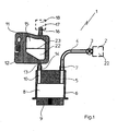
- Fig.1 shows in section a liquid supply unit 1 of an ink printer, not shown, for applying liquid 22 to a recording material.
- the liquid supply unit 1 comprises a storage container 2, which is connected via a fluid device 3 and optionally via a fluid line 4 to a pressure device 5.
- the pressure device 5 has a housing 6 with an inlet opening 7 and an outlet opening 10 and comprises a reservoir 8 with a print head 9 arranged underneath.
- a measuring device 11 with a feed flange 13 is connected to the outlet opening 10, which is connected to an inlet opening 14 via an inlet opening 14 the measuring device 1 arranged chamber 15 leads.
- the chamber 15 has on its housing on the opposite side to the inlet flange 13 arranged on an overflow flange 16 with an overflow opening 17. This is a valve 18 connected. In particular, it serves to protect against contamination for a liquid or ink present in the chamber 15.
- the measuring device 1 is designed by a preferably multi-part sensor 12, which according to the present embodiment is designed as a capacitive sensor 12 and at least partially consists of printed circuit board material. But it is also the use of all other known electrical sensors 12, for example. Inductive or optoelectric sensors, possible.
- the measuring device 1 is used to determine the liquid level in the reservoir 8 and for its targeted control.
- the measuring device 1 is connected in terms of control with the preferably designed as a pump fluid device 3.
- an evaluation 19 is mounted on an outer side of the sensor 12. It is connected to the power supply via printed conductors 27 with a connector plug 28 and for signal processing via printed conductors 24 with contact elements 21. To the contact elements 21, a device control (not shown) of the ink printer (not shown) can be connected via a signal line, not shown.
- the task of the measuring device 11 arranged in the liquid supply unit 1 is to detect the presence of liquid or to ensure that a reservoir 8 formed in the pressure device 5 is always filled with liquid 22.
- the sensor 12 is arranged at the outlet opening 10 of the printing device 5 and detects different liquid levels 23 in the chamber 15 formed outside the printing device 5 in the sensor 12 as a measured variable. The sensor 12 first generates measuring signals which correspond to the Evaluation electronics 19 are transmitted.
- the transmitter 19 If, for example, the liquid level 23 in the chamber 15, which results in a change in capacity, below the minimum level, the transmitter 19 generates a switch-on signal for switching on the fluid device 3.
- the switching can on the one hand via a direct connection between the fluid device. 3 and the transmitter 19 can be realized.
- the switch-on signal can be sent to a device controller (not shown) connected to the evaluation unit 19, which then switches on the fluid device 3.
- control lines between the device control and the fluid device or between the transmitter 19 and the fluid device are provided. On and off signals could also be sent via radio.
- the fluid device 3 promotes receipt of the turn-on signal from the reservoir 2 liquid 22 via the liquid line 4 and the pressure device 5 into the chamber 15 until the maximum level is exceeded.
- the evaluation electronics 19 detects the exceeding of the maximum fill level by comparing the electrical measurement signals supplied to it with the threshold value for the maximum fill level, wherein the electrical measurement signals in the present case correspond to sensed capacitance changes.
- the transmitter 19 If the excess of the maximum level detected by the transmitter 19, it sends itself a turn-off signal to the fluid device 3 and turns them off. Alternatively, this can be done analogously to the case described above via a connected to the transmitter 19 device control.
- the fluid level 23 drops until the minimum fluid level has been reached and the fluid device 3 is switched on by a device control or the evaluation electronics according to the method described above.
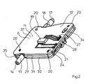
- FIG.2 is a perspective view of an advantageous embodiment of the measuring device 11 according to the invention with the sensor 12 in a miniaturized version of a multi-part housing 6 with connecting or positioning elements 20 shown.
- the sensor 12 can be connected via an inlet flange 13 with inlet opening 14 to an outlet opening 10 of the pressure device 5.
- an overflow flange 16 Opposite the narrow housing edge of the inlet flange 13, located on the same center line, located on the narrow housing edge an overflow flange 16 with an overflow opening 17.
- a valve 18 is mounted.
- the Fig.2 can be seen that the sensor 12 has at least one conductor 24 and at least one contact element 21 connected thereto, which establishes the electrical connection to arranged in the chamber 15 surface electrodes 30,33, and via electrical conductors 27 with the associated connector 28.
- the power supply can also be provided, for example, in the immediate vicinity of the evaluation 19 batteries provided.
- the transmitter 19 is advantageously arranged as a printed circuit on the outer surface 37 of the housing 6 of the sensor 12.
- the housing 6 is therefore at least partially formed by a conductor material. It is also conceivable, however, to use a microprocessor soldered onto the conductor material, for example, as evaluation electronics 19.
- the housing 6 of the sensor 12 is designed in several parts and in a broad sense rectangular, wherein the sensor 12 is preferably formed of three flat elements 29, 31, 32. Two of the elements 29,32 thereby form the two outer large-area housing halves, while the element 31 is arranged as a middle layer between the two elements 29,32 and forms with the two elements 29,32 the circumferential narrow housing edge 35.
- the two outer planar elements 29, 32 are designed as a carrier for the electrodes 30,33.
- the electrodes 30,33 are formed flat and arranged in a recess on the inner surface 36 of the elements 29,32 (see Figure 4 and Figure 5 ). Conceivable for fixing the electrodes 30,33 but also all other known connection options for metal surfaces. For example.
- the electrodes 30, 33 can be vapor-deposited onto the conductor material. Furthermore, as in the present embodiment of the invention, it is not mandatory that two electrodes 31, 32 be necessary for their function of sensing level change. An electrode 30, 33 is in principle sufficient for this purpose.
- the planar element 29 is additionally carrier of the evaluation electronics 19, the evaluation electronics 19 being fastened to the outer surface 37 of the element 29 facing away from the surface electrode 30.
- the housing 6 of the measuring device 11 is provided with an opening 34, preferably with a slot.
- the elongated hole 34 serves to receive a fastener (not shown), whereby the liquid supply unit 1 can be mounted in a printing device or an ink printer.
- Sandwiched between the two outer elements 29, 32 is the element 31, which occupies the central position of the sensor.
- the central surface element 31 is shown in perspective in FIG Figure 3 demonstrated.
- the surface element 31 is made in one piece and made of plastic by injection molding.
- the surface element 31 is provided with a chamber 15 forming the opening. It serves to receive liquid in the sensor 12, wherein the side walls of the chamber 15 are formed on the one hand by the inner contour 38 and on the other hand by the elements 29,32.
- the chamber 15 is a measuring space formed within the sensor 12, in which side walls are formed by the two planar electrodes 30, 33. Due to the size of the chamber 15 in the element 31 results in a frame-like contour 39, on the outer contour 40, the opposite flanges 13,16 are arranged with the openings 14,17 for access to the chamber 15, wherein the flange 13 for connection to the Pressure device 5 and the flange 16 are used to connect the valve 18. Furthermore, pins 41 are arranged on the surface element 31 as connection or positioning elements, and other connecting elements 20 are also conceivable. The pins 41 are located on both sides of the frame 39 and serve to fasten the surface elements 29,31,32.
- the pins 41 ensure the firm connection of the elements 29,31,32 with each other, the assembly by joining the elements 29,31,32 he follows.
- the joining of the elements 29,31,32 can also be done by the bonding technique of bonding, whereby the combination of the assembly of the elements 29,31,32 by gluing and pressing is possible.
- the elements 29,31,32 possibly also be welded without mechanical fasteners. However, at least one positioning aid should be provided.
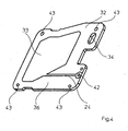
- Figure 4 shows in perspective view the surface element 32, which forms an outer element of the housing 6 of the sensor 12.
- the surface element 32 comprises an inner surface 36, on which the electrode 33 is arranged with the conductor track 24 and a bore 42, which serves to receive the contact element 21.
- the bore 42 may optionally be made with or without via. If no through-connection of the bore 42 is provided, the contacting of the conductor tracks 24 on the element 29 and the element 32 takes place with a contact rivet or a contact sleeve (not shown).
- the contact element 21 establishes the electrical connection with the evaluation electronics 19 arranged on the outer surface 37 of the surface element 29.
- the surface element 32 consists of printed circuit board material, whereby the sensor 12 can be inexpensively manufactured in printed circuit board technology with one-sided or two-sided lamination.
- the surface element 32 preferably consists of printed circuit board material with one-sided lamination for the surface electrode 33 lying on the inner surface 36 with associated conductor track 24.
- the surface element 32 includes, as the element 31 of the intermediate layer, an opening which is formed as a slot 34. Furthermore, they are relatively small Openings, preferably bores 43, for receiving the connecting or positioning elements 20 of the surface element 31 are provided.
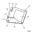
- the surface element 29 from the perspective view of Figure 5 Again, the inner surface 36 of the element 29 with the surface electrode 30 shown thereon with associated conductor 24 and the optionally with or without plated through hole 42 for receiving a contact element 21, which electrical connection to the transmitter 19 manufactures shown.
- the surface element 29 also essentially consists of printed circuit board material and is laminated on two sides. The surface element 29 is thus a carrier of the electrode 30 located on the inner surface 36 and carrier of the evaluation electronics 19 located on the outer surface 37.
- the surface element 29 contains, as the element 31 of the intermediate layer, an opening which is formed as a slot 34. Furthermore, relatively small openings, preferably bores 43, which serve to receive the connection or positioning elements 20 of the surface element 31 for joining the housing parts, are present.
Landscapes
- Physics & Mathematics (AREA)
- Engineering & Computer Science (AREA)
- Electromagnetism (AREA)
- Power Engineering (AREA)
- Thermal Sciences (AREA)
- Fluid Mechanics (AREA)
- General Physics & Mathematics (AREA)
- Ink Jet (AREA)
- Measurement Of Levels Of Liquids Or Fluent Solid Materials (AREA)
- Measuring Fluid Pressure (AREA)
Applications Claiming Priority (2)
| Application Number | Priority Date | Filing Date | Title |
|---|---|---|---|
| DE200610003054 DE102006003054B4 (de) | 2006-01-20 | 2006-01-20 | Verfahren, Flüssigkeitsversorgungseinheit und Messvorrichtung für eine Füllstandsanzeige |
| PCT/EP2007/000205 WO2007087971A2 (de) | 2006-01-20 | 2007-01-11 | Verfahren, flüssigkeitsversorgungseinheit und messvorrichtung für eine füllstandsanzeige |
Publications (2)
| Publication Number | Publication Date |
|---|---|
| EP1973743A2 EP1973743A2 (de) | 2008-10-01 |
| EP1973743B1 true EP1973743B1 (de) | 2010-05-05 |
Family
ID=38268065
Family Applications (1)
| Application Number | Title | Priority Date | Filing Date |
|---|---|---|---|
| EP07711332A Active EP1973743B1 (de) | 2006-01-20 | 2007-01-11 | Verfahren, flüssigkeitsversorgungseinheit und messvorrichtung für eine füllstandsanzeige |
Country Status (7)
| Country | Link |
|---|---|
| US (1) | US8841926B2 (enExample) |
| EP (1) | EP1973743B1 (enExample) |
| JP (1) | JP4827930B2 (enExample) |
| CN (1) | CN101395005B (enExample) |
| DE (1) | DE102006003054B4 (enExample) |
| ES (1) | ES2343760T3 (enExample) |
| WO (1) | WO2007087971A2 (enExample) |
Families Citing this family (6)
| Publication number | Priority date | Publication date | Assignee | Title |
|---|---|---|---|---|
| JP2017026560A (ja) * | 2015-07-28 | 2017-02-02 | 株式会社日立製作所 | 油分測定装置 |
| JP6936010B2 (ja) * | 2017-01-23 | 2021-09-15 | 株式会社Screenホールディングス | インクジェット印刷装置 |
| CN112368150B (zh) * | 2018-10-08 | 2023-03-17 | 惠普发展公司有限责任合伙企业 | 打印材料可视指示符 |
| EP3689616A1 (en) | 2019-01-30 | 2020-08-05 | HP Scitex Ltd | Collection of liquid ejected from a printhead |
| US12023934B2 (en) | 2020-04-16 | 2024-07-02 | Hewlett-Packard Development Company, L.P. | Conductive connections |
| JP2024044760A (ja) * | 2022-09-21 | 2024-04-02 | 東京エレクトロン株式会社 | 液体原料供給方法及びガス供給装置 |
Family Cites Families (48)
| Publication number | Priority date | Publication date | Assignee | Title |
|---|---|---|---|---|
| US4261397A (en) * | 1979-06-18 | 1981-04-14 | Guy Edward L | Fill level control system for viscous, variable density fluid products |
| US4432005A (en) * | 1982-05-10 | 1984-02-14 | Advanced Color Technology, Inc. | Ink control system for ink jet printer |
| US4604633A (en) * | 1982-12-08 | 1986-08-05 | Konishiroku Photo Industry Co., Ltd | Ink-jet recording apparatus |
| JP2000190457A (ja) * | 1998-05-13 | 2000-07-11 | Mitsubishi Materials Corp | 容器内の液量の検出方法及びその装置 |
| US4973993A (en) * | 1989-07-11 | 1990-11-27 | Hewlett-Packard Company | Ink-quantity and low ink sensing for ink-jet printers |
| DE4009808A1 (de) * | 1990-03-27 | 1990-08-09 | Siemens Ag | Anordnung zur ueberwachung des tintenvorrats und der tintenversorgung im schreibkopf einer tintendruckeinrichtung |
| FR2699388B1 (fr) * | 1992-12-22 | 1995-03-17 | Philips Electronique Lab | Appareil pour infuser un produit. |
| US5365783A (en) * | 1993-04-30 | 1994-11-22 | Packard Instrument Company, Inc. | Capacitive sensing system and technique |
| WO1995011424A1 (en) * | 1993-10-20 | 1995-04-27 | Lasermaster Corporation | Automatic ink refill system for disposable ink jet cartridges |
| US5583544A (en) * | 1994-10-06 | 1996-12-10 | Videojet Systems International, Inc. | Liquid level sensor for ink jet printers |
| DE4440561C2 (de) * | 1994-11-12 | 1996-10-24 | Pms Gmbh Prod & Recycling | Vorrichtung zum Wiederbefüllen eines Druckkopfs eines Tintenstrahldruckers |
| US5635962A (en) * | 1995-07-24 | 1997-06-03 | Hewlett-Packard Company | Capacitive ink level detection sensor |
| US5844579A (en) * | 1995-12-04 | 1998-12-01 | Hewlett-Packard Company | Out-of-ink sensing system for an ink-jet printer |
| US5682184A (en) * | 1995-12-18 | 1997-10-28 | Xerox Corporation | System for sensing ink level and type of ink for an ink jet printer |
| JPH09166474A (ja) | 1995-12-19 | 1997-06-24 | Omron Corp | 残量センサ |
| US6290343B1 (en) * | 1996-07-15 | 2001-09-18 | Hewlett-Packard Company | Monitoring and controlling ink pressurization in a modular ink delivery system for an inkjet printer |
| FR2765330B1 (fr) * | 1997-06-27 | 1999-10-01 | Canon Kk | Dispositif de determination d'une quantite de produit consommable, notamment de l'encre presente dans un reservoir a plusieurs compartiments et dispositif d'impression de documents correspondant |
| GB9716323D0 (en) * | 1997-08-02 | 1997-10-08 | Univ Manchester | Flow control system |
| US6016697A (en) * | 1997-09-09 | 2000-01-25 | American Magnetics, Inc. | Capacitive level sensor and control system |
| DE19812480A1 (de) * | 1998-03-21 | 1999-09-23 | E B S Gmbh | Tintenstrahldrucker für die Beschriftung von Waren |
| FR2777083B1 (fr) * | 1998-04-02 | 2000-05-19 | Air Liquide | Sonde de mesure capacitive du niveau d'un liquide et reservoir equipe d'une telle sonde |
| US6158850A (en) * | 1998-06-19 | 2000-12-12 | Lexmark International, Inc. | On carrier secondary ink tank with memory and flow control means |
| FR2780336B1 (fr) * | 1998-06-29 | 2000-08-11 | Imaje Sa | Circuit d'encre, machine a jet d'encre, et machine de conditionnememnt, ou convoyeur, mettant en oeuvre un tel circuit |
| DE19935673B4 (de) * | 1999-04-10 | 2005-06-09 | Tally Computerdrucker Gmbh | Tintendrucker mit einem zumindest einen Düsenkopf tragenden, hin- und herbewegbaren Schlitten |
| JP2001010078A (ja) | 1999-04-27 | 2001-01-16 | Canon Inc | インクタンク、該インクタンクが取り付けられるホルダー、該ホルダーを備えたインクジェット記録装置、インクタンクのホルダーへの装着方法 |
| JP3852256B2 (ja) * | 1999-11-10 | 2006-11-29 | 富士ゼロックス株式会社 | インクジェット記録装置 |
| WO2001084091A1 (de) * | 2000-04-28 | 2001-11-08 | Fraunhofer-Gesellschaft zur Förderung der angewandten Forschung e.V. | Flüssigkeitsreservoir mit füllstandsmessung und dosiersystem, entnahmesystem sowie kombiniertes dosier/entnahmesystem |
| JP4029544B2 (ja) | 2000-05-18 | 2008-01-09 | セイコーエプソン株式会社 | 液体容器 |
| US20040025598A1 (en) * | 2000-09-21 | 2004-02-12 | Festo Ag & Co. | Integrated fluid sensing device |
| US6568264B2 (en) * | 2001-02-23 | 2003-05-27 | Charles E. Heger | Wireless swimming pool water level system |
| US6919046B2 (en) * | 2001-06-07 | 2005-07-19 | Nanostream, Inc. | Microfluidic analytical devices and methods |
| WO2003006247A1 (fr) | 2001-07-13 | 2003-01-23 | Gilles Leroux S.A. | Dispositif d'impression numerique par jet d'encre et reservoir d'encre |
| FR2827215B1 (fr) * | 2001-07-13 | 2008-03-21 | Leroux Gilles Sa | Dispositif d'impression numerique par jet d'encre et capteur de niveau |
| FR2827216B1 (fr) * | 2001-07-13 | 2008-03-21 | Leroux Gilles Sa | Dispositif d'impression numerique par jet d'encre et reservoir d'encre |
| DE10229210A1 (de) * | 2002-06-28 | 2004-01-29 | november Aktiengesellschaft Gesellschaft für Molekulare Medizin | Vorrichtung zur Detektion eines Analyten |
| US7517440B2 (en) * | 2002-07-17 | 2009-04-14 | Eksigent Technologies Llc | Electrokinetic delivery systems, devices and methods |
| JP4259058B2 (ja) | 2002-07-18 | 2009-04-30 | セイコーエプソン株式会社 | カートリッジおよび印刷装置 |
| SG115552A1 (en) * | 2002-07-18 | 2005-10-28 | Seiko Epson Corp | Cartridge and printing apparatus |
| US6786708B2 (en) * | 2002-07-18 | 2004-09-07 | The Regents Of The University Of Michigan | Laminated devices and methods of making same |
| US7470533B2 (en) * | 2002-12-20 | 2008-12-30 | Acea Biosciences | Impedance based devices and methods for use in assays |
| CA2461959C (en) | 2003-03-26 | 2012-07-24 | Seiko Epson Corporation | Liquid container |
| GB2402908B (en) * | 2003-06-16 | 2006-07-12 | Inca Digital Printers Ltd | Inkjet device and method |
| US6942324B2 (en) * | 2003-10-14 | 2005-09-13 | Kevin R. Campion | Fluid delivery system for an ink jet print head |
| US7165833B2 (en) * | 2004-01-08 | 2007-01-23 | Eastman Kodak Company | Ink container installation and alignment feature |
| US7901190B2 (en) * | 2004-07-28 | 2011-03-08 | Ian Gray | Pump control system |
| EP1796907A2 (en) * | 2004-09-18 | 2007-06-20 | Xaar Technology Limited | Fluid supply method and apparatus |
| US7201178B2 (en) * | 2004-10-21 | 2007-04-10 | Nalco Company | Continuous chemical feeder and method of use thereof |
| US7635173B2 (en) * | 2005-10-31 | 2009-12-22 | Eastman Kodak Company | Inkjet printer with spill detection |
-
2006
- 2006-01-20 DE DE200610003054 patent/DE102006003054B4/de active Active
-
2007
- 2007-01-11 JP JP2008550667A patent/JP4827930B2/ja not_active Expired - Fee Related
- 2007-01-11 CN CN200780007561.2A patent/CN101395005B/zh active Active
- 2007-01-11 ES ES07711332T patent/ES2343760T3/es active Active
- 2007-01-11 US US12/161,500 patent/US8841926B2/en active Active
- 2007-01-11 EP EP07711332A patent/EP1973743B1/de active Active
- 2007-01-11 WO PCT/EP2007/000205 patent/WO2007087971A2/de not_active Ceased
Also Published As
| Publication number | Publication date |
|---|---|
| US20100295562A1 (en) | 2010-11-25 |
| JP4827930B2 (ja) | 2011-11-30 |
| EP1973743A2 (de) | 2008-10-01 |
| CN101395005A (zh) | 2009-03-25 |
| CN101395005B (zh) | 2011-11-30 |
| DE102006003054B4 (de) | 2014-10-02 |
| JP2009524030A (ja) | 2009-06-25 |
| ES2343760T3 (es) | 2010-08-09 |
| WO2007087971A3 (de) | 2008-01-17 |
| US8841926B2 (en) | 2014-09-23 |
| DE102006003054A1 (de) | 2007-08-02 |
| WO2007087971A2 (de) | 2007-08-09 |
Similar Documents
| Publication | Publication Date | Title |
|---|---|---|
| EP1973743B1 (de) | Verfahren, flüssigkeitsversorgungseinheit und messvorrichtung für eine füllstandsanzeige | |
| DE60130062T2 (de) | Montageanordnung, Modul und Flüssigkeitsbehälter | |
| DE69800353T2 (de) | Tintenbehälter mit an flexiblem Tintensack montierter induktiver Tintenpegelerfassungsvorrichtung | |
| DE60220859T2 (de) | Verbindungsvorrichtung für Leiterplatte, Tintenstrahlaufzeichnungsgerät mit einer solchen, IC-Chip und Farbkartusche mit einem IC-Chip | |
| DE3708865C2 (de) | Einrichtung zur Tintenrestmengenermittlung bei einem Tintenstrahldrucker | |
| EP1348108A1 (de) | Verfahren und vorrichtung zum messen von pegelständen | |
| DE19901814B4 (de) | Niveauschalter | |
| EP3449226B1 (de) | Koppelelement für ein kapazitives füllstansdmesgerät | |
| EP2767658B1 (de) | Türgriff für ein Kraftfahrzeug | |
| EP2989431B1 (de) | Füllstandsmessanordnung | |
| DE69526535T2 (de) | Aufzeichnungskopf und Tintenstrahlaufzeichnungsgerät damit versehen | |
| DE10063557B4 (de) | Verfahren und Vorrichtung zum Messen von Pegelständen | |
| EP1726753B1 (de) | Türgriff für Kraftfahrzeuge mit einem kapazitiven Näherungssensor | |
| DE10311521A1 (de) | Sensorelement, insbesondere Ölstandssensorelement, sowie Fluidsensor damit | |
| DE19802462C2 (de) | Einrichtung für die chemische Analyse | |
| DE102008064019A1 (de) | Füllstandssensor | |
| DE10309769A1 (de) | Verfahren und eine Anordnung zur Bestimmung von Zustandsgrößen für Flüssigkeiten in einem geschlossenen nichtmetallischen Behälter | |
| DE102007004693A1 (de) | Resonanzsensor-Einrichtung zur Ermittlung eines Flüssigkeitspegels | |
| DE3644095A1 (de) | Messvorrichtung fuer die resttinte in einem flexiblen tintensack in tintenschreibeinrichtungen | |
| WO2007019993A1 (de) | Sensorvorrichtung mit schwingkreisortungssystem und übertragung kodierter informationen | |
| CH705731A2 (de) | Vorrichtung und Verfahren zur kapazitiven Bestimmung eines Füllstandes eines Fluids in einem Behälter. | |
| DE3037874C2 (de) | Vorrichtung zur Überwachung des Tintenvorrates in mit Unterdruck arbeitenden Tintenschreibeinrichtungen | |
| DE202015003514U1 (de) | Verbrauchsmaterialkassette mit Kontaktanordnung | |
| DE102023114836A1 (de) | Keramische Druckmesszelle mit ASIC | |
| DE102007022076A1 (de) | Tintenkartusche |
Legal Events
| Date | Code | Title | Description |
|---|---|---|---|
| PUAI | Public reference made under article 153(3) epc to a published international application that has entered the european phase |
Free format text: ORIGINAL CODE: 0009012 |
|
| 17P | Request for examination filed |
Effective date: 20080802 |
|
| AK | Designated contracting states |
Kind code of ref document: A2 Designated state(s): ES FR GB IT |
|
| RBV | Designated contracting states (corrected) |
Designated state(s): ES FR GB IT |
|
| DAX | Request for extension of the european patent (deleted) | ||
| RBV | Designated contracting states (corrected) |
Designated state(s): ES FR GB IT |
|
| 17Q | First examination report despatched |
Effective date: 20090206 |
|
| GRAP | Despatch of communication of intention to grant a patent |
Free format text: ORIGINAL CODE: EPIDOSNIGR1 |
|
| GRAS | Grant fee paid |
Free format text: ORIGINAL CODE: EPIDOSNIGR3 |
|
| GRAA | (expected) grant |
Free format text: ORIGINAL CODE: 0009210 |
|
| AK | Designated contracting states |
Kind code of ref document: B1 Designated state(s): ES FR GB IT |
|
| REG | Reference to a national code |
Ref country code: GB Ref legal event code: FG4D Free format text: NOT ENGLISH |
|
| REG | Reference to a national code |
Ref country code: ES Ref legal event code: FG2A Ref document number: 2343760 Country of ref document: ES Kind code of ref document: T3 |
|
| PLBE | No opposition filed within time limit |
Free format text: ORIGINAL CODE: 0009261 |
|
| STAA | Information on the status of an ep patent application or granted ep patent |
Free format text: STATUS: NO OPPOSITION FILED WITHIN TIME LIMIT |
|
| 26N | No opposition filed |
Effective date: 20110208 |
|
| REG | Reference to a national code |
Ref country code: FR Ref legal event code: PLFP Year of fee payment: 10 |
|
| REG | Reference to a national code |
Ref country code: FR Ref legal event code: PLFP Year of fee payment: 11 |
|
| REG | Reference to a national code |
Ref country code: FR Ref legal event code: PLFP Year of fee payment: 12 |
|
| PGFP | Annual fee paid to national office [announced via postgrant information from national office to epo] |
Ref country code: GB Payment date: 20210128 Year of fee payment: 15 |
|
| GBPC | Gb: european patent ceased through non-payment of renewal fee |
Effective date: 20220111 |
|
| PG25 | Lapsed in a contracting state [announced via postgrant information from national office to epo] |
Ref country code: GB Free format text: LAPSE BECAUSE OF NON-PAYMENT OF DUE FEES Effective date: 20220111 |
|
| P01 | Opt-out of the competence of the unified patent court (upc) registered |
Effective date: 20230424 |
|
| PGFP | Annual fee paid to national office [announced via postgrant information from national office to epo] |
Ref country code: ES Payment date: 20240209 Year of fee payment: 18 |
|
| PGFP | Annual fee paid to national office [announced via postgrant information from national office to epo] |
Ref country code: IT Payment date: 20240123 Year of fee payment: 18 Ref country code: FR Payment date: 20240125 Year of fee payment: 18 |
|
| PG25 | Lapsed in a contracting state [announced via postgrant information from national office to epo] |
Ref country code: FR Free format text: LAPSE BECAUSE OF NON-PAYMENT OF DUE FEES Effective date: 20250131 |