EP1972891A2 - Stromsparsteuerungsverfahren in einem Lasermesssystem und Lasermesssystem - Google Patents
Stromsparsteuerungsverfahren in einem Lasermesssystem und Lasermesssystem Download PDFInfo
- Publication number
- EP1972891A2 EP1972891A2 EP08250691A EP08250691A EP1972891A2 EP 1972891 A2 EP1972891 A2 EP 1972891A2 EP 08250691 A EP08250691 A EP 08250691A EP 08250691 A EP08250691 A EP 08250691A EP 1972891 A2 EP1972891 A2 EP 1972891A2
- Authority
- EP
- European Patent Office
- Prior art keywords
- power
- laser
- rotary irradiation
- saving
- irradiation device
- Prior art date
- Legal status (The legal status is an assumption and is not a legal conclusion. Google has not performed a legal analysis and makes no representation as to the accuracy of the status listed.)
- Granted
Links
- 238000000034 method Methods 0.000 title claims abstract description 17
- 238000001514 detection method Methods 0.000 claims abstract description 25
- 230000007704 transition Effects 0.000 claims abstract description 21
- 238000005259 measurement Methods 0.000 claims abstract description 7
- 238000004891 communication Methods 0.000 claims description 51
- 238000010276 construction Methods 0.000 description 17
- 230000008859 change Effects 0.000 description 8
- 239000000725 suspension Substances 0.000 description 7
- 230000000694 effects Effects 0.000 description 3
- 230000003287 optical effect Effects 0.000 description 3
- 230000003247 decreasing effect Effects 0.000 description 2
- 238000010586 diagram Methods 0.000 description 2
- 230000003321 amplification Effects 0.000 description 1
- 230000004907 flux Effects 0.000 description 1
- 230000007246 mechanism Effects 0.000 description 1
- 238000003199 nucleic acid amplification method Methods 0.000 description 1
- 230000002265 prevention Effects 0.000 description 1
- 239000002699 waste material Substances 0.000 description 1
Images



Classifications
-
- G—PHYSICS
- G01—MEASURING; TESTING
- G01C—MEASURING DISTANCES, LEVELS OR BEARINGS; SURVEYING; NAVIGATION; GYROSCOPIC INSTRUMENTS; PHOTOGRAMMETRY OR VIDEOGRAMMETRY
- G01C15/00—Surveying instruments or accessories not provided for in groups G01C1/00 - G01C13/00
- G01C15/002—Active optical surveying means
- G01C15/004—Reference lines, planes or sectors
-
- E—FIXED CONSTRUCTIONS
- E02—HYDRAULIC ENGINEERING; FOUNDATIONS; SOIL SHIFTING
- E02F—DREDGING; SOIL-SHIFTING
- E02F3/00—Dredgers; Soil-shifting machines
- E02F3/04—Dredgers; Soil-shifting machines mechanically-driven
- E02F3/76—Graders, bulldozers, or the like with scraper plates or ploughshare-like elements; Levelling scarifying devices
- E02F3/80—Component parts
- E02F3/84—Drives or control devices therefor, e.g. hydraulic drive systems
- E02F3/844—Drives or control devices therefor, e.g. hydraulic drive systems for positioning the blade, e.g. hydraulically
- E02F3/847—Drives or control devices therefor, e.g. hydraulic drive systems for positioning the blade, e.g. hydraulically using electromagnetic, optical or acoustic beams to determine the blade position, e.g. laser beams
Definitions
- the present invention relates to the field of laser measurement. More particularly, but not exclusively the invention relates to a power-saving control method in a laser measuring system, and to a laser measuring system.
- a laser rotary irradiation device has been known as a device for forming a reference plane to indicate a reference for operation in a wide range
- a photodetection device has been known as a device for receiving a laser beam and for measuring a position of the reference plane.
- a laser rotary irradiation device forms a reference plane by projecting a laser beam with spot-like luminous flux in rotary irradiation. For instance, by projecting the laser beam in rotary irradiation within a horizontal plane, a horizontal reference plane can be formed. When the laser beam is projected in rotary irradiation within a vertical plane, a vertical reference plane can be formed. When the laser beam is projected in rotary irradiation within a tilted plane, a tilted reference plane can be formed.
- a photodetection device has a photodetector for receiving and detecting a laser beam. Based on the laser beam detected by the photodetector, a horizontal reference position, a vertical reference position, etc. can be measured.
- a laser measuring system can be made up by combining the laser rotary irradiation device and the photodetection device. The laser measuring system using the reference plane formed by the laser beam is used for from the operation in wide range including civil engineering work to the operation in relatively limited space such as room interior finishing work, for example.
- ground-leveling work or the like is performed within a range of 100 m to 500 m in radius with the rotary laser beam at the center.
- the use of the reference plane is limited only to temporary use for level alignments, and the reference plane is not needed at all times. Also, in the case the work is temporarily suspended, the reference plane is not used as a matter of course.
- a battery is used as the power source for the laser rotary irradiation device, and there are limits in the power supply from the battery. This means that the time to use the laser measuring system may be limited. When the operation by using the laser measuring system is carried out for a long time, the battery must be replaced periodically, and spare batteries are needed. Also, operation may be interrupted during the exchange of batteries. In some cases, it is necessary to perform the setting of the reference plane again. This results in lower working efficiency.
- JP-A-2000-356517 discloses an invention for power-saving control on the photodetection device.
- Embodiments provide a power-saving control method in a laser measuring system, by which it is possible to control the driving and to save power for the laser measuring system so that power consumption on the laser rotary irradiation device or on the photodetection device can be reduced when the level measurement by using a reference plane is not performed or when the operation by using a reference plane is not performed.
- a power-saving control method in a laser measuring system which comprises a laser rotary irradiation device for forming a laser reference plane by projecting a laser beam in rotary irradiation and a photodetection device for carrying out position measurement by receiving the laser beam, comprising a step of detecting using status of the photodetection device by the photodetection device, a step of selecting steady operation or power-saving mode based on the detection of using status, a step of transmitting a power-saving mode transition instruction to the laser rotary irradiation device by the photodetection device when the power-saving mode is selected, a step of receiving the power-saving mode transition instruction by the laser rotary irradiation device, and a step of executing power-saving control.
- a power-saving control method in a laser measuring system as described above, wherein the using status of the photodetection device is judged by detecting at least one of laser beam photodetecting condition by the photodetection device, changes over time of tilting of the photodetection device, and vibration of the photodetection device. Further, there is disclosed a power-saving control method in a laser measuring system as described above, wherein the transition to the power-saving mode is judged based on the fact that non-using status of the photodetection device has continued for a predetermined time period.
- a power-saving control method in a laser measuring system as described above, wherein the power-saving mode includes at least power-saving operation and shutdown of power supply of the laser rotary irradiation device.
- the present invention provides a power-saving control method in a laser measuring system as described above, wherein the power-saving mode includes power-saving operations of the laser rotary irradiation device and the photodetection device and shutdowns of power supply to the laser rotary irradiation device and the photodetection device.
- a laser measuring system which comprises a laser rotary irradiation device and a photodetection device
- the laser rotary irradiation device comprises a laser beam emitter, a rotator for projecting a laser beam in rotary irradiation, a first communication means for performing communication to and from the photodetection device, and a first control unit for controlling operation status of the laser rotary irradiation device including light emitting condition of the laser beam emitter and rotating condition of the rotator to steady operation and to power-saving mode
- the photodetection device comprises a photodetector for detecting the laser beam, a second communication means for performing communication to and from the laser rotary irradiation device, a using status detecting means for detecting the using status of the photodetection device, and a second control unit for judging transition to power-saving mode based on the result of detection from the using status detecting means, wherein a power-saving mode transition instruction is transmitted
- the using status detecting means is at least one of a photodetector for detecting the photodetecting condition of the laser beam, a tilt sensor for detecting the tilting of the photodetection device and a vibration sensor for detecting the vibration of the photodetection device.
- the laser measuring system as described above, wherein, in the power-saving mode, the light emitting condition of the laser beam of the laser rotary irradiation device is controlled to the decrease of emission light amount or to the stopping of the light emission.
- the rotation status of the rotator of the laser rotary irradiation device is controlled to the decrease of rotation speed or to the stopping of rotation.
- a power-saving control method in a laser measuring system which comprises a laser rotary irradiation device for forming a laser reference plane by projecting a laser beam in rotary irradiation and a photodetection device for carrying out position measurement by receiving and detecting the laser beam, comprising a step of detecting using status of the photodetection device by the photodetection device, a step of selecting steady operation or power-saving mode based on the detection of using status, a step of transmitting a power-saving mode transition instruction to the laser rotary irradiation device by the photodetection device when power-saving mode is selected, a step of receiving the power-saving mode transition instruction by the laser rotary irradiation device, and a step of executing power-saving control.
- the power-saving mode includes at least power-saving operation and shutdown of power supply of the laser rotary irradiation device. This makes it possible to save power both on the laser rotary irradiation device and the photodetection device, and shutdown of power supply is helpful in preventing unintentional failure to turn off the power at the termination of operation.
- a laser rotary irradiation device and a photodetection device comprising a laser beam emitter, a rotator for projecting a laser beam in rotary irradiation, a first communication means for performing communication to and from the photodetection device, and a first control unit for controlling operation status of the laser rotary irradiation device including light emitting condition of the laser beam emitter and rotating condition of the rotator to steady operation and to power-saving mode
- the photodetection device comprises a photodetector for detecting the laser beam, a second communication means for performing communication to and from the laser rotary irradiation device, a using status detecting means for detecting the using status of the photodetection device, and a second control unit for judging transition to power-saving mode based on the result of detection from the using status detecting means, wherein a power-saving mode transition instruction is transmitted to the laser
- the power consumed by the laser rotary irradiation device can be reduced, and power consumption in the laser measuring system can be reduced.
- transition to the power-saving mode can be carried out without the operation by an operation staff, and this is helpful in eliminating waste caused by unintentional failure in operation.
- Fig. 1 shows a case where the laser measuring system embodying the present invention is applied in civil engineering work.
- reference numeral 1 denotes a laser rotary irradiation device
- numeral 2 represents a photodetection device (a light receiving device).
- the laser rotary irradiation device 1 is installed at a predetermined point, preferably at a known point, and at a known height via a tripod 3.
- the photodetection device 2 is mounted at a position as required on a construction machine 4 such as a dozer. More concretely, the photodetection device 2 is fixedly mounted on a mounting pole 7 erected on an operation tool, e.g. a blade 6, of the construction machine 4. In this case, it is assumed that a distance from a reference position for photodetection (light receiving) of the photodetection device 2 to the position of a blade edge 6a of the blade 6 is already known.
- a laser beam 13 is projected by the laser rotary irradiation device 1 in rotary irradiation.
- the laser beam 13 is then detected by the photodetection device 2.
- the height of the blade 6 is controlled and adjusted so that photodetecting position at the photodetection device 2 is maintained at a predetermined position, and ground-leveling operation can be carried out accurately as per the plane as planned.
- Fig. 2 shows an example of the laser rotary irradiation device 1, which comprises a main unit 11 for containing a laser beam emitter, a projection optical system, a rotary driving mechanism, a leveling unit, etc., a power source accommodating unit 12 for accommodating power source such as battery, and a rotator 14 for deflecting the direction of the laser beam 13 to a horizontal direction and projecting the laser beam 13 in rotary irradiation.
- the main unit 11 further comprises an operation unit 15 and a first communication unit 16 such as a radio device.
- Fig. 3 shows an example of the photodetection device 2.
- the photodetection device 2 is so designed that the photodetection device 2 is mounted on the mounting pole 7, for instance.
- the photodetection device 2 comprises a photodetector 18, a display unit 19 for indicating photodetecting condition, and a second communication unit 20 such as a radio device, which mutually communicates with the first communication unit 16.
- a control unit (to be described later) is provided inside the photodetection device 2.
- the control unit judges operation status of the construction machine 4 based on the result of photodetection by the photodetector 18, and also judges the operation status of the construction machine 4 based on a tilt sensor as described later, and the control unit controls power-saving condition of the photodetection device 2 and power-saving condition of the laser rotary irradiation device 1.
- Fig. 4 represents another example of the photodetection device 2, which is designed as a portable unit.
- the photodetection device 2 comprises a photodetector 18, a display unit 19, an operation unit 22 and a communication unit (not shown).
- a control unit which detects the level of photodetection light amount and determines light emitting condition of the laser rotary irradiation device 1 based on the result of detection.
- the rotator 14 has a pentagonal prism 25, which is a deflecting optical member which is rotatably supported, and the pentagonal prism 25 is rotated by a scanning motor 26 via a driving gear 27 and a rotary gear 28. It is so designed that a rotation angle of the pentagonal prism 25 is detected by a rotary encoder 29.
- the laser beam 13 emitted from a laser beam emitter 31 enters the pentagonal prism 25 via a projection optical system 30 and is projected after being deflected in a horizontal direction by the pentagonal prism 25.
- Driving status such as driving, stopping and control of rotation speed of the scanning motor 26 are controlled by a control unit 32.
- Light emitting condition such as light emission, turning-off of the light, increase or decrease of the light emission light amount, etc. of the laser beam emitter 31 are controlled by the control unit 32.
- the control unit 32 comprises a first arithmetic unit 33, a first storage unit 34, a light emission driving unit 35, and a motor driving unit 36.
- An angle detection signal from the rotary encoder 29 is inputted to the first arithmetic unit 33, and the scanning motor 26 is controlled to rotate at a predetermined constant speed via the motor driving unit 36 according to the angle detection signal.
- a signal transmitted from the first communication unit 16 or a signal received at the first communication unit 16 is inputted to or outputted from the first arithmetic unit 33 via an input/output control unit 37.
- a signal transmitted from the photodetection device 2 is received at the first communication unit 16 and is inputted to the first arithmetic unit 33 via the input/output control unit 37.
- the result of calculation at the first arithmetic unit 33 and an instruction to the photodetection device 2, etc. are transmitted to the photodetection device 2 by the first communication unit 16 via the input/output control unit 37.
- the light emission driving unit 35 emits light and turns off light at the laser beam emitter 31 based on an instruction from the first arithmetic unit 33.
- the light emission driving unit 35 has a function as an emission light amount adjusting means of the laser beam emitter 31. Based on an instruction to increase or decrease the light amount from the first arithmetic unit 33, the light emission driving unit 35 controls the emission light amount of the laser beam emitter 31 to the measuring status or to set to the sleeping status by decreasing the light amount.
- programs and data are stored in the first storage unit 34. These programs and data include: a control program to drive the scanning motor 26 at a constant speed or to increase or decrease the speed, a control program to control the light amount of the laser beam emitter 31, a setting value necessary for the control, a data table, and further, as described later, a power-saving program for the laser rotary irradiation device to set the power-saving condition in the stages as required.
- the photodetection device 2 comprises the photodetector 18, a signal processing unit 41, a level judging unit 42, a second arithmetic unit 43, and a second storage unit 46, a second input/output control unit 47, and a tilt sensor 48 for detecting the tilting of the photodetection device 2.
- the signal processing unit 41 performs the processing as necessary such as amplifying on the photodetection signal and determines a peak hold value and outputs the peak hold value to the level judging unit 42.
- the level judging unit 42 judges based on the peak hold value whether the received laser beam 13 is in the measuring status or in the sleeping status after decreasing the light amount. If the laser beam 13 is in the measuring status, it is judged whether the received light amount is on a photodetection level as necessary or not. The result of the judgment is outputted to the second arithmetic unit 43.
- the level judging unit 42 judges that the photodetecting condition is in the measuring status, it is judged whether the photodetecting level is adequate or not for the measurement.
- the result of judgment is inputted to the second arithmetic unit 43 via an A/D converter 44.
- the second arithmetic unit 43 Based on the signal from the level judging unit 42, the second arithmetic unit 43 issues an instruction signal.
- the instruction signal is inputted to the signal processing unit 41 via a D/A converter 45. Based on the instruction signal, gain is adjusted so that the photodetection signal from the photodetector 18 will be adequate.
- the second arithmetic unit 43 transmits an information to indicate that the photodetector 18 is in the photodetecting condition regardless of whether the photodetection signal is big or small to the first communication unit 20 via the second input/output control unit 47 either continuously or at a predetermined time interval.
- the tilt sensor 48 detects whether the mounting pole 7 is tilted or not with respect to a vertical line, and a tilt detection signal is inputted to the second arithmetic unit 43. Based on the tilt detection signal, the second arithmetic unit 43 calculates the tilting of the mounting pole 7, and the level of the photodetecting position of the photodetection device 2 is corrected according to the result of calculation.
- the second arithmetic unit 43 incorporates the tilt detection signal from the tilt sensor 48 at a predetermined time interval and calculates the changes over time of the tilt angle of the mounting pole 7. In case the tilting of the mounting pole 7 changes over time, the second arithmetic unit 43 judges that the blade 6 is moving, i.e. the construction machine 4 is in operation.
- the tilt sensor 48 fulfills a function as a means to detect the operation status of the construction machine 4 and also performs a function as an operation status detecting means for detecting whether the laser measuring system is in operation status or not.
- the information is transmitted from the second communication unit 20 via the second input/output control unit 47 to the first communication unit 16 continuously or at a predetermined time interval.
- programs and data are stored in the second storage unit 46.
- programs include: an adequate light amount calculation program, a gain adjustment program, and a power-saving program for the photodetection device.
- data include: data necessary for calculating the adequate light amount, data necessary for calculating adequate gain, data table for setting the matching of the length of the time without change with power-saving mode (sleeping mode) when the tilt angle is not changed over time.
- the adequate light amount calculation program calculates adequate light amount of the laser beam 13 according to a photodetection signal from the photodetector 18.
- the gain adjustment program calculates adequate amplification rate (gain) of the signal processing unit 41 with respect to the light amount of the laser beam 13.
- the power-saving program judges a sleeping mode 1, a sleeping mode 2 or a sleeping mode 3 respectively corresponding to stopping status, suspension status or operation termination status of the construction machine 4 when the changes over time of the tilting is not detected according to the tilt detection signal from the tilt sensor 48 within a predetermined time period of T1, T2 or T3. Then, operation status of the device is set up to match the sleeping mode, and the device is controlled to each of the sleeping modes respectively.
- a vibration sensor 49 may be provided on the photodetection device 2. Under the condition that the vibration sensor 49 detects vibration, it may be judged that the construction machine 4 is in operation.
- the tilt sensor 48 is used as the means for detecting operation status of the construction machine 4.
- Power is supplied to the laser rotary irradiation device 1, and also power is supplied to the photodetection device 2, and operation of the laser measuring system is started.
- the photodetector 18 of the photodetection device 2 receives the laser beam 13. By receiving the laser beam 13, the photodetection device 2 confirms that the laser measuring system has started the steady operation (Step 01).
- the tilt sensor 48 detects the tilting, and the result of the detection is outputted to the second arithmetic unit 43 (Step 02).
- the second arithmetic unit 43 incorporates the tilt detection signal from the tilt sensor 48 at a predetermined time interval, e.g. at a time interval of one second.
- the tilt detection signal is compared with the tilt detection signal previously incorporated, and it is calculated whether there is any change over time or not (Step 03).
- Step 04 It is judged whether the change over time has occurred before the elapse of the time T1 or not (Step 04).
- the time T1 is set to about 2 to 5 minutes, for instance. More concretely, the time T1 is set from the operation unit 22 of the photodetection device 2 by giving full consideration on the condition at each individual operation site and on operation status.
- Step 06 When it is judged in Step 04 that there has been no change over time within the time T1, it is judged further whether the time T2 has elapsed or not (Step 06).
- the time T2 is set to about 5 to 30 minutes. Similarly to the case of the time T1, by giving consideration on the conditions at each operation site and operation status, the time T2 is set from the operation unit 22 of the photodetection device 2.
- the sleeping mode 1 is selected.
- the power-saving program for the photodetection device is started.
- power-saving control to match the sleeping mode 1 is performed by the second arithmetic unit 43. For instance, power feeding to the photodetector 18 is stopped.
- the tilting sensor 48 and the second communication unit 20 are controlled so that operation will be continued.
- the power consumed by the photodetector 18 occupies about 5/6 of total power consumption by the photodetecion device 2. Thus, significant power-saving effect can be attained.
- a sleeping mode 1 selecting instruction is transmitted to the first communication unit 16 from the second communication unit 20.
- the sleeping mode 1 selecting instruction received at the first communication unit 16 is inputted to the first arithmetic unit 33 via the input/output control unit 37. Based on the sleeping mode 1 selecting instruction, the power-saving program for the laser rotary irradiation device is started, and light emitting condition of the laser beam emitter 31 is changed to the sleeping mode 1 via the light emission driving unit 35.
- the sleeping mode of the laser beam emitter 31 the decrease of the emission light amount of the laser beam emitter 31 or the stopping of the light emission is included for instance.
- the driving condition of the scanning motor 26 by the motor driving unit 36 is changed to the sleeping mode 1.
- the change of the driving condition includes the decrease of the rotation speed of the scanning motor 26 or the stopping of the rotation or the like.
- the power-saving control carried out in the sleeping mode 1 turning-off of the light on the display unit, suspension of the display etc. are included, too.
- the operation for the leveling of the laser rotary irradiation device 1 is maintained. This is for the purpose of omitting the processing of re-setting of the reference plane when the laser rotary irradiation device is restored from the sleeping mode 1 to the steady operation.
- the steady operation for the first communication unit 16 is maintained so that the information and the instruction can be given to and taken from the photodetection device 2 (Step 07).
- the power needed for the light emission of the laser beam is in the range of about 30% to 40% of the total power consumption, and the power needed for the driving of the motor is in the range of 30% to 40%.
- the tilt angle is detected by the tilt sensor 48.
- the laser measuring system is restored to the steady operation (Step 08).
- Step 09 it is judged further whether the time T3 has elapsed or not (Step 09).
- the time T3 is set as one hour, for instance.
- the time T3 is set from the operation unit 22 of the photodetection device 2 by giving full consideration on the condition at each operation site and on operation status.
- the time T3 is regarded as a reference for judging the termination of operation.
- the sleeping mode 2 is selected. In the sleeping mode 2, the operations of circuits, sensors, etc. other than the tilt sensor 48 and the second communication unit 20 are controlled in the suspension status.
- a sleeping mode 2 selecting instruction is transmitted to the first communication unit 16 from the second communication unit 20.
- the laser rotary irradiation device 1 is controlled in the sleeping mode 2 based on the sleeping mode 2 selecting instruction as received according to the power-saving program for the laser rotary irradiation device 1.
- the functions of the component members other than the first communication unit 16 are turned to the suspension status so that the communication can be made with the photodetection device 2 (Step 10).
- the second arithmetic unit 43 issues a shutdown instruction to the laser rotary irradiation device 1 according to the power-saving program for the photodetection device.
- the laser rotary irradiation device 1 turns off the power source of the laser rotary irradiation device 1 according to the power-saving program for the laser rotary irradiation device.
- the photodetection device 2 turns off the power source of the photodetection device 2 according to the power-saving program for the photodetection device (Step 12).
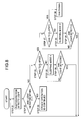
- Fig. 8 shows a second embodiment of the invention.
- the photodetector 18 is used as the means for detecting operation status of the construction machine 4.
- the descriptions for the time T1, the time T2, the time T3, and each of the sleeping modes are the same as those described in the first embodiment, and detailed description is not given here.
- the level is detected by receiving and detecting the laser beam 13 at the photodetection device 2. Therefore, if it is watched carefully whether light has been detected or not by the photodetection device 2, it is possible to detect whether the laser measuring system is in use or not.
- the power source of the laser rotary irradiation device is turned on, the power source of the photodetection device 2 is turned on, and operation of the laser measuring system is started.
- the photodetector 18 of the photodetection device 2 receives the laser beam 13. By the receiving of the laser beam 13, the photodetection device 2 confirms that the steady operation of the laser measuring system has been started (Step 21).
- the second arithmetic unit 43 checks at a predetermined time interval, e.g. at a time interval of one second whether there has been a photodetection signal or not from the photodetector 18. It is judged whether the photodetection signal has been received or not before the time T1 has elapsed (Step 22). When the photodetection signal is confirmed before the elapse of the time T1, it is judged that the operation of the construction machine 4 is currently continued, and the steady operations of the laser rotary irradiation device 1 and the photodetection device 2 are continued (Step 23).
- Step 22 When it is judged in Step 22 that there has been no photodetection signal within the time T1, it is judged further whether the time T2 has elapsed or not (Step 24).
- the sleeping mode 1 is selected.
- the power-saving program for the photodetection device is started, and the photodetection device 2 performs the power-saving control to match the sleeping mode 1.
- a sleeping mode 1 selecting instruction is transmitted from the second communication unit 20 to the first communication unit 16, and the laser rotary irradiation device 1 performs power-saving control according to the power-saving program for the laser rotary irradiation device 1 (Step 25).
- the laser measuring system is restored to the steady operation (Step 26).
- Step 27 In the case it is judged in Step 24 that the time T2 has elapsed, it is judged further whether the time T3 has elapsed or not (Step 27).
- the sleeping mode 2 is selected.
- the component members (circuits, sensor, etc.) other than the photodetector 18 and the second communication unit 20 are controlled and adjusted to the suspension status.
- a sleeping mode 2 selecting instruction is transmitted to the first communication unit 16 from the second communication unit 20.
- the laser rotary irradiation device 1 based on the received sleeping mode 2 selecting instruction and according to the power-saving program for the laser rotary irradiation device, the laser rotary irradiation device 1 is controlled and adjusted in the sleeping mode 2 (Step 28).
- Step 27 When it is judged in Step 27 that the time T3 has elapsed, the photodetection device 2 is shut down according to the power-saving program for the photodetection device, and the laser rotary irradiation device 1 is also shut down according to the power-saving program for laser rotary irradiation device (Step 30).
- Fig. 9 represents a third embodiment of the invention.
- the vibration sensor 49 is used as the means for detecting the operation status of the construction machine 4.
- the descriptions on the time T1, the time T2, the time T3 and each of the sleeping modes are the same as those described in the first embodiment, and detailed description is not given here.
- vibration of the mounting pole 7 is detected by the vibration sensor 49. Therefore, if it is carefully watched whether there is vibration or not by the vibration sensor 49, it is possible to detect that the laser measuring system is currently in use or not.
- the power source of the laser rotary irradiation device 1 is turned on, and the power source of the photodetection device 2 is also turned on. Then, the operation of the laser measuring system is started.
- the photodetection device 2 confirms that the laser measuring system has started the steady operation (Step 41).
- the second arithmetic unit 43 confirms, at a predetermined time interval, e.g. at a time interval of one second, whether a vibration detection signal has been issued from the vibration sensor 49 or not. It is judged whether the vibration detection signal has been issued or not before the elapse of the time T1 (Step 42). If the vibration detection signal is confirmed before the elapse of the time T1, it is judged that the operation by the construction machine 4 is being continued, and the steady operations of the laser rotary irradiation device 1 and the photodetection deice 2 are continued (Step 43).
- Step 44 In the case it is judged in Step 42 that the vibration detection signal has not been issued within the time T1, it is judged further whether the time T2 has elapsed or not (Step 44).
- the sleeping mode 1 is selected.
- the power-saving program for the photodetection device is started, and the photodetection device 2 performs the power-saving control to match the sleeping mode 1.
- a sleeping mode 1 selecting instruction is transmitted to the first communication unit 16 from the second communication unit 20, and the laser rotary irradiation device 1 performs power-saving control according to the power-saving program for the laser rotary irradiation device (Step 45).
- Step 47 it is judged further whether the time T3 has elapsed or not (Step 47).
- the sleeping mode 2 is selected (Step 48).
- the sleeping mode 2 operations of the component members (such as circuits and sensors like the photodetector 18, etc.) other than the vibration sensor 49 and the second communication unit 20 are controlled in the suspension status. Then, a sleeping mode 2 selecting instruction from the photodetection device 2 is transmitted to the first communication unit 16 from the second communication unit 20.
- the laser rotary irradiation device 1 is also controlled to the sleeping mode 2 based on the received sleeping mode 2 selecting instruction.
- Step 47 the photodetection device 2 is shut down according to the power-saving program for the photodetection device, and the laser rotary irradiation device 1 is shut down according to the power-saving program for the photodetection device, and the laser rotary irradiation device 1 is shut down according to the power-saving program for the laser rotary irradiation device (Step 50).
- the tilt sensor 48, the vibration sensor 49, and the photodetector 18 are individually used as the means for detecting the operation status of the construction machine 4, while it may be so designed that three of these detection means or any arbitrary two of these are combined together and are used as the means for detecting the operation status.
- the accuracy to detect the suspension status and the termination status of the laser measuring system can be improved, and this contributes to the prevention of erroneous operation in the transition to the sleeping mode.
- wasteful power consumption can be avoided without requiring the intervention of operation staff when the laser measuring system is not currently in use, and this is helpful in achieving successful power-saving effect.
Landscapes
- Engineering & Computer Science (AREA)
- Physics & Mathematics (AREA)
- Mechanical Engineering (AREA)
- Mining & Mineral Resources (AREA)
- Remote Sensing (AREA)
- Acoustics & Sound (AREA)
- Electromagnetism (AREA)
- Optics & Photonics (AREA)
- General Physics & Mathematics (AREA)
- Radar, Positioning & Navigation (AREA)
- Civil Engineering (AREA)
- General Engineering & Computer Science (AREA)
- Structural Engineering (AREA)
- Photometry And Measurement Of Optical Pulse Characteristics (AREA)
- Lasers (AREA)
- Operation Control Of Excavators (AREA)
Applications Claiming Priority (1)
| Application Number | Priority Date | Filing Date | Title |
|---|---|---|---|
| JP2007075362A JP4920467B2 (ja) | 2007-03-22 | 2007-03-22 | レーザ測定システムに於ける省電力制御方法及びレーザ測定システム |
Publications (3)
| Publication Number | Publication Date |
|---|---|
| EP1972891A2 true EP1972891A2 (de) | 2008-09-24 |
| EP1972891A3 EP1972891A3 (de) | 2009-09-02 |
| EP1972891B1 EP1972891B1 (de) | 2011-11-09 |
Family
ID=39535438
Family Applications (1)
| Application Number | Title | Priority Date | Filing Date |
|---|---|---|---|
| EP08250691A Active EP1972891B1 (de) | 2007-03-22 | 2008-02-29 | Stromsparsteuerungsverfahren in einem Lasermesssystem und Lasermesssystem |
Country Status (4)
| Country | Link |
|---|---|
| US (1) | US7483153B2 (de) |
| EP (1) | EP1972891B1 (de) |
| JP (1) | JP4920467B2 (de) |
| CN (1) | CN101270985B (de) |
Families Citing this family (8)
| Publication number | Priority date | Publication date | Assignee | Title |
|---|---|---|---|---|
| JP5199986B2 (ja) * | 2009-12-01 | 2013-05-15 | 日精樹脂工業株式会社 | 生産機械及びその運転方法 |
| JP5456532B2 (ja) * | 2010-03-25 | 2014-04-02 | 株式会社トプコン | 回転レーザ装置及び回転レーザシステム |
| KR101373998B1 (ko) * | 2012-09-19 | 2014-03-12 | 주식회사 현대미포조선 | 반목 레벨 측정 장치 |
| BR112017019454B1 (pt) * | 2015-03-13 | 2023-03-07 | 3M Innovative Properties Company | Dispositivo de detecção de luz |
| US10066939B2 (en) | 2015-10-13 | 2018-09-04 | Stanley Black & Decker Inc. | Laser level |
| CN105547491B (zh) * | 2015-12-17 | 2019-06-25 | 科盾科技股份有限公司 | 一种望远镜式激光测距热像仪的自动节电方法 |
| EP3526543B1 (de) | 2016-10-13 | 2024-02-28 | Stanley Black & Decker, Inc. | Elektrowerkzeug |
| CN111164379A (zh) * | 2018-09-07 | 2020-05-15 | 深圳市大疆创新科技有限公司 | 用于激光测距的方法和装置 |
Citations (2)
| Publication number | Priority date | Publication date | Assignee | Title |
|---|---|---|---|---|
| JP2000356517A (ja) | 1999-06-15 | 2000-12-26 | Topcon Corp | レーザー光検出装置 |
| EP1967818A2 (de) | 2007-03-06 | 2008-09-10 | Kabushiki Kaisha Topcon | Lasermesssystem |
Family Cites Families (4)
| Publication number | Priority date | Publication date | Assignee | Title |
|---|---|---|---|---|
| JP3670075B2 (ja) * | 1996-03-06 | 2005-07-13 | 株式会社トプコン | 適正高さ表示装置 |
| JPH11166832A (ja) | 1997-12-08 | 1999-06-22 | Nikon Corp | レーザ測量システム |
| JP4315860B2 (ja) | 2004-05-24 | 2009-08-19 | 株式会社トプコン | 建設機械制御システム |
| JP2006214850A (ja) | 2005-02-03 | 2006-08-17 | Sokkia Co Ltd | レーザ測量機 |
-
2007
- 2007-03-22 JP JP2007075362A patent/JP4920467B2/ja not_active Expired - Fee Related
-
2008
- 2008-02-27 US US12/072,635 patent/US7483153B2/en active Active
- 2008-02-29 EP EP08250691A patent/EP1972891B1/de active Active
- 2008-03-24 CN CN2008100872090A patent/CN101270985B/zh not_active Expired - Fee Related
Patent Citations (2)
| Publication number | Priority date | Publication date | Assignee | Title |
|---|---|---|---|---|
| JP2000356517A (ja) | 1999-06-15 | 2000-12-26 | Topcon Corp | レーザー光検出装置 |
| EP1967818A2 (de) | 2007-03-06 | 2008-09-10 | Kabushiki Kaisha Topcon | Lasermesssystem |
Also Published As
| Publication number | Publication date |
|---|---|
| JP2008232945A (ja) | 2008-10-02 |
| US20080231839A1 (en) | 2008-09-25 |
| EP1972891B1 (de) | 2011-11-09 |
| CN101270985A (zh) | 2008-09-24 |
| JP4920467B2 (ja) | 2012-04-18 |
| EP1972891A3 (de) | 2009-09-02 |
| CN101270985B (zh) | 2012-03-21 |
| US7483153B2 (en) | 2009-01-27 |
Similar Documents
| Publication | Publication Date | Title |
|---|---|---|
| US7483153B2 (en) | Power-saving control method in laser measuring system and laser measuring system | |
| EP1967818B1 (de) | Lasermesssystem | |
| US5742387A (en) | Laser beam levelling device and process for operating a laser beam levelling device and associated contrivance | |
| EP1607717B1 (de) | Positionsmesssystem | |
| US6449856B1 (en) | Laser plumbing device, long member plumbing device and long member plumbing method | |
| EP2551637B1 (de) | Rotierende laservorrichtung und rotierendes lasersystem | |
| US11703357B2 (en) | Method and system for calibrating laser level | |
| US20020185618A1 (en) | Distance Measuring system | |
| US6137567A (en) | Laser survey instrument | |
| JP4315860B2 (ja) | 建設機械制御システム | |
| US5757504A (en) | Positional measurement projecting device and mounting structure therefor | |
| JP2002267445A (ja) | ガイドレーザー光の方向設定作業システム | |
| JP2501081B2 (ja) | 基準平面設定装置 | |
| EP1380812A1 (de) | Laserbestrahlungsvorrichtung | |
| US6067148A (en) | Execution height display device and execution height setting system | |
| JP2916996B2 (ja) | レーザ測量装置 | |
| JP4477209B2 (ja) | 建設機械用の方向角測定装置 | |
| KR100450095B1 (ko) | 바닥면 수평 설정장치 및 그 방법 | |
| JP2022064814A (ja) | 作業支援システム、作業支援システムの制御方法 | |
| JP2006214850A (ja) | レーザ測量機 | |
| SE532694C2 (sv) | Anordning för positionering av ett hålverktyg medelst laserljus | |
| JP2006126102A (ja) | 測量用表示器とそれを用いた測量方法 | |
| SU1201407A1 (ru) | Система автоматического контрол погружени сваи | |
| JP4647797B2 (ja) | ガイドレーザ光の方向設定システム | |
| JPH0672011U (ja) | レーザ投光測量装置 |
Legal Events
| Date | Code | Title | Description |
|---|---|---|---|
| PUAI | Public reference made under article 153(3) epc to a published international application that has entered the european phase |
Free format text: ORIGINAL CODE: 0009012 |
|
| 17P | Request for examination filed |
Effective date: 20080311 |
|
| AK | Designated contracting states |
Kind code of ref document: A2 Designated state(s): AT BE BG CH CY CZ DE DK EE ES FI FR GB GR HR HU IE IS IT LI LT LU LV MC MT NL NO PL PT RO SE SI SK TR |
|
| AX | Request for extension of the european patent |
Extension state: AL BA MK RS |
|
| PUAL | Search report despatched |
Free format text: ORIGINAL CODE: 0009013 |
|
| AK | Designated contracting states |
Kind code of ref document: A3 Designated state(s): AT BE BG CH CY CZ DE DK EE ES FI FR GB GR HR HU IE IS IT LI LT LU LV MC MT NL NO PL PT RO SE SI SK TR |
|
| AX | Request for extension of the european patent |
Extension state: AL BA MK RS |
|
| AKX | Designation fees paid |
Designated state(s): CH DE FR GB IT LI |
|
| 17Q | First examination report despatched |
Effective date: 20100429 |
|
| GRAP | Despatch of communication of intention to grant a patent |
Free format text: ORIGINAL CODE: EPIDOSNIGR1 |
|
| GRAS | Grant fee paid |
Free format text: ORIGINAL CODE: EPIDOSNIGR3 |
|
| GRAA | (expected) grant |
Free format text: ORIGINAL CODE: 0009210 |
|
| AK | Designated contracting states |
Kind code of ref document: B1 Designated state(s): CH DE FR GB IT LI |
|
| REG | Reference to a national code |
Ref country code: GB Ref legal event code: FG4D |
|
| RIN1 | Information on inventor provided before grant (corrected) |
Inventor name: KATAYAMA, YASUTAKA Inventor name: YAMAZAKI, TAKAAKI |
|
| REG | Reference to a national code |
Ref country code: CH Ref legal event code: EP Ref country code: CH Ref legal event code: NV Representative=s name: KIRKER & CIE S.A. |
|
| REG | Reference to a national code |
Ref country code: DE Ref legal event code: R096 Ref document number: 602008011230 Country of ref document: DE Effective date: 20120216 |
|
| PLBE | No opposition filed within time limit |
Free format text: ORIGINAL CODE: 0009261 |
|
| STAA | Information on the status of an ep patent application or granted ep patent |
Free format text: STATUS: NO OPPOSITION FILED WITHIN TIME LIMIT |
|
| 26N | No opposition filed |
Effective date: 20120810 |
|
| REG | Reference to a national code |
Ref country code: DE Ref legal event code: R097 Ref document number: 602008011230 Country of ref document: DE Effective date: 20120810 |
|
| REG | Reference to a national code |
Ref country code: FR Ref legal event code: PLFP Year of fee payment: 9 |
|
| PGFP | Annual fee paid to national office [announced via postgrant information from national office to epo] |
Ref country code: IT Payment date: 20160222 Year of fee payment: 9 |
|
| PGFP | Annual fee paid to national office [announced via postgrant information from national office to epo] |
Ref country code: FR Payment date: 20160108 Year of fee payment: 9 Ref country code: GB Payment date: 20160224 Year of fee payment: 9 |
|
| GBPC | Gb: european patent ceased through non-payment of renewal fee |
Effective date: 20170228 |
|
| REG | Reference to a national code |
Ref country code: FR Ref legal event code: ST Effective date: 20171031 |
|
| PG25 | Lapsed in a contracting state [announced via postgrant information from national office to epo] |
Ref country code: FR Free format text: LAPSE BECAUSE OF NON-PAYMENT OF DUE FEES Effective date: 20170228 |
|
| PG25 | Lapsed in a contracting state [announced via postgrant information from national office to epo] |
Ref country code: IT Free format text: LAPSE BECAUSE OF NON-PAYMENT OF DUE FEES Effective date: 20170228 Ref country code: GB Free format text: LAPSE BECAUSE OF NON-PAYMENT OF DUE FEES Effective date: 20170228 |
|
| PGFP | Annual fee paid to national office [announced via postgrant information from national office to epo] |
Ref country code: CH Payment date: 20230307 Year of fee payment: 16 |
|
| PGFP | Annual fee paid to national office [announced via postgrant information from national office to epo] |
Ref country code: DE Payment date: 20221230 Year of fee payment: 16 |
|
| REG | Reference to a national code |
Ref country code: DE Ref legal event code: R119 Ref document number: 602008011230 Country of ref document: DE |
|
| REG | Reference to a national code |
Ref country code: CH Ref legal event code: PL |
|
| PG25 | Lapsed in a contracting state [announced via postgrant information from national office to epo] |
Ref country code: CH Free format text: LAPSE BECAUSE OF NON-PAYMENT OF DUE FEES Effective date: 20240229 |
|
| PG25 | Lapsed in a contracting state [announced via postgrant information from national office to epo] |
Ref country code: CH Free format text: LAPSE BECAUSE OF NON-PAYMENT OF DUE FEES Effective date: 20240229 |
|
| PG25 | Lapsed in a contracting state [announced via postgrant information from national office to epo] |
Ref country code: DE Free format text: LAPSE BECAUSE OF NON-PAYMENT OF DUE FEES Effective date: 20240903 |
|
| PG25 | Lapsed in a contracting state [announced via postgrant information from national office to epo] |
Ref country code: DE Free format text: LAPSE BECAUSE OF NON-PAYMENT OF DUE FEES Effective date: 20240903 |