EP1972293A2 - Injektionsvorrichtung - Google Patents
Injektionsvorrichtung Download PDFInfo
- Publication number
- EP1972293A2 EP1972293A2 EP08004484A EP08004484A EP1972293A2 EP 1972293 A2 EP1972293 A2 EP 1972293A2 EP 08004484 A EP08004484 A EP 08004484A EP 08004484 A EP08004484 A EP 08004484A EP 1972293 A2 EP1972293 A2 EP 1972293A2
- Authority
- EP
- European Patent Office
- Prior art keywords
- injection device
- sleeve
- hollow needle
- positioning
- parallel
- Prior art date
- Legal status (The legal status is an assumption and is not a legal conclusion. Google has not performed a legal analysis and makes no representation as to the accuracy of the status listed.)
- Withdrawn
Links
Images


Classifications
-
- A—HUMAN NECESSITIES
- A61—MEDICAL OR VETERINARY SCIENCE; HYGIENE
- A61M—DEVICES FOR INTRODUCING MEDIA INTO, OR ONTO, THE BODY; DEVICES FOR TRANSDUCING BODY MEDIA OR FOR TAKING MEDIA FROM THE BODY; DEVICES FOR PRODUCING OR ENDING SLEEP OR STUPOR
- A61M5/00—Devices for bringing media into the body in a subcutaneous, intra-vascular or intramuscular way; Accessories therefor, e.g. filling or cleaning devices, arm rests
- A61M5/178—Syringes
- A61M5/20—Automatic syringes, e.g. with automatically actuated piston rod, with automatic needle injection, filling automatically
-
- A—HUMAN NECESSITIES
- A61—MEDICAL OR VETERINARY SCIENCE; HYGIENE
- A61M—DEVICES FOR INTRODUCING MEDIA INTO, OR ONTO, THE BODY; DEVICES FOR TRANSDUCING BODY MEDIA OR FOR TAKING MEDIA FROM THE BODY; DEVICES FOR PRODUCING OR ENDING SLEEP OR STUPOR
- A61M5/00—Devices for bringing media into the body in a subcutaneous, intra-vascular or intramuscular way; Accessories therefor, e.g. filling or cleaning devices, arm rests
- A61M5/178—Syringes
- A61M5/31—Details
- A61M5/315—Pistons; Piston-rods; Guiding, blocking or restricting the movement of the rod or piston; Appliances on the rod for facilitating dosing ; Dosing mechanisms
- A61M5/31565—Administration mechanisms, i.e. constructional features, modes of administering a dose
- A61M5/31576—Constructional features; Drive mechanisms or modes for piston rods
- A61M5/31578—Constructional features; Drive mechanisms or modes for piston rods the piston rod being moved by the axial movement of a component directly in contact with it
-
- A—HUMAN NECESSITIES
- A61—MEDICAL OR VETERINARY SCIENCE; HYGIENE
- A61M—DEVICES FOR INTRODUCING MEDIA INTO, OR ONTO, THE BODY; DEVICES FOR TRANSDUCING BODY MEDIA OR FOR TAKING MEDIA FROM THE BODY; DEVICES FOR PRODUCING OR ENDING SLEEP OR STUPOR
- A61M5/00—Devices for bringing media into the body in a subcutaneous, intra-vascular or intramuscular way; Accessories therefor, e.g. filling or cleaning devices, arm rests
- A61M5/178—Syringes
- A61M5/31—Details
- A61M5/315—Pistons; Piston-rods; Guiding, blocking or restricting the movement of the rod or piston; Appliances on the rod for facilitating dosing ; Dosing mechanisms
- A61M5/31565—Administration mechanisms, i.e. constructional features, modes of administering a dose
- A61M5/31576—Constructional features; Drive mechanisms or modes for piston rods
- A61M5/31578—Constructional features; Drive mechanisms or modes for piston rods the piston rod being moved by the axial movement of a component directly in contact with it
- A61M5/31581—Constructional features; Drive mechanisms or modes for piston rods the piston rod being moved by the axial movement of a component directly in contact with it the component being manually operated or triggered by a rotating or pivoting actuator operated by user, e.g. an injection lever or handle
-
- A—HUMAN NECESSITIES
- A61—MEDICAL OR VETERINARY SCIENCE; HYGIENE
- A61B—DIAGNOSIS; SURGERY; IDENTIFICATION
- A61B34/00—Computer-aided surgery; Manipulators or robots specially adapted for use in surgery
- A61B34/20—Surgical navigation systems; Devices for tracking or guiding surgical instruments, e.g. for frameless stereotaxis
- A61B2034/2046—Tracking techniques
- A61B2034/2055—Optical tracking systems
-
- A—HUMAN NECESSITIES
- A61—MEDICAL OR VETERINARY SCIENCE; HYGIENE
- A61B—DIAGNOSIS; SURGERY; IDENTIFICATION
- A61B34/00—Computer-aided surgery; Manipulators or robots specially adapted for use in surgery
- A61B34/20—Surgical navigation systems; Devices for tracking or guiding surgical instruments, e.g. for frameless stereotaxis
-
- A—HUMAN NECESSITIES
- A61—MEDICAL OR VETERINARY SCIENCE; HYGIENE
- A61B—DIAGNOSIS; SURGERY; IDENTIFICATION
- A61B90/00—Instruments, implements or accessories specially adapted for surgery or diagnosis and not covered by any of the groups A61B1/00 - A61B50/00, e.g. for luxation treatment or for protecting wound edges
- A61B90/10—Instruments, implements or accessories specially adapted for surgery or diagnosis and not covered by any of the groups A61B1/00 - A61B50/00, e.g. for luxation treatment or for protecting wound edges for stereotaxic surgery, e.g. frame-based stereotaxis
- A61B90/11—Instruments, implements or accessories specially adapted for surgery or diagnosis and not covered by any of the groups A61B1/00 - A61B50/00, e.g. for luxation treatment or for protecting wound edges for stereotaxic surgery, e.g. frame-based stereotaxis with guides for needles or instruments, e.g. arcuate slides or ball joints
-
- A—HUMAN NECESSITIES
- A61—MEDICAL OR VETERINARY SCIENCE; HYGIENE
- A61M—DEVICES FOR INTRODUCING MEDIA INTO, OR ONTO, THE BODY; DEVICES FOR TRANSDUCING BODY MEDIA OR FOR TAKING MEDIA FROM THE BODY; DEVICES FOR PRODUCING OR ENDING SLEEP OR STUPOR
- A61M5/00—Devices for bringing media into the body in a subcutaneous, intra-vascular or intramuscular way; Accessories therefor, e.g. filling or cleaning devices, arm rests
- A61M5/178—Syringes
- A61M5/31—Details
- A61M5/32—Needles; Details of needles pertaining to their connection with syringe or hub; Accessories for bringing the needle into, or holding the needle on, the body; Devices for protection of needles
- A61M5/3287—Accessories for bringing the needle into the body; Automatic needle insertion
-
- A—HUMAN NECESSITIES
- A61—MEDICAL OR VETERINARY SCIENCE; HYGIENE
- A61M—DEVICES FOR INTRODUCING MEDIA INTO, OR ONTO, THE BODY; DEVICES FOR TRANSDUCING BODY MEDIA OR FOR TAKING MEDIA FROM THE BODY; DEVICES FOR PRODUCING OR ENDING SLEEP OR STUPOR
- A61M5/00—Devices for bringing media into the body in a subcutaneous, intra-vascular or intramuscular way; Accessories therefor, e.g. filling or cleaning devices, arm rests
- A61M5/42—Devices for bringing media into the body in a subcutaneous, intra-vascular or intramuscular way; Accessories therefor, e.g. filling or cleaning devices, arm rests having means for desensitising skin, for protruding skin to facilitate piercing, or for locating point where body is to be pierced
- A61M5/427—Locating point where body is to be pierced, e.g. vein location means using ultrasonic waves, injection site templates
Definitions
- the present invention relates to an injection device and its use for the injection of pharmaceutical compositions, in the medical therapeutic treatment with computer-aided positioning, such as for computer-aided surgery.
- the injection device according to the invention is particularly suitable for injection in the periradicular therapy, because it is suitable for a precise determination of the positioning of its hollow needle.
- the injection device according to the invention comprises a device for precise positioning of a hollow needle, without a direct optical control of the positioning of the outlet end of the hollow needle would be required.
- the EP 1 543 789 B1 describes an instrument for use in computer-aided surgery, whose instrument shaft has a reference star adapter, which is arranged directly on the instrument shaft and rotatably mounted on an adapter interface. In this way, a predeterminable axial position of the reference star adapter is to be provided.
- the EP 1 733 693 A1 describes the coordination of devices and surgical instruments via wireless data transmission to a central control and reception unit.
- reference stars can be used, which can also be fixed to the patient to be treated.
- periradicular therapy in which pharmaceutical compositions, for example analgesics, are injected between vertebrae, it is known to determine the positioning of the hollow needle used for the injection by two-dimensional fluoroscopy or computed tomography, optionally coupled with an image converter.
- computed tomography the patient to be treated is first scanned by computer tomography, wherein in the generated image the puncture site and puncture angle can be calculated and identified on the back of the patient.
- the hollow needle is then under computertomografischer Control is advanced, whereupon to control the positioning of the hollow needle contrast agent is injected. After achieving the desired positioning of the hollow needle then a pharmaceutical agent can be injected.
- a disadvantage of the known methods for the position-specific injection of pharmaceutical compositions is that a complex control of the positioning of the hollow needle by X-ray or computed tomography must be carried out, if necessary, in addition, the injection of a contrast agent. This makes the treatment technically and time consuming.
- the present invention therefore has for its object to provide a device and a method for periradicular therapy, which avoids the disadvantages of the prior art.
- the invention is based on the observation that a determination of the positioning of the hollow needle according to the prior art is not possible if only the position and orientation of the still visible end of the hollow needle can be determined. Because conventional hollow needles are elastic and change the linear shape depending on the structure and strength of the surrounding tissue.
- the invention solves the above objects by providing an injection device in which the hollow needle is stabilized by a conically tapered sleeve, or a conically tapered sleeve is provided, wherein the sleeve is fixed with one end and the injection device one with the sleeve connected reference star has.
- a reference star connected to the sleeve is connected to the injection device in such a way that the position of the sleeve relative to this reference star is known or determinable and unchangeable in the mounted state.
- the reference star can be mounted on a housing in which the associated with the sleeve or hollow needle reservoir for receiving pharmaceutical compositions is arranged.
- the combination of the provided by the sleeve bending strength of the injection needle for determining the positioning of the injection device with the reference star, which is connected to the sleeve, allows the determination of the positioning of the sleeve and thus the hollow needle over its entire length.
- the method that can be carried out with the injection device according to the invention is based on the determinability of the positioning of the sleeve and the hollow needle provided in or through it during the injection of a pharmaceutical composition, preferably for periradicular therapy.
- the injection device which also has a dosing chamber connected to the single-sidedly fixed hollow needle, or the one-sidedly fixed, conically tapered sleeve, can be detected with respect to its positioning by means of its reference star.
- the relative positioning of the injection device and its sleeve is accomplished by correlation with the position of the patient to be treated.
- the position of the patient to be treated can be determined by reference stars, which are fixedly connected to the patient.
- the relative positioning of a reference star associated with the patient may be determined or confirmed by known methods, such as x-ray or computed tomography, and is preferably continuously detectable.
- the method that can be carried out with the device according to the invention therefore comprises the determination of the position of the sleeve by measuring the position of the reference star, preferably in conjunction with the measurement of the position of a reference star connected to the patient, then advancing the sleeve in its longitudinal axis into the patient, determining their position Position by measuring the position of the reference star of the injection device.
- the relative positioning of the sleeve and the associated hollow needle for injection relative to the reference star of the injection device is due to the dimensions of the injection device and the position of the sleeve with respect to the reference star determinable or known. Accordingly, the positioning of the sleeve and thus the hollow needle from the positioning of the reference star of the injection device can be derived.
- the conical, tapered sleeve is formed integrally with the arranged in its axial recess Hohnadel.
- reference stars can be calibrated using a special calibration block (ICM, Instrument Calibration Matrix).
- ICM Instrument Calibration Matrix
- the position determination can be carried out by any known detection system for reference stars.
- the Position determination of the reference stars continuously, for example by determining the position by measuring the radiation reflected by the position of the stars, in particular infrared radiation.
- the invention also relates to the combination of the injection device according to the invention with a system for determining the position of reference stars with a device for emitting radiation and for detecting reflected radiation, preferably of IR radiation.
- the device for determining the position of the reference stars on the injection device and on the patient on an output unit for imaging the positions of the reference stars, in which also from the positioning of the reference stars calculated to each other position of the sleeve can be displayed.
- the sleeve may have the conical, tapered shape in that its outer diameter tapers stepwise in steps from the end to which it is fixed in the device according to the invention.
- the dosing chamber connected to the hollow needle, which contains the pharmaceutical composition to be injected can be operated by means of a pistol grip.
- a pistol grip which is arranged on the injection device for operating the metering chamber, allows the dosage of the pharmaceutical composition to be injected while simplifying the handling of the device, in particular for the safe manual guidance of the injection device on the pistol grip.
- the injection device according to the invention has a guide rail on which it can be displaceably guided in the direction of the axis of the sleeve, while the positioning of the rail can be adjusted and fixed in any direction in space.
- the rail can be fixed for example by means of an adjustable arm in a desired position relative to an operating table, for example attached to the operating table. In this way, the movement of the sleeve of the injection device in the direction of its axis is limited to the displacement along the rail and can therefore be predetermined with prior fixation of the splint relative to an operating table, or relative to a patient.
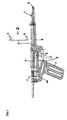
- Fig. 1 shows a schematic view of a first embodiment of the injection device according to the invention
- Fig. 2 a schematic view of a second embodiment with conical, tapered sleeve shows
- FIG. 3 a schematic view of another embodiment of the injection device according to the invention with a guide shows
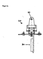
- Fig. 4a a schematic view of a preferred embodiment of the parallel guide for the injection device according to the invention
- Fig. 4b a 90 ° rotated view of Fig. 4a
- Fig. 4c a top-down view Fig. 4b .
- Fig. 1 shows the sleeve 1 and with an axially disposed therein hollow needle 2 at one end of the injection device.
- this has a reference star 3, which can be fixed.
- the reference star 3 has at least three sections, by means of which its positioning in space, eg in relation to a detection unit or in relation to another reference star, can be determined.
- these sections are balls.
- two balls 4 of a reference star are shown schematically.
- the sleeve 1 is formed so as to taper stepwise from the end which is fixed to the end which is exposed and can be inserted for piercing. Also shown is the embodiment in which the sleeve 1 surrounds a hollow needle 2. Alternatively, it is also possible that sleeve 1 and hollow needle 2 are integrally formed.
- the injection device has a reservoir 5 connected to the hollow needle 2 for receiving a pharmaceutical composition which can be emptied through the hollow needle 2 by means of a displaceable piston 6.
- a displaceable piston 6 As an alternative to a piston as an actuating device for the emptying of the reservoir 5, another device for generating an overpressure in the reservoir 5 is used, for example a pump.
- the injection device preferably has a pistol grip 7, in which a pivot lever 8 is pivotally mounted, wherein the pivoting of the pivot lever 8 leads to the advancement of the piston 6 in the reservoir 5.
- a pivot lever 8 is pivotally mounted, wherein the pivoting of the pivot lever 8 leads to the advancement of the piston 6 in the reservoir 5.
- force is exemplified one end of a pull 9 connected to its one end of the pivot lever 8, and with its other end with a parallel and displaceable in the direction of the hollow needle 2 pressure piece 10.
- the pressure piece 10 is preferably provided with a locking device 11, which allows a displacement of the pressure member 10 only in the direction of the hollow needle 2, but prevents slipping back of the hollow needle 2 away.
- Fig. 2 shows a second embodiment of the present invention, in which the sleeve 1 is not tapered stepwise, but continuously tapered and, for example, tapered.
- the hollow needle it is also possible for the hollow needle to have a constant diameter, eg in the form of a tube, and a subsequent second section in a first section which adjoins the end with which the sleeve 1 is fixed in the device. which extends to the free tip of the sleeve 1, wherein only this second section tapers conically.
- the sleeve 1 may be integral with the hollow needle 2 disposed therein.
- Fig. 3 shows schematically the arrangement of an injection device according to the invention on a parallel guide, wherein the injection device is arranged on the parallel guide 20 so that it is only displaceable along the axis of the sleeve 1.
- the parallel guide 20 may, for example, have a groove 21 in which the injection device is displaceable against rotation and tilt.
- the parallel guide is arranged on an arm 22 which is movable in any position with respect to a base 23 and in this position can be fixed.
- the injection device according to the invention allows the determination of the position of the injection device, and thus the arrangement of its sleeve 1 with the guided or integrally formed hollow needle 2 using the reference star 3.
- the pistol grip 7 allows easy handling of the injection device, which is essential for practical application, since not inconsiderable forces have to be overcome for the injection.
- the particular embodiment of the sleeve 1 prevents its bending during the insertion of the sleeve 1 in the body of the patient, so that even during use of the position of the reference star 3, the position of the sleeve 1 with the hollow needle 2 can be determined.
- the injection device according to the invention allows the precise and predictable introduction of the sleeve 1 with the arranged therein Hollow needle 2. In this way an uncontrolled penetration of a hollow needle is avoided, as it is known, for example, with insufficient resistance to the bending of the prior art.
- the injection device according to the invention On a parallel guide 20, so that the sleeve 1 is displaceable exclusively in the direction of its axis.
- the orientation of the parallel guide 20 therefore leads to the alignment of the reference star 3 of the injection device, so that a predetermined, desired position and orientation relative to the desired puncture site is possible.
- the fixation of the parallel guide 20 in the desired position and orientation by locking the arm 22.
- the advance of the injection device along the parallel guide 20 can be done by manual operation, or by motor propulsion, for example, computer controlled with an electric drive
- the arrangement of the hollow needle 2 within the sleeve 1 prevents substantial bending of the hollow needle 2, so that a deviation of the actual positioning and orientation of the hollow needle 2 within the patient from the positioning and orientation is substantially avoided, resulting from the arrangement of the sleeve 1 within the injection device results.
- Fig. 4a-c show in detail a parallel guide 20, with an orientation and positioning of the sleeve after fixing the parallel guide only in the direction of the hollow needle is possible.
- the parallel guide has a groove 21 in a rail 24, in which a carrier 25 by means of guide elements 26, such as guide pins, is displaceably guided.
- the injection device preferably with pistol grip, can be mounted on the carrier 25.
- the sleeve (not shown) is displaceable only parallel to the groove 21.
- the sleeve is displaceable only parallel to the groove 21.
- the sleeve is arranged parallel to the groove 21, so that it is arranged displaceable on the parallel guide only in the direction of its axis.
- the parallel guide 20 may have a bore or laterally accessible guide recess 27.
- the carrier 25 may be made in two parts and have a first support plate 28 which is displaceably mounted in the groove 21 by means of guide elements 26, and a second support plate 29 which is parallel to the first support plate 28 pivotable.
- the second support plate 29 then serves to receive the injection device and can be pivoted with this against the first support plate 28. In this way, the injection device, or its sleeve, can be adjusted in position to the groove 21 of the parallel guide 20.
- the parallel guide 20 preferably has a pivoting device 30, whose pivot axis is arranged at an angle, preferably perpendicular, to the guide groove 21.
- This pivoting device 30 may have two elements arranged in parallel, the about a lockable pivot axis (not shown) are pivotable, and / or by pins 31 of the one element, which are guided in one or more concentric arcuate slots 32 of the other element. Boreholes 33 are used for fixing to an arm 22.
- the guide of the carrier 25 can also be realized by other functional elements which enable a parallel displacement of the carrier 25 along a rail 24.
- the parallel guide 20 may be provided with one or more reference stars, for example on the slide 24, to determine the relative orientation of the injection device and splint.
- the parallel guide described herein for use with the injection device may also be used to support other surgical instruments to realize their parallel displaceability along the groove 21.
- Such other surgical instruments may be, for example, drills and screwdrivers.
Landscapes
- Health & Medical Sciences (AREA)
- Vascular Medicine (AREA)
- Engineering & Computer Science (AREA)
- Anesthesiology (AREA)
- Biomedical Technology (AREA)
- Heart & Thoracic Surgery (AREA)
- Hematology (AREA)
- Life Sciences & Earth Sciences (AREA)
- Animal Behavior & Ethology (AREA)
- General Health & Medical Sciences (AREA)
- Public Health (AREA)
- Veterinary Medicine (AREA)
- Infusion, Injection, And Reservoir Apparatuses (AREA)
Abstract
Die Erfindung bezieht sich auf eine Injektionsvorrichtung für die computergestützte Chirurgie mit einer an einem Ende fixierten Hohlnadel (2) und einem mit dieser verbundenen Reservoir (5). Die Injektionsvorrichtung zeichnet sich aus durch einen Referenzstern (3) und eine konische, spitz zulaufende Hülse (1) mit axialer Ausnehmung, in der die Hohlnadel (2) angeordnet ist, wobei die Hülse (1) mit dem Ende in der Injektionsvorrichtung fixiert ist, an dem die Hohlnadel (1) fixiert ist. Die Erfindung bezieht sich auch auf eine mit einer solchen Injektionsvorrichtung verwendbare Parallelführung (20).
Description
- Die vorliegende Erfindung betrifft eine Injektionsvorrichtung und deren Verwendung für die Injektion pharmazeutischer Zusammensetzungen, in der medizinischtherapeutischen Behandlung mit computergestützter Positionierung, wie beispielsweise für die computergestützte Chirurgie.
- Die erfindungsgemäße Injektionsvorrichtung ist insbesondere zur Injektion in der periradikulären Therapie geeignet, weil sie für eine präzise Bestimmung der Positionierung ihrer Hohlnadel geeignet ist. Auf diese Weise enthält die erfindungsgemäße Injektionsvorrichtung eine Vorrichtung zur präzisen Positionierung einer Hohlnadel, ohne dass eine direkte optische Kontrolle der Positionierung des Austrittsendes der Hohlnadel erforderlich wäre.
- Die
EP 1 543 789 B1 beschreibt ein Instrument für den Einsatz in der computergestützten Chirurgie, dessen Instrumentenschaft einen Referenzstern - Adapter aufweist, der direkt am Instrumentenschaft und um diesen drehbar an einer Adaptionsschnittstelle angeordnet ist. Auf diese Weise soll eine vorherbestimmbare Axialposition des Referenzstern - Adapters bereitgestellt werden. - Die
EP 1 733 693 A1 beschreibt die Koordinierung von Geräten und chirurgischen Instrumenten mittels drahtloser Datenübertragung zu einer zentralen Steuerungs- und Empfangseinheit. Zur Ortung der Position von Instrumenten können Referenzsterne eingesetzt werden, die ebenfalls an dem zu behandelnden Patienten fixiert werden können. - Zur periradikulären Therapie, bei der pharmazeutische Zusammensetzungen, beispielsweise Schmerzmittel, zwischen Wirbel injiziert werden, ist es bekannt, die Positionierung der zur Injektion eingesetzten Hohlnadel durch zweidimensionale Röntgendurchleuchtung oder Computertomografie, optional gekoppelt mit einem Bildwandler, zu bestimmen. Für die Bestimmung der Positionierung der Hohlnadel mittels Computertomografie wird der zu behandelnde Patient zunächst computertomografisch abgetastet, wobei in dem erzeugten Bild Punktionsstelle und Einstichwinkel berechnet und auf dem Rücken des Patienten identifiziert werden können. Die Hohlnadel wird anschließend unter computertomografischer Kontrolle vorgeschoben, woraufhin zur Kontrolle der Positionierung der Hohlnadel Kontrastmittel injiziert wird. Nach Erreichen der erwünschten Positionierung der Hohlnadel kann dann ein pharmazeutischer Wirkstoff injiziert werden.
- An den bekannten Verfahren zur positionsbestimmten Injektion von pharmazeutischen Zusammensetzungen ist nachteilig, dass eine aufwändige Kontrolle der Positionierung der Hohlnadel durch Röntgen oder Computertomografie erfolgen muss, gegebenenfalls sogar zusätzlich die Injektion eines Kontrastmittels. Dadurch wird die Behandlung technisch und zeitlich aufwändig.
- Der vorliegenden Erfindung stellt sich daher die Aufgabe, eine Vorrichtung und ein Verfahren zur periradikulären Therapie bereitzustellen, die die Nachteile des Standes der Technik vermeidet.
- Die Erfindung beruht auf der Beobachtung, dass eine Bestimmung der Positionierung der Hohlnadel nach dem Stand der Technik nicht möglich ist, wenn nur die Lage und Ausrichtung des noch sichtbaren Endes der Hohlnadel bestimmbar ist. Denn herkömmliche Hohlnadeln sind elastisch und verändern die lineare Form in Abhängigkeit von der Struktur und Festigkeit des umgebenden Gewebes.
- Die Erfindung löst die vorgenannten Aufgaben durch Bereitstellung einer Injektionsvorrichtung, bei der die Hohlnadel durch eine konisch spitz zulaufende Hülse stabilisiert wird, bzw. eine konisch, spitz zulaufenden Hülse bereitgestellt ist, wobei die Hülse mit einem Ende festgelegt ist und die Injektionsvorrichtung einen mit der Hülse verbundenen Referenzstern aufweist. Dabei ist ein mit der Hülse verbundener Referenzstern so mit der Injektionsvorrichtung verbunden, dass die Position der Hülse zu diesem Referenzstern bekannt oder bestimmbar ist und im montierten Zustand unveränderlich ist. So kann der Referenzstern an einem Gehäuse montiert sein, in dem das mit der Hülse bzw. Hohlnadel verbundene Reservoir zur Aufnahme pharmazeutischer Zusammensetzungen angeordnet ist.
- Die Kombination der durch die Hülse bereitgestellten Biegefestigkeit der zur Injektion eingesetzten Hohlnadel mit der Bestimmung der Positionierung der Injektionsvorrichtung anhand des Referenzsterns, der mit der Hülse verbunden ist, ermöglicht die Bestimmung der Positionierung der Hülse und damit der Hohlnadel über deren gesamte Baulänge.
- Das mit der erfindungsgemäßen Injektionsvorrichtung durchführbare Verfahren beruht auf der Bestimmbarkeit der Positionierung der Hülse und der in dieser oder durch diese bereitgestellten Hohlnadel während der Injektion einer pharmazeutischen Zusammensetzung, vorzugsweise zur periradikulären Therapie. Die Injektionsvorrichtung, die auch eine mit der einseitig fixierten Hohlnadel, bzw. der einseitig fixierten, konisch spitz zulaufenden Hülse verbundene Dosierkammer aufweist, kann mittels ihres Referenzsterns bezüglich ihrer Positionierung detektiert werden. Die relative Positionierung der Injektionsvorrichtung und ihrer Hülse erfolgt durch Korrelation mit der Position des zu behandelnden Patienten. Die Position des zu behandelnden Patienten kann durch Referenzsterne bestimmt werden, die ortsfest mit dem Patienten verbunden sind. Die relative Positionierung eines mit dem Patienten verbundenen Referenzsterns kann durch bekannte Verfahren, beispielsweise durch Röntgen oder Computertomografie, bestimmt oder bestätigt werden, und ist vorzugsweise kontinuierlich erfassbar. Das mit der erfindungsgemäßen Vorrichtung durchführbare Verfahren umfasst daher die Bestimmung der Position der Hülse durch Messung der Position des Referenzsterns, vorzugsweise in Verbindung mit der Messung der Position eines mit dem Patienten verbundenen Referenzsterns, anschließendes Vorschieben der Hülse in ihrer Längsachse in den Patienten unter Bestimmung ihrer Position durch Messung der Position des Referenzsterns der Injektionsvorrichtung.
- Die relative Positionierung der Hülse und der mit ihr verbundenen Hohlnadel zur Injektion relativ zu dem Referenzstern der Injektionsvorrichtung ist auf Grund der Abmessungen der Injektionsvorrichtung und der Lage der Hülse in Bezug auf den Referenzstern bestimmbar, bzw. bekannt. Entsprechend ist die Positionierung der Hülse und damit der Hohlnadel aus der Positionierung des Referenzsterns der Injektionsvorrichtung ableitbar.
- In bevorzugter Ausführungsform ist die konisch, spitz zulaufende Hülse mit der in ihrer axialen Ausnehmung angeordneten Hohnadel einstückig ausgebildet.
- Zur Bestimmung der Positionen von Referenzsternen in Bezug auf ein angelegtes Koordinatensystem, bzw. relativ zueinander, können Referenzsterne unter Zuhilfenahme eines speziellen Kalibrierblocks (ICM, Instrument Calibration Matrix) kalibriert werden. Als Alternative zu dieser sogenannten Vorkalibrierung kann die Positionsbestimmung durch jedes bekannte Erfassungssystem für Referenzsterne erfolgen. Vorzugsweise erfolgt die Positionsbestimmung der Referenzsterne kontinuierlich, beispielsweise durch Positionsbestimmung mittels Messung der von den Positionssternen reflektierten Strahlung, insbesondere Infrarotstrahlung. Entsprechend betrifft die Erfindung auch die Kombination der erfindungsgemäßen Injektionsvorrichtung mit einem System zur Positionsbestimmung von Referenzsternen mit einer Einrichtung zur Abstrahlung von Strahlung und zur Detektion reflektierter Strahlung, vorzugsweise von IR-Strahlung. Weiter bevorzugt weist die Vorrichtung zur Positionsbestimmung der Referenzsterne an der Injektionsvorrichtung und am Patienten eine Ausgabeeinheit zur bildlichen Darstellung der Positionen der Referenzsterne auf, in der auch die aus der Positionierung der Referenzsterne zueinander errechnete Position der Hülse darstellbar ist.
- In einer weniger bevorzugten Ausführungsform kann die Hülse die konische, spitz zulaufende Form dadurch aufweisen, dass sich ihr Außendurchmesser abschnittsweise stufenförmig von dem Ende, an dem sie in der erfindungsgemäßen Vorrichtung fixiert ist, verjüngt.
- In weiter bevorzugter Ausführungsform ist die mit der Hohlnadel verbundene Dosierkammer, die die zu injizierende pharmazeutische Zusammensetzung enthält, mittels eines Pistolengriffs bedienbar. Ein Pistolengriff, der an der Injektionsvorrichtung zur Bedienung der Dosierkammer angeordnet ist, ermöglicht die Dosierung der zu injizierenden pharmazeutischen Zusammensetzung bei gleichzeitiger Vereinfachung der Handhabung der Vorrichtung, insbesondere zur sicheren manuellen Führung der Injektionsvorrichtung an dem Pistolengriff.
- In weiter bevorzugter Ausführungsform weist die erfindungsgemäße Injektionsvorrichtung eine Führungsschiene auf, an der sie in Richtung der Achse der Hülse verschieblich geführt werden kann, während die Positionierung der Schiene in jeder Richtung im Raum eingestellt und fixiert werden kann. Die Schiene ist beispielsweise mittels eines einstellbaren Arms in einer gewünschten Position relativ zu einem Operationstisch fixierbar, beispielsweise am Operationstisch befestigt. Auf diese Weise wird die Bewegung der Hülse der Injektionsvorrichtung in Richtung ihrer Achse auf die Verschiebung entlang der Schiene beschränkt und kann daher bei vorheriger Fixierung der Schiene relativ zu einem Operationstisch, bzw. relativ zu einem Patienten, vorherbestimmt werden.
- Die Erfindung wird nun genauer mit Bezug auf die Figuren beschrieben, in denen
-
Fig. 1 eine schematische Ansicht einer ersten Ausführungsform der erfindungsgemäßen Injektionsvorrichtung zeigt, -
Fig. 2 eine schematische Ansicht einer zweiten Ausführungsform mit konischer, spitz zulaufender Hülse zeigt -
Fig. 3 eine schematische Ansicht einer weiteren Ausführungsform der erfindungsgemäßen Injektionsvorrichtung mit einer Führung zeigt -
Fig. 4a eine schematische Ansicht einer bevorzugten Ausführung der Parallelführung für die erfindungsgemäße Injektionsvorrichtung, -
Fig. 4b eine um 90° gedrehte Ansicht vonFig. 4a und -
Fig. 4c eine Aufsicht von rechts aufFig. 4b . - In den Figuren bezeichnen gleiche Bezugsziffern funktionsgleiche Teile.
- Die Ausführungsform von
Fig. 1 zeigt die Hülse 1 und mit einer darin axial angeordneten Hohlnadel 2 an einem Ende der Injektionsvorrichtung. Zur Erfassung der Position der Injektionsvorrichtung weist diese einen Referenzstern 3 auf, der fixierbar ist. Der Referenzstern 3 weist zumindest drei Abschnitte auf, anhand derer seine Positionierung im Raum, z.B. im Verhältnis zu einer Detektionseinheit oder im Verhältnis zu einem anderen Referenzstern, bestimmbar ist. Vorzugsweise sind diese Abschnitte Kugeln. In den Figuren sind zwei Kugeln 4 eines Referenzsterns schematisch dargestellt. - In dieser Ausführungsform ist die Hülse 1 so ausgebildet, dass sie sich abschnittsweise von dem Ende, das festgelegt ist, zu dem Ende, das frei liegt und zum Einstechen eingesetzt werden kann, stufenförmig verjüngt. Weiter dargestellt ist die Ausführungsform, in der die Hülse 1 eine Hohlnadel 2 umgibt. Alternativ ist es auch möglich, dass Hülse 1 und Hohlnadel 2 einstückig geformt sind.
- Die Injektionsvorrichtung weist ein mit der Hohlnadel 2 verbundenes Reservoir 5 zur Aufnahme einer pharmazeutischen Zusammensetzung auf, das mittels eines verschieblichen Kolbens 6 durch die Hohlnadel 2 entleert werden kann. Als Alternative zu einem Kolben als Betätigungsvorrichtung für das Entleeren des Reservoirs 5 ist auch eine andere Einrichtung zur Erzeugung eines Überdrucks in dem Reservoir 5 einsetzbar, beispielsweise eine Pumpe.
- Zur Betätigung des Kolbens 6 weist die Injektionsvorrichtung vorzugsweise einen Pistolengriff 7 auf, in dem ein Schwenkhebel 8 verschwenkbar angeordnet ist, wobei die Verschwenkung des Schwenkhebels 8 zum Vorschub des Kolbens 6 in das Reservoir 5 führt. Zur Übertragung der vom Schwenkhebel 8 auf den Kolben 6 ausgeübten Kraft ist beispielhaft ein Ende eines Zugstücks 9 mit seinem einen Ende des Schwenkhebels 8 verbunden, und mit seinem anderen Ende mit einem parallel und in Richtung der Hohlnadel 2 verschieblichen Druckstück 10. Das Druckstück 10 ist vorzugsweise mit einer Rasteinrichtung 11 versehen, die ein Verschieben des Druckstücks 10 nur in Richtung auf die Hohlnadel 2 erlaubt, jedoch ein Zurückrutschen von der Hohlnadel 2 weg verhindert.
-
Fig. 2 zeigt eine zweite Ausführungsform der vorliegenden Erfindung, bei der sich die Hülse 1 nicht stufenförmig verjüngt, sondern kontinuierlich und z.B. kegelförmig spitz zuläuft. Bei dieser Ausführungsform ist es auch möglich, dass die Hohlnadel in einem ersten Abschnitt, der an das Ende angrenzt, mit dem die Hülse 1 in der Vorrichtung fixiert ist, einen konstanten Durchmesser aufweist, z.B. in Form eines Rohrs, und einen anschließenden zweiten Abschnitt, der sich bis zur freien Spitze der Hülse 1 erstreckt, wobei nur dieser zweiter Abschnitt kegelförmig spitz zuläuft. - Auch bei dieser zweiten Ausführungsform kann die Hülse 1 einstückig mit der darin angeordneten Hohlnadel 2 sein.
-
Fig. 3 zeigt schematisch die Anordnung einer erfindungsgemäßen Injektionsvorrichtung auf einer Parallelführung, wobei die Injektionsvorrichtung so auf der Parallelführung 20 angeordnet ist, dass sie nur noch entlang der Achse der Hülse 1 verschieblich ist. Die Parallelführung 20 kann z.B. eine Nut 21 aufweisen, in der dreh- und kippsicher die Injektionsvorrichtung verschieblich ist. Die Parallelführung ist an einem Arm 22 angeordnet, der in jede beliebige Position in Bezug auf eine Unterlage 23 beweglich ist und in dieser Position fixierbar ist. - Die erfindungsgemäße Injektionsvorrichtung ermöglicht anhand des Referenzsterns 3 die Bestimmung der Position der Injektionsvorrichtung, und damit der Anordnung ihrer Hülse 1 mit der darin geführten oder einstückig geformten Hohlnadel 2. Der Pistolengriff 7 ermöglicht eine einfache Handhabung der Injektionsvorrichtung, was für die praktische Anwendung wesentlich ist, da für die Injektion nicht unerhebliche Kräfte überwunden werden müssen.
- Die besondere Ausführungsform der Hülse 1 verhindert deren Verbiegung während des Einführens der Hülse 1 in den Körper des Patienten, sodass auch während der Verwendung anhand der Position des Referenzsterns 3 die Position der Hülse 1 mit der Hohlnadel 2 feststellbar ist. In Kombination mit der Bestimmung der Positionierung der gewünschten Einstichstelle und Einstichrichtung, beispielsweise anhand der Positionierung eines zweiten Referenzsterns, der in bekannter Position relativ zur gewünschten Einstichstelle angeordnet und orientiert ist, ermöglicht die erfindungsgemäße Injektionsvorrichtung die präzise und vorherbestimmbare Einführung der Hülse 1 mit der darin angeordneten Hohlnadel 2. Auf diese Weise wird ein unkontrolliertes Eindringen einer Hohlnadel vermieden, wie sie beispielsweise mit unzureichender Festigkeit gegen die Verbiegung aus dem Stand der Technik bekannt ist.
- Zur Vermeidung von Positionierungsfehlern der Hülse 1 ist bevorzugt, die erfindungsgemäße Injektionsvorrichtung auf einer Parallelführung 20 anzuordnen, sodass die Hülse 1 ausschließlich in Richtung ihrer Achse verschieblich ist. Die Ausrichtung der Parallelführung 20 führt daher zur Ausrichtung des Referenzsterns 3 der Injektionsvorrichtung, sodass eine vorbestimmte, gewünschte Position und Orientierung relativ zur gewünschten Einstichstelle möglich ist. Die Fixierung der Parallelführung 20 in der gewünschten Position und Orientierung erfolgt durch Arretierung des Arms 22. Der Vorschub der Injektionsvorrichtung entlang der Parallelführung 20kann durch manuelle Betätigung erfolgen, oder durch motorischen Vortrieb, beispielsweise computergesteuert mit einem elektrischen Antrieb Zur Behandlung eines Patienten mit der erfindungsgemäßen Vorrichtung ist es bevorzugt, die Injektionsvorrichtung relativ zu einem zweiten Referenzstern, der mit dem Patienten verbunden ist, so auszurichten, dass der Referenzstern 3 der Injektionsvorrichtung so positioniert und ausgerichtet wird, dass die Hülse 1 die gewünschte Position und Orientierung einnimmt. Ausüben von Druck auf das Reservoir 5 wird die darin befindliche pharmazeutische Zusammensetzung durch die Hohlnadel 2 austreten gelassen. Die Anordnung der Hohlnadel 2 innerhalb der Hülse 1 verhindert eine wesentliche Verbiegung der Hohlnadel 2, sodass eine Abweichung der tatsächlichen Positionierung und Orientierung der Hohlnadel 2 innerhalb des Patienten von der Positionierung und Orientierung im Wesentlichen vermieden wird, die sich aus der Anordnung der Hülse 1 innerhalb der Injektionsvorrichtung ergibt.
-
Fig. 4a-c zeigen im Detail eine Parallelführung 20, mit der eine Orientierung und Positionierung der Hülse nach Fixierung der Parallelführung nur in Richtung der Hohlnadel möglich ist. Die Parallelführung weist eine Nut 21 in einer Schiene 24 auf, in der ein Träger 25 mittels Führungselementen 26, z.B. Führungsstiften, verschieblich geführt ist. Die Injektionsvorrichtung, vorzugsweise mit Pistolengriff, kann am Träger 25 montiert werden. In der Folge ist die Hülse (nicht dargestellt) nur parallel zur Nut 21 verschieblich. Bei der Verwendung der Parallelführung für medizinische Zwecke ergibt sich daher der Vorteil, eine Einstichstelle und Einstichrichtung durch Positionierung der Parallelführung einstellen zu können und diese Positionierung durch Fixierung des Arms 22 zu fixieren. Anschließend ist die Hülse nur noch parallel zur Nut 21 verschieblich. Vorzugsweise ist die Hülse parallel zur Nut 21 angeordnet, so dass sie auf der Parallelführung nur in Richtung ihrer Achse angeordnet verschieblich ist. - Zur Führung der Hülse kann die Parallelführung 20 eine Bohrung oder seitlich zugängliche Führungsausnehmung 27 aufweisen.
- Der Träger 25 kann zweiteilig ausgeführt sein und eine erste Trägerplatte 28 aufweisen, die mittels Führungselementen 26 in der Nut 21 verschieblich gelagert ist, und eine zweite Trägerplatte 29, die parallel zur ersten Trägerplatte 28 verschwenkbar ist. Die zweite Trägerplatte 29 dient dann zur Aufnahme der Injektionsvorrichtung und kann mit dieser gegen die erste Trägerplatte 28 verschwenkt werden. Auf diese Weise kann die Injektionsvorrichtung, bzw. deren Hülse, in ihrer Position zur Nut 21 der Parallelführung 20 eingestellt werden.
- Die Parallelführung 20 weist vorzugsweise eine Schwenkeinrichtung 30 auf, deren Schwenkachse in einem Winkel, vorzugsweise senkrecht, zur Führungsnut 21 angeordnet ist. Diese Schwenkeinrichtung 30 kann zwei parallel angeordnete Elemente aufweisen, die um eine arretierbare Schwenkachse (nicht dargestellt) verschwenkbar sind, und/oder durch Stifte 31 des einen Elements, die in einem oder mehr konzentrischen bogenförmigen Langlöchern 32 des anderen Elements geführt sind. Bohrungen 33 dienen zur Fixierung an einem Arm 22.
- Alternativ zur hier dargestellten Nut 21 der Parallelführung 20 kann die Führung des Trägers 25 auch durch andere Funktionselemente realisiert werden, die eine Parallelverschieblichkeit des Trägers 25 entlang einer Schiene 24 ermöglichen.
- Zur Bestimmung der Position der Parallelführung 20 in der computergestützten Chirurgie kann die Parallelführung 20 mit einem oder mehreren Referenzsternen versehen sein, beispielsweise an der Schien 24, um die relative Ausrichtung von Injektionsvorrichtung und Schiene bestimmen zur können.
- Die hier zur Verwendung mit der Injektionsvorrichtung beschriebene Parallelführung kann auch zur Halterung anderer chirurgischer Instrumente eingesetzt werden, um deren Parallelverschieblichkeit entlang der Nut 21 zu realisieren. Solche anderen chirurgischen Instrumente können z.B. Bohrer und Schraubendreher sein.
-
- 1 : Hülse
- 2 :Hohlnadel
- 3 :Referenzstern
- 4 : Kugel
- 5 :Reservoir
- 6 :Kolben
- 7 :Pistolengriff
- 8 :Schwenkhebel
- 9 :Zugstück
- 10 :Druckstück
- 11 :Rasteinrichtung
- 20 :Parallelführung
- 21 : Nut
- 22 :Arm
- 23 : Unterlage
- 24 : Schiene
- 25 : Träger
- 26 : Führungselement
- 27 : Führungsausnehmung
- 28 : erste Trägerplatte
- 29 : zweite Trägerplatte
- 30 : Schwenkeinrichtung
- 31 : Stift
- 32 : Langloch
- 33 : Bohrung
Claims (8)
- Injektionsvorrichtung für die computergestützte Chirurgie mit einer an einem Ende fixierten Hohlnadel (2) und einem mit dieser verbundenen Reservoir (5),
gekennzeichnet durch einen Referenzstern (3) und eine konische, spitz zulaufende Hülse (1) mit axialer Ausnehmung, in der die Hohlnadel (2) angeordnet ist, wobei die Hülse (1) mit dem Ende in der Injektionsvorrichtung fixiert ist, an dem die Hohlnadel (1) fixiert ist. - Injektionsvorrichtung nach Anspruch 1, dadurch gekennzeichnet, dass sich die Hülse (1) abschnittsweise stufenförmig verjüngt.
- Injektionsvorrichtung nach einem der vorangehenden Ansprüche, dadurch gekennzeichnet, dass Hülse (1) und Hohlnadel (2) einstückig sind.
- Injektionsvorrichtung nach einem der vorangehenden Ansprüche, dadurch gekennzeichnet, dass sie einen Pistolengriff (7) mit einem Schwenkhebel (8) aufweist, dessen eines Ende mit einem Druckstück (10) verbunden ist, der gegen einen Kolben (6) verschieblich ist, der in das Reservoir (5) verschieblich ist.
- Injektionsvorrichtung nach Anspruch 4, dadurch gekennzeichnet, dass das Druckstück (10) mit einer Rasteinrichtung (11) versehen ist, die ein Verschieben des Druckstücks (10) nur in Richtung auf das Reservoir (5) zulässt.
- Injektionsvorrichtung nach einem der vorangehenden Ansprüche, dadurch gekennzeichnet, dass die Injektionsvorrichtung an einer Parallelführung (20), die mittels eines Arms (22) relativ zu einer Unterlage (23) positionierbar und fixierbar ist, nur parallel zur Achse der Hülse (1) verschieblich angeordnet ist.
- Parallelführung (20) zur Verwendung mit einer Injektionsvorrichtung nach einem der vorangehenden Ansprüche, gekennzeichnet durch eine Schiene (24) und einen parallel zur Längsachse der Schiene (24) verschieblich angeordneten Träger (25) zur Aufnahme eines chirurgischen Instruments.
- Parallelführung (20) nach Anspruch 7, gekennzeichnet durch eine Führungsausnehmung (27), die parallel zur Längsachse der Schiene (24) angeordnet ist.
Applications Claiming Priority (1)
| Application Number | Priority Date | Filing Date | Title |
|---|---|---|---|
| DE202007004191U DE202007004191U1 (de) | 2007-03-19 | 2007-03-19 | Injektionsvorrichtung |
Publications (1)
| Publication Number | Publication Date |
|---|---|
| EP1972293A2 true EP1972293A2 (de) | 2008-09-24 |
Family
ID=38220200
Family Applications (1)
| Application Number | Title | Priority Date | Filing Date |
|---|---|---|---|
| EP08004484A Withdrawn EP1972293A2 (de) | 2007-03-19 | 2008-03-11 | Injektionsvorrichtung |
Country Status (2)
| Country | Link |
|---|---|
| EP (1) | EP1972293A2 (de) |
| DE (1) | DE202007004191U1 (de) |
Cited By (1)
| Publication number | Priority date | Publication date | Assignee | Title |
|---|---|---|---|---|
| CN113456984A (zh) * | 2020-03-31 | 2021-10-01 | 贝克顿·迪金森公司 | 导管组件和导管系统 |
Families Citing this family (2)
| Publication number | Priority date | Publication date | Assignee | Title |
|---|---|---|---|---|
| ES2698064T3 (es) | 2012-09-06 | 2019-01-30 | Norwegian Univ Sci & Tech Ntnu | Dispositivo de intervención |
| GB201814924D0 (en) | 2018-09-13 | 2018-10-31 | Norwegian Univ Of Science And Technology | Method and apparatus for calibrating an instrument for surgical intervention |
Citations (2)
| Publication number | Priority date | Publication date | Assignee | Title |
|---|---|---|---|---|
| EP1543789B1 (de) | 2003-12-17 | 2006-10-04 | BrainLAB AG | Universelles Instrument bzw. Instrumentensatz zur Navigation in der computergestützten Chirurgie |
| EP1733693A1 (de) | 2005-06-16 | 2006-12-20 | BrainLAB AG | Medizintechnisches Trackingsystem mit Infrarotdatenübertragung |
-
2007
- 2007-03-19 DE DE202007004191U patent/DE202007004191U1/de not_active Expired - Lifetime
-
2008
- 2008-03-11 EP EP08004484A patent/EP1972293A2/de not_active Withdrawn
Patent Citations (2)
| Publication number | Priority date | Publication date | Assignee | Title |
|---|---|---|---|---|
| EP1543789B1 (de) | 2003-12-17 | 2006-10-04 | BrainLAB AG | Universelles Instrument bzw. Instrumentensatz zur Navigation in der computergestützten Chirurgie |
| EP1733693A1 (de) | 2005-06-16 | 2006-12-20 | BrainLAB AG | Medizintechnisches Trackingsystem mit Infrarotdatenübertragung |
Cited By (1)
| Publication number | Priority date | Publication date | Assignee | Title |
|---|---|---|---|---|
| CN113456984A (zh) * | 2020-03-31 | 2021-10-01 | 贝克顿·迪金森公司 | 导管组件和导管系统 |
Also Published As
| Publication number | Publication date |
|---|---|
| DE202007004191U1 (de) | 2007-06-21 |
Similar Documents
| Publication | Publication Date | Title |
|---|---|---|
| EP1904127B1 (de) | Injektionsvorrichtung und -verfahren | |
| DE69516124T2 (de) | Stereotaktische zieleinrichtung | |
| US8758383B2 (en) | Depth controlled Jamshidi needle | |
| EP0677278B1 (de) | Stereotaktischer Adapter sowie Verfahren zu dessen Betrieb | |
| DE69814890T2 (de) | Vorrichtung zur anpassung einer vorrichtung mit stereotaktischen und endoskopischen mitteln | |
| EP1882456A2 (de) | Teilzielvorrichtung zum Anzielen einer arthroskopischen Operationsstelle für einen medizinischen Eingriff | |
| EP1267732A1 (de) | Medizinische einrichtung mit einer antriebseinrichtung für eine nadel | |
| WO2002003878A1 (de) | Medizinische vorrichtung für stereotaxie und patientenpositionierung | |
| WO2007095917A2 (de) | Justier- und führungssystem für werkzeuge | |
| DE102018106198A1 (de) | Führungsvorrichtung für Biopsienadel | |
| EP0871407A1 (de) | Vorrichtung zur ansteuerung körperlicher strukturen | |
| EP2911606B1 (de) | Instrumentenführung | |
| EP1887960B1 (de) | Nadelpositioniersystem | |
| DE202007004191U1 (de) | Injektionsvorrichtung | |
| EP1543789B1 (de) | Universelles Instrument bzw. Instrumentensatz zur Navigation in der computergestützten Chirurgie | |
| EP1675520A1 (de) | Vorrichtung zur platzierung von instrumenten oder implantaten in körperorgane | |
| DE3345612A1 (de) | Stichsonde fuer perkutane nephroskopie | |
| DE69930154T2 (de) | Vorrichtung zum führen einer nadel | |
| KR102571443B1 (ko) | 의료 임플란트를 안내하는 의료 장치, 및 그 구성 방법 | |
| DE102013004062B4 (de) | Vorrichtung zum Nadelvorschub | |
| EP3589222A1 (de) | Biopsienadelführung mit zweistufiger fixierung | |
| LU602676B1 (de) | Ein ultraschallgeführter Punktionsträger für Nervenblockaden in der Anästhesie- und Schmerztherapie | |
| DE4413489C1 (de) | Dreikanal-Endometrium-Applikator | |
| DE102007057493A1 (de) | Röntgenanlage mit verbesserter Planung eines Nadelpfades | |
| DE102024128714A1 (de) | Medizinisches Robotersystem sowie Steuerungsverfahren |
Legal Events
| Date | Code | Title | Description |
|---|---|---|---|
| PUAI | Public reference made under article 153(3) epc to a published international application that has entered the european phase |
Free format text: ORIGINAL CODE: 0009012 |
|
| AK | Designated contracting states |
Kind code of ref document: A2 Designated state(s): AT BE BG CH CY CZ DE DK EE ES FI FR GB GR HR HU IE IS IT LI LT LU LV MC MT NL NO PL PT RO SE SI SK TR |
|
| AX | Request for extension of the european patent |
Extension state: AL BA MK RS |
|
| STAA | Information on the status of an ep patent application or granted ep patent |
Free format text: STATUS: THE APPLICATION IS DEEMED TO BE WITHDRAWN |
|
| 18D | Application deemed to be withdrawn |
Effective date: 20101001 |