EP1972254B1 - System zur führung eines kapselförmigen medizinprodukts - Google Patents
System zur führung eines kapselförmigen medizinprodukts Download PDFInfo
- Publication number
- EP1972254B1 EP1972254B1 EP06843529.6A EP06843529A EP1972254B1 EP 1972254 B1 EP1972254 B1 EP 1972254B1 EP 06843529 A EP06843529 A EP 06843529A EP 1972254 B1 EP1972254 B1 EP 1972254B1
- Authority
- EP
- European Patent Office
- Prior art keywords
- magnetic field
- antenna
- guidance
- receiving
- medical device
- Prior art date
- Legal status (The legal status is an assumption and is not a legal conclusion. Google has not performed a legal analysis and makes no representation as to the accuracy of the status listed.)
- Expired - Fee Related
Links
Images


Classifications
-
- A—HUMAN NECESSITIES
- A61—MEDICAL OR VETERINARY SCIENCE; HYGIENE
- A61B—DIAGNOSIS; SURGERY; IDENTIFICATION
- A61B1/00—Instruments for performing medical examinations of the interior of cavities or tubes of the body by visual or photographical inspection, e.g. endoscopes; Illuminating arrangements therefor
- A61B1/00002—Operational features of endoscopes
- A61B1/00011—Operational features of endoscopes characterised by signal transmission
- A61B1/00016—Operational features of endoscopes characterised by signal transmission using wireless means
-
- A—HUMAN NECESSITIES
- A61—MEDICAL OR VETERINARY SCIENCE; HYGIENE
- A61B—DIAGNOSIS; SURGERY; IDENTIFICATION
- A61B1/00—Instruments for performing medical examinations of the interior of cavities or tubes of the body by visual or photographical inspection, e.g. endoscopes; Illuminating arrangements therefor
- A61B1/00147—Holding or positioning arrangements
- A61B1/00156—Holding or positioning arrangements using self propulsion
-
- A—HUMAN NECESSITIES
- A61—MEDICAL OR VETERINARY SCIENCE; HYGIENE
- A61B—DIAGNOSIS; SURGERY; IDENTIFICATION
- A61B1/00—Instruments for performing medical examinations of the interior of cavities or tubes of the body by visual or photographical inspection, e.g. endoscopes; Illuminating arrangements therefor
- A61B1/00147—Holding or positioning arrangements
- A61B1/00158—Holding or positioning arrangements using magnetic field
-
- A—HUMAN NECESSITIES
- A61—MEDICAL OR VETERINARY SCIENCE; HYGIENE
- A61B—DIAGNOSIS; SURGERY; IDENTIFICATION
- A61B1/00—Instruments for performing medical examinations of the interior of cavities or tubes of the body by visual or photographical inspection, e.g. endoscopes; Illuminating arrangements therefor
- A61B1/04—Instruments for performing medical examinations of the interior of cavities or tubes of the body by visual or photographical inspection, e.g. endoscopes; Illuminating arrangements therefor combined with photographic or television appliances
- A61B1/041—Capsule endoscopes for imaging
-
- A—HUMAN NECESSITIES
- A61—MEDICAL OR VETERINARY SCIENCE; HYGIENE
- A61B—DIAGNOSIS; SURGERY; IDENTIFICATION
- A61B1/00—Instruments for performing medical examinations of the interior of cavities or tubes of the body by visual or photographical inspection, e.g. endoscopes; Illuminating arrangements therefor
- A61B1/04—Instruments for performing medical examinations of the interior of cavities or tubes of the body by visual or photographical inspection, e.g. endoscopes; Illuminating arrangements therefor combined with photographic or television appliances
- A61B1/045—Control thereof
-
- A—HUMAN NECESSITIES
- A61—MEDICAL OR VETERINARY SCIENCE; HYGIENE
- A61B—DIAGNOSIS; SURGERY; IDENTIFICATION
- A61B5/00—Measuring for diagnostic purposes; Identification of persons
- A61B5/0002—Remote monitoring of patients using telemetry, e.g. transmission of vital signals via a communication network
- A61B5/0031—Implanted circuitry
-
- A—HUMAN NECESSITIES
- A61—MEDICAL OR VETERINARY SCIENCE; HYGIENE
- A61B—DIAGNOSIS; SURGERY; IDENTIFICATION
- A61B5/00—Measuring for diagnostic purposes; Identification of persons
- A61B5/06—Devices, other than using radiation, for detecting or locating foreign bodies ; determining position of probes within or on the body of the patient
- A61B5/061—Determining position of a probe within the body employing means separate from the probe, e.g. sensing internal probe position employing impedance electrodes on the surface of the body
-
- A—HUMAN NECESSITIES
- A61—MEDICAL OR VETERINARY SCIENCE; HYGIENE
- A61B—DIAGNOSIS; SURGERY; IDENTIFICATION
- A61B5/00—Measuring for diagnostic purposes; Identification of persons
- A61B5/07—Endoradiosondes
- A61B5/073—Intestinal transmitters
-
- A—HUMAN NECESSITIES
- A61—MEDICAL OR VETERINARY SCIENCE; HYGIENE
- A61B—DIAGNOSIS; SURGERY; IDENTIFICATION
- A61B34/00—Computer-aided surgery; Manipulators or robots specially adapted for use in surgery
- A61B34/70—Manipulators specially adapted for use in surgery
- A61B34/73—Manipulators for magnetic surgery
- A61B2034/731—Arrangement of the coils or magnets
- A61B2034/732—Arrangement of the coils or magnets arranged around the patient, e.g. in a gantry
Definitions
- the present invention relates to a guidance system for an encapsulated medical device inserted into an intracavital for obtaining internal biological information.
- An encapsulated medical device is known as a medical device that captures internal biological information.
- the medical device periodically transmits the internal biological information includes image data captured by imaging, for example, the medial wall while the medical device moving in an intracavital.
- Jpn. Pat. Appln. KOKAI Publication No. 2004-255174 proposes a medical device guidance system capable of magnetically inducing a capsule endoscope.
- This medical device guidance system is designed as described below.
- a capsule endoscope body with a spiral projection formed on its periphery incorporates a magnet polarized perpendicularly to the length of the capsule endoscope body (i.e., the axis of the cylinder).
- the capsule body is rotated by a magnetic field generated by a magnetic field control device and a rotating magnetic field generation device based on operating instructions. Simultaneously with the rotation, the capsule body is moved such that its moving direction changes smoothly, and it images required parts.
- the image data captured by imaging the required parts are transmitted by radio to a radio circuit (antenna) on the medical device main body side from a radio circuit (antenna) disposed in the capsule endoscope.
- Document US 2004/0236180 A1 which is considered to represent the most relevant prior art and discloses the features of the preamble of claim 1, discloses a medical apparatus main body such as a capsule main body inserted in the body cavity and including a thrust generating mechanism such as a spiral projection.
- An embodiment according to the present invention provides an encapsulated medical device guidance system which includes a plurality of receiving antennas of different directionalities and selects a receiving antenna appropriate to receive information about the inside of a body transmitted from an encapsulated medical device.
- An encapsulated medical device guidance system according to the invention is defined in claim 1.
- FIG. 1 An encapsulated medical device guidance system according to an embodiment of the present invention, which is shown in FIG. 1 .
- FIG. 2 is a sectional view of the configuration of a capsule endoscope according to the present embodiment.
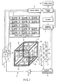
- the encapsulated medical device guidance system is roughly divided into a capsule endoscope 21 and a magnetic guidance device 1 that generates a magnetic field for inducing the capsule endoscope.
- the magnetic guidance device 1 includes, as its main components, guidance coil groups (X1, X2, Y1, Y2, Z1, Z2, D1, D2, D3, D4, D5, D6, D7, and D8), a guidance coil power source 2, a guidance control unite 3, a controller 4, a sensing coil unit 5 (5a to 5i), a position detector 6, a receiving antenna unit 7 (7a, 7b, and 7c), an antenna selector 8, a receiving unit 9, a display unit 10, a drive coil 11, and a drive-coil operating unit 12.
- guidance coil groups X1, X2, Y1, Y2, Z1, Z2, D1, D2, D3, D4, D5, D6, D7, and D8
- a guidance coil power source 2 includes, as its main components, guidance coil groups (X1, X2, Y1, Y2, Z1, Z2, D1, D2, D3, D4, D5, D6, D7, and D8), a guidance coil power source 2, a guidance control unite 3, a controller 4, a sensing coil unit 5 (5a to 5
- Each of the fourteen guidance coil groups (X1, X2, Y1, Y2, Z1, Z2, D1 to D8) has an air-core electromagnet and forms an induction magnetic field generation unit.
- Guidance coils according to the present embodiment are disposed on the sides of a rectangular parallelepiped. As indicated by the arrow in FIG. 1 , the direction in which the capsule endoscope 21 is moved forward or backward direction (or the direction to which the human body used as a sample moves) is assumed to correspond to the X-axis direction.
- the direction horizontally perpendicular to the X-axis is defined as Y-axial direction, and the direction vertically perpendicular to the X-axis (i.e., the direction of gravity), as Z-axial direction.
- the guidance coils X1 and X2 are placed oppositely around the surfaces of front and rear sides, forming magnetic lines of force in the X-axis direction, and becoming vertical to the X-axis direction.
- the guidance coil X1 side is assumed as a forward direction
- the guidance coil X2 side as a backward direction.
- movement from the guidance coil X2 to the guidance coil X1 refers to forward movement, and its reverse, backward movement.
- the guidance coils Y1 and Y2 are disposed opposite to each other along the perimeters of both side faces perpendicular to the Y-axis, and generate magnetic lines of force along the Y-axis.
- the guidance coils D3 and D7 are disposed on one of the side faces and inside the guidance coil Y1 so as to divide this face into two.
- the guidance coils D1 and D5 are disposed on the other (i.e., opposite) of the side faces and inside the guidance coil Y2 so as to divide this face into two.
- the guidance coils Z1 and Z2 are disposed opposite to each other along the perimeters of both upper and lower faces perpendicular to the Z-axis, and generate magnetic lines of force along the Z-axis.
- the guidance coils D4 and D8 are disposed on the upper face and inside the guidance coil Z1 so as to divide this face into two.
- the guidance coils D2 and D6 are disposed on the lower (i.e., opposite) face and inside the guidance coil Z2 so as to divide this face into two.
- the guidance coil Z1 side is assumed as an upward direction and, the guidance coil Z2 side, as a lower direction.
- movement from the guidance coil Z2 to the guidance coil Z1 refers to upward movement, and the reverse of it, downward movement.
- the guidance coil groups are supplied with, for example, an alternating current, thereby generating an alternating magnetic field.
- This alternating magnetic field includes one ore more components of a frequency near resonance frequency produced by a capacitor 33 and a coil (i.e., magnetic induction coil 31) (described below) disposed in the capsule endoscope 21.
- An alternating magnetic field generated by the drive coil 11 acts on the magnetic induction coil 31, thereby generating an induction current. Consequently, a magnetic field is generated from the magnetic induction coil.
- the induction magnetic field thus generated is detected by the plurality of sensing coils 5a to 5i, thereby producing a signal including position information, which will be transmitted to the position detector 6. Based on this signal, the position detecting device calculates the position of the capsule endoscope 21 and information about its position. The position and position information are transmitted to the guidance control unite 3, and used for calculation that determines a magnetic field to be generated by the guidance coil groups.
- the group of guidance coils X1, X2, Y1, Y2, Z1, Z2 and D1 to D8 constitutes first magnetic gradient generating means, which generates a magnetic gradient (first magnetic gradient) that acts on a magnet (magnetic substance) in the capsule endoscope 21, thereby moving the magnet forward/backward or upward/downward, or left/right, and pulling the magnet in a desired direction.
- the guidance coil Z1 When the guidance coil groups pull the capsule endoscope 21 in a desired direction by moving the capsule endoscope 21 upward, the guidance coil Z1 generates magnetic gradient (second magnetic gradient) that acts on the magnet in the capsule endoscope 21 so as to cancel force of moving the capsule endoscope 21 downward, exerted on account of the gravity. Thus, the guidance coil eliminates the effect of the gravity.
- the guidance coils D4 and D8 may be allowed to act in the same manner as the guidance coil Z1.
- This guidance coil Z1 constitutes second magnetic gradient generating means, which eliminates the effect of gravity acting on the capsule endoscope 21 being moved in a desired direction.
- the guidance coil Z2 when the guidance coil groups pull the capsule endoscope 21 in a desired direction by moving the capsule endoscope 21 downward, the guidance coil Z2 generates magnetic gradient that acts on the magnet in the capsule endoscope 21 so as to cancel buoyancy causing the capsule endoscope 21 to float.
- the guidance coil Z2 eliminates the effect of buoyancy.
- the guidance coils D2 and D6 may be allowed to act in the same manner as the guidance coil Z2.
- the pair of opposite guidance coils X1 and X2, the pair of Y1 and Y2, and the pair of Z1 and Z2 each generate a magnetic field in the same direction within a space surrounded by the guidance coils, thereby generating a uniform magnetic filed. If the guidance coils of each pair generate magnetic fields in directions opposite to each other, an inclined magnetic field can be generated.
- Driving, as necessity requires, the guidance coils D1 to D8 in the same manner as described above makes it possible to generate a highly uniform magnetic filed, gradient magnetic field or the like. Accordingly, the independent control of the fourteen guidance coils allows the generation of a magnetic field of a desired magnetic field intensity and of a desired magnetic gradient in a desired space.
- Such a configuration of the guidance coil groups enables the capsule endoscope 21 not only to move forward/backward, upward/downward, or leftward/rightward, but also to incline by means of the group of guidance coils X1, X2, Y1, Y2, Z1, Z2, and D1 to D8 in combinations.
- the capsule endoscope 21 can be put in an oblique position with its forward end pointing upward.
- These guidance coils are connected to the guidance coil power supply 2 that are independently driven. These guidance coil power supplies 2 are controlled by commands given by the guidance control unite 3, and suitably supply power to the corresponding guidance coils used to generate a desired magnetic field in a desired space.
- the nine sense amplifiers 5a - 5i composing the sensing coil group 5 are evenly disposed within a plane parallel to the side face on which the guidance coil Y1 is disposed, so as to ensure the accurate position and position of the capsule endoscope 21.
- the present embodiment exemplifies the case where a combination of the sensing coil group 5 and the drive coil 11 disposed opposite to each other detects a position along the Z-axis.
- the number of sensing coils be somewhat larger.
- the position detector 6 receives an instruction to specify a timing of detecting the information about a position from the guidance control unit 3, and drives the drive coil driver 12 based on the instruction.
- the drive-coil operating unit 12 supplies an alternating current to the drive coil 11, thereby producing a magnetic field.
- an induction magnetic field is generated by the capsule endoscope 21 located in the magnetic field.
- Each sensing coil of the sensing coil group 5 detects a signal based on the induction magnetic field generated by the capsule endoscope 21, and outputs the corresponding signal to the position detector 6.
- the position detector 6 creates, from the signal based on the induction magnetic field, information about the position and position of the capsule endoscope 21, and then outputs this information to the guidance control unite 3.
- the guidance control unite 3 determines the desired moving direction, and instructs the guidance coil power supply 2 to generate a magnetic field appropriate for such movement.
- the guidance coil power supply 2 cause the corresponding guidance coil groups X1, X2, Y1, Y2, Z1, Z2 and D1 to D8 to produce a current. Consequently, the magnetic field appropriate for the movement is generated by the guidance coil group, thus making it possible to smoothly induce the capsule endoscope 21.
- the controller 4 serves as an input device that specifies the moving direction or gradient of the capsule endoscope 21 by inclining an input operation part, such as a joystick, operated in a given direction by an operator.
- an input operation part such as a joystick
- various members such as a sight line input device, a touch panel, and buttons disposed so as to allow moving in all directions, can also be used as an input operation part for the controller 4.
- the guidance control unite 3 receives instruction signals from the controller 4, position and posture information from the position detector 6, and signals relating to the driven state of each guidance coil from the receiving unit 9, and then calculates a magnetic force (magnetic field) for moving the capsule endoscope 21 to a desired position.
- the guidance control unite 3 also calculates magnetic forces that must be produced by the guidance coil groups X1, X2, Y1, Y2, Z1, Z2 and D1 to D8 in order to generate the magnetic force.
- control unite 3 transmits commands to the corresponding guidance coil power sources.
- the guidance control unite 3 stops generation of the magnetic field. Simultaneously with this, during the communication period, the position detector 6 operates the drive coils 11 based on instruction from the guidance control unite, thereby capturing position information from the sensing coil group 5.
- Three receiving antennas 7 are connected to the receiving device via the antenna selector 8, which performs a selection operation. These receiving antennas 7 are: a receiving antenna 7a (AX) that receives information about the inside of a body together with image data, from the axial X direction; a receiving antenna 7b (AY) that receives information about the inside of the body from the axial direction Y; and a receiving antenna 7c (AZ) that receives information about the inside of the body from the axial direction Z.
- AX receiving antenna 7a
- AY receiving antenna 7b
- AZ receiving antenna 7c
- the antenna selector 8 selects the antenna 7a, 7b, or 7c to be used for communication.
- the antenna selector 8 receives the intensity and direction of a magnetic field generated in the place of each receiving antenna by the guidance coil group, and the degree of a magnetic field gradient; distinguishes the receiving antenna that is least affected by the magnetic field from the other antennas; and selects this receiving antenna. Selecting this receiving antenna 7 stabilizes communications between the capsule endoscope 21 and receiving unit 9.
- a signal indicating the timing of receiving information about the inside of a body from the capsule endoscope 21 is transmitted to the guidance control unite 3 by the receiving unit 9.
- the guidance control unite 3 stops the guidance coil group and drive coil 11 from generating an induction magnetic field during the communication period, which is the period during which information about the inside of the body (image data) is transmitted.
- This stopping process makes it possible for the receiving device to receive information about the inside of a body from the capsule endoscope 21 without being affected by an induction magnetic field.
- This stopping process prevents the communication period from coinciding with a moving period and position detecting period. Accordingly, this eliminates the effects of noise upon the information about the inside of a body and of an induction magnetic field upon the receiving antennas.
- this stopping process is effective in preventing noise from affecting image data and also in eliminating the effect of an induction magnetic field on the receiving antennas. Even in the case where the intensity of a magnetic field generated from any of the guidance coils is high, the position detector 6 can be properly operated.
- the display unit 10 consists of a liquid crystal display, and displays an image generated by the receiving unit 9 and shot by the capsule endoscope 21.
- the data such as imaging situation related to the displayed image may be displayed on the screen together with the image.
- FIG. 2 is a sectional view of the configuration of the capsule endoscope according to the present embodiment.
- a capsule container 23 of the capsule endoscope 21 includes: a transparent semispherical leading-end container 23a on the front end side; and an infrared-transparent trailing-end container 23b with an exactly cylindrical shape becoming semispherical towards the trailing end.
- the capsule container 23 accommodates a capsule endoscope body (described below) and is closed tightly so as to be impervious to water.
- the direction in which the capsule container 21 is propelled is, for example, in the axial direction of the cylinder, as indicated by reference letter C in FIG. 2 .
- the capsule endoscope body will now be described.
- the capsule endoscope body is roughly divided into: an imaging unit for imaging the medial wall of an intracavital; a power source unit for driving the imaging unit; an induction magnetic field generation unit for generating an induction magnetic field by means of the drive coil 11 described above; a drive magnet for driving the capsule endoscope 21; and a transmission unit for transmitting information (communication data) about the inside of a body to the receiving antennas 7 together with the data of the image picked up.
- the imaging unit includes: imaging optics 26 having a fixed focusing lens; an imaging element 25 composed of a CMOS, a CCD, etc., mounted on an imaging-side substrate 24a; an illuminating unit 39 disposed near the imaging optics 26 and having LEDs the light from which can be modulated; and an image processing circuit 27 disposed on the back of the imaging-side substrate 24a relative to the imaging element 25 and used to subject an image signal from the imaging element 25 to a predetermined imaging process.
- the imaging-side substrate 24a, a power-source-side substrate 24b, and a front battery-substrate 43a are integrally fixed by being sealed in a bonding unit 29 with an adhesive.
- the power source unit includes: a small battery 32 composed of a button battery or the like; a pair of battery-side substrates 43 (43a, 43b) provided with a power source terminal (not shown) that derives power from the small battery 32; a heat-shrinkable tube 34 fixing the small battery 32 between the battery substrates; the power-source-side substrate 24b, the circuit wiring of which is electrically connected to the circuit wiring of the imaging-side substrate 24a by means of a flexible substrate or the like; and a power source circuit 28 disposed on the power-source-side substrate 24b and supplied with the power of the small battery 32.
- the magnetic field generation unit includes: a magnet 30 disposed on the perimeter of the bonding unit 29; a magnetic induction coil 31 disposed via the magnet 30; and a capacitor 33 disposed on the battery substrate on the front end side and composing a CL resonance circuit together with the induction coil 31.
- This magnetic induction coil 31 is formed in the shape of a ring of the maximum outside shape slightly smaller than the inside diameter of the capsule container 23.
- the magnet 30 causes external magnetic fields to converge onto the magnetic induction coil 31.
- Examples of the material of the magnet 30 are an amorphous magnetic body and FINE MED (manufactured by Hitachi Metals, Ltd.), which are high in saturated magnetic flux density and magnetic permeability. Such a material formed in a thin film is effective to reduce the volume of the magnet disposed in the capsule endoscope.
- a disk-shaped driving magnet 42 disposed on the rear battery-substrate 43b is a disk-shaped driving magnet 42.
- a preferred example of the material for the magnet 42 is neodymium cobalt but the material is not limited to this.
- the upper and lower portions of the magnet 42 are polarized N and S respectively so that lines of magnetic force are generated along the Z-axis. Setting the polarities in this manner makes it possible always to orient the capsule endoscope 21 in a fixed direction in relation to the guidance coil groups of the magnetic guidance device 1. Accordingly, the top and bottom of an image picked up can be absolutely determined.
- the transmission unit includes: a transmission circuit 36 mounted on the back (magnet 42 side) of a transmission substrate 40; an antenna 37 disposed on the surface (rear-end container 23b) of the substrate 40; a shield part 35 that covers an exposed transmission circuit 36 and confines the magnetic force of the magnet 42; and an optical switch 38 mounted on the antenna 37 side of the transmission substrate 40 and used to turn the capsule endoscope on or off.
- the direction in which the polarities of the magnet 42 are set and the direction of the antenna 37 connected to the transmission circuit 36 are made different by 90° in order to satisfy conditions for making the entry direction of a magnetic field generated by the magnet 42 different from the direction of the antenna 37 by 90°.
- the effect of magnet 42's field on the antenna 37 is minimized.
- the shield part 35 is made of a magnetic material and absorbs magnetic fields near the antenna 37. This reduces the intensity of any magnetic field entering the antenna 37, and minimizes the effect of a magnetic field on radio communication between the transmission circuit 36 and antenna 37, and thus ensuring stable radio communication.
- the optical switch 38 senses infrared rays and the like. At least part of the trailing-end container 23b of the capsule container 23, which part is near the optical switch, is made of a material that transmits infrared rays (of a wavelength sensitive to the optical switch). By emitting infrared rays onto the optical switch 38 from an infrared ray emitting device (not shown), the optical switch 38 should be turned on, power is then supplied to the capsule endoscope from the small battery 32 via the power source circuit, and the capsule endoscope is consequently activated to initiate an imaging process and a transmission process. This circuit of the optical switch 38 is configured to allow a toggle operation.
- the capsule endoscope maintains an on-state.
- the circuit of the optical switch 38 may be configured such that the capsule endoscope is turned off by re-emitting infrared rays onto the optical switch when the switch is in the on-state.
- the shield part 35 covering the transmission circuit 36 minimizes the effect of the intensity of magnet 42's magnetic field on the transmission circuit and radio circuit (e.g., superposed noises or a shorter communicative distance). Thus, sharper image data with less noise can be transmitted to the receiving unit 9.
- magnetic fields with magnetic gradients are superposed, thereby generating one magnetic field, which moves the capsule endoscope 21.
- the magnetic field intensity or magnetic gradient for inducing the capsule endoscope 21 are very large, compared to an electric wave (electromagnetic wave) corresponding to information about the inside of the body transmitted by the capsule endoscope 21. If a signal exceeding the input allowable range of the receiving elements (e.g., preamplifier) of the receiving unit 9 is transmitted and an induction current is applied, the receiving elements can be damaged.
- the capsule endoscope 21 may suddenly move. Consequently, considerable induced voltage may be produced in the coil forming the transmission antenna 37 of the capsule endoscope 21, resulting in a severe overload being applied to the transmission circuit. Even if the overload does not go beyond the electrical resistance of the components, radio communication may fail.
- the present embodiment selectively disconnects any receiving antenna of the magnetic guidance device 1, which has been affected by a magnetic field inducing the capsule endoscope 21, or in which an overload current caused by induced voltage is flowing.
- a description will be given of the configuration of a circuit that includes the function of preventing overload current, caused by induced voltage arising from a sudden movement of the capsule endoscope 21 or sudden change in magnetic field gradient, from being applied to the transmission circuit 36 of the capsule endoscope 21 and the receiving unit 9 of the magnetic field generation device 1.
- the magnetic guidance device 1 includes three receiving antennas 7 (AX, AY, and AZ) that have directions of highest sensitivity along the axes X, Y, and Z respectively, as shown in FIG. 1 .
- the description below exemplifies the relation between the guidance coil Y2 and the receiving antennas 7 (AX, AY, and AZ).
- Lines of magnetic force generated by the guidance coil Y2 supplied with power pass the receiving antennas AX, AY, and AZ, as shown in FIG. 3 .
- lines of magnetic force are parallel to the direction in which the sensitivity is highest of this antenna.
- an overload current may flow in the receiving antenna AY on account of induced voltage caused by a magnetic field generated by the guidance coil Y2.
- Lines of magnetic force enter the other receiving antennas AX and AZ at approximately 90° relative to their respective directionalities, as shown in FIG. 3 .
- the receiving antenna subjected to the most intense induced voltage by a magnetic field on account of the direction of highest sensitivity of the receiving antenna is distinguished from the others, and the one ensuring accurate receiving can be selected.
- the antenna selector 8 is provided for antenna selection.
- the receiving antennas AX and AX allow accurate receiving, either one of them is selected, thus making it possible to receive information about the inside of a body together with accurate image data from the capsule endoscope 21.
- This embodiment exemplifies the case where three receiving antennas are disposed so as to have directionalities along the three axes perpendicular to one another.
- the invention is not limited to this and, even if the receiving antennas are oriented in the same direction, similar control can be achieved by taking the directions of lines of magnetic force into consideration.
- FIG. 4 shows a modified example in which three receiving antennas 7 (AY1, AY2 and AY3) are disposed in the same direction.
- the receiving antenna AY2 is disposed in the middle of the three and right opposite to the middle of the guidance coil Y2. On account of this positional relation, the direction of highest sensitivity of the receiving antenna AY2, in which receiver sensitivity is highest, coincides with the direction of lines of magnetic force of a magnetic field generated by the guidance coil Y2.
- an overload current caused by the induced voltage of the guidance coil Y2 may flow to excess in the receiving antenna AY2, leading to failure in communication with the capsule endoscope 21.
- the receiving antennas AY1 and AY3 receive lines of magnetic force from oblique directions, thus restraining overload currents caused by induced voltage, and hence ensuring accurate receiving of information about the inside of a body from the capsule endoscope 21.
- Arranging the plural receiving antennas 7 along the same axis at arbitrary intervals and selecting a suitable one from them makes it possible constantly to receive accurate information about the inside of a body transmitted from the capsule endoscope 21.
- the receiving antennas are evaluated based on the direction and intensity of the magnetic field. Normal communication can be maintained by selecting the receiving antenna into which a line of magnetic force enters at an angle closest to 90° relative to the direction of highest sensitivity of the receiving antenna. In order to select a preferred receiving antenna, it is preferable that the intensity of and rate of change in a magnetic field generated in proximity to each receiving antenna be evaluated taking the entry direction of the magnetic field into consideration.
- An overload current I caused by induced voltage is defined by a relation expressed by the following formula: I ⁇ (dH/dt) ⁇ cos( ⁇ ), wherein H represents the intensity of a magnetic field generated by a plurality of magnetic field generating devices in proximity to a receiving antenna, and ⁇ represents an angle between the magnetic field and the direction of highest sensitivity of the receiving antenna.
- the dH/dt represents the rate of change in the magnetic field.
- H can be used as substantially equivalent to dH/dt.
- the intensity of the magnetic field to be generated by each guidance coil power source 2 is determined.
- the intensity of the magnetic field (the rate of change in the magnetic field) generated in proximity to each receiving antenna 7 and the direction of the magnetic field are obtained.
- a coefficient proportional to an induction current flowing in each receiving antenna 7 is obtained.
- the angle between the direction of highest sensitivity of each receiving antenna and the magnetic field is obtained.
- the antenna selector 8 selects the receiving antenna with the smallest coefficient proportional to an induction current (an overload current caused by induced voltage). Alternatively, the antenna selector 8 selects the receiving antenna in which the angle between the direction of highest sensitivity and the magnetic field is closest to 90°.
- the antenna selector 8 selects the receiving antenna least subjected to the application of overload current caused by induced voltage generated by an guidance coil in order to perform position guidance or position control for the capsule endoscope, as described above.
- FIG. 5 shows a first example in which a Zener diode array (a series of Zener diodes) 51 is inserted between both ends of a coil forming the transmission antenna 37 of the capsule endoscope 21.
- a Zener diode array 51 a series of Zener diodes
- the anodes of the two Zener diodes are connected so as to cope with an alternating current signal, and their cathodes are connected to the corresponding ends of the coil 37.
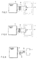
- FIG. 6 shows a second example in which a lead switch 52 is inserted between both ends of the coil forming the transmission antenna 37 of the capsule endoscope 21.
- the lead switch 52 is turned on and consequently a current flows into it. This makes it possible to limit the flow of current into the transmission circuit 36 and hence prevent damage to the circuit.
- the induced voltage is not directly monitored. However, when a greater induced voltage is caused, a greater magnetic field is usually generated and accordingly, effects may occur similar to those in the first example.
- FIG. 7 shows a third example in which a Zener diode array (a series of Zener diodes) 54 is inserted between both ends of each receiving antenna 7 (AY1, AY2, AY3) of the receiving unit 9.
- the receiving antennas 7 are connected to the input terminal of the receiving unit 9 via a transformer 53.
- the Zener diode array 54 the two anodes of the Zener diodes are connected, and their cathodes are connected to the corresponding ends of the receiving antennas 7.
- the input and output of the transformer 53 are electrically equivalent.
- FIG. 8 shows a fourth example in which a lead switch 55 is inserted between both ends of each receiving antenna 7 (AY1, AY2, AY3) of the receiving unit 9. If a magnetic field reaches or exceeds a prescribed threshold, a lead switch is turned on and, consequently, an overload current caused by induced voltage flows through the lead switch 55. This limits the current flowing into the receiving unit 9 and prevents damage thereto.
- the induced voltage is not directly monitored. However, when a greater induced voltage is caused, a greater magnetic field is usually generated and accordingly, effects may occur similar to those in the third example.
- FIG. 9 shows a fifth example in which a ⁇ /4 stub line 61 is inserted into the input line of the receiving unit 9 connected to each receiving antenna 7 (AY1, AY2, AY3) via a transformer 56.
- the input and output of the transformer 56 are electrically equivalent.
- ⁇ /4 stub line 61 if a short circuit (potential grounding) is formed at one end of it with a ⁇ /4 stub of a transmission line in relation to a wavelength ⁇ used in a radio circuit, the other end is open.
- the radio circuit operated at ⁇ is not affected at all, and the other frequencies are short-circuited. If the component of the frequency corresponding to a sudden change in a magnetic field does not reach the frequency of radio communication, a voltage surge can be avoided by this ⁇ /4 stub line 61. Therefore, if induced electromagnetic force arises, overload current flowing in the input line is caused to flow into an installation and, thus, damage to the receiving unit 9 is prevented.
- FIG. 10 is a sixth example in which a ⁇ /4 stub line 62 is inserted between both ends of the transmission antenna 37 of the transmission circuit 36. Since the ⁇ /4 stub line 62 identical to that in the fifth example is provided, overload current caused by induced voltage is short-circuited. This limits the current flowing into the transmission circuit 36 and prevents damage to the transmission circuit 36.
- the present invention can, therefore, provide an encapsulated medical device guidance system which includes a plurality of receiving antennas of different directionalities and selects a receiving antenna appropriate to receive information about the inside of a body transmitted from an encapsulated medical device.
Landscapes
- Health & Medical Sciences (AREA)
- Life Sciences & Earth Sciences (AREA)
- Surgery (AREA)
- Engineering & Computer Science (AREA)
- General Health & Medical Sciences (AREA)
- Molecular Biology (AREA)
- Pathology (AREA)
- Veterinary Medicine (AREA)
- Public Health (AREA)
- Biophysics (AREA)
- Biomedical Technology (AREA)
- Heart & Thoracic Surgery (AREA)
- Medical Informatics (AREA)
- Physics & Mathematics (AREA)
- Animal Behavior & Ethology (AREA)
- Optics & Photonics (AREA)
- Nuclear Medicine, Radiotherapy & Molecular Imaging (AREA)
- Radiology & Medical Imaging (AREA)
- Computer Networks & Wireless Communication (AREA)
- Human Computer Interaction (AREA)
- Endoscopes (AREA)
- Measurement Of The Respiration, Hearing Ability, Form, And Blood Characteristics Of Living Organisms (AREA)
Claims (13)
- System (1, 21) zum Führen einer kapselförmigen Medizinvorrichtung mit:einer kapselförmigen Medizinvorrichtung (21), die eine Erfassungseinheit (25) für innere biologische Informationen zum Gewinnen innerer biologischer Informationen, eine Kommunikationseinheit (36) zum Ausgeben der gewonnenen inneren biologischen Informationen als Ausgangssignal nach außen und einen Magneten (42) aufweist;einer Vielzahl von Empfangsantennen (7a-7c), die sich in der Richtung der höchsten Empfängerempfindlichkeit voneinander unterscheiden und dazu ausgebildet sind, das Ausgangssignal zu empfangen;einem Auswahlschalter (8), der mit Ausgangssignalwegen der Vielzahl von Antennen (7a-7c) verbunden und dazu ausgebildet ist, irgendeinen der Ausgangssignalwege durch Umschalten auszuwählen;einer Empfangsvorrichtung (9), die mit dem Auswahlschalter (8) verbunden und dazu ausgebildet ist, das Signal von dem ausgewählten Ausgangssignalweg der Empfangsantenne zu empfangen;einem Controller (4), der dazu ausgebildet ist, eine gewünschte Bewegungsrichtung der kapselförmigen Medizinvorrichtung (21) anzuweisen;einer Magnetfeld-Erzeugungseinheit (X1, X2, Y1, Y2, Z1, Z2, D1-D8), die ein Induktionsmagnetfeld erzeugen kann, das auf den Magnet (42) der kapselförmigen Medizinvorrichtung einwirkt, um die kapselförmige Medizinvorrichtung in die angewiesene Zielrichtung zu bewegen; undeiner Steuereinheit (3), die dazu ausgebildet ist, ein Anweisungssignal vom Controller (4) zu empfangen und eine Betätigung der Magnetfeld-Erzeugungseinheit (X1, X2, Y1, Y2, Z1, Z2, D1-D8) zu steuern,dadurch gekennzeichnet, dass die Steuereinheit (3) dazu ausgebildet ist, auf der Grundlage der Signalausgabe von der Empfangsvorrichtung (9) eine Empfangsantenne zu ermitteln, in welcher durch das Führungsmagnetfeld ein Überlaststrom fließt, und den Auswahlschalter (8) so zu steuern, dass er einen Ausgangssignalweg der ermittelten Empfangsantenne von der Empfangsvorrichtung (9) trennt.
- System nach Anspruch 1, wobei die Steuereinheit (3) dazu ausgebildet ist, einen Winkel zwischen der Richtung des durch die Magnetfeld-Erzeugungseinheit (X1, X2, Y1, Y2, Z1, Z2, D1-D8) erzeugten Induktionsmagnetfelds und der Richtung zu berechnen, in welcher die Empfängerempfindlichkeit jeder Empfangsantenne (7a-7c) am höchsten ist,
auf der Grundlage des Berechnungsergebnisses eine Empfangsantenne auszuwählen, von der festgestellt wird, dass sie die am wenigsten parallele ist, und diese Antenne mit der Empfangsvorrichtung (9) zu verbinden. - System nach Anspruch 1, wobei ein magnetischer Anschluss-Schalter mit beiden Anschlüssen oder elektrisch äquivalenten Anschlüssen der Empfangsantennen (7a-7c) verbunden ist.
- System nach Anspruch 1, wobei ein Zener-Diodenarray (54) mit beiden Anschlüssen oder elektrisch äquivalenten Anschlüssen der Empfangsantennen (7a-7c) verbunden ist.
- System nach Anspruch 1, wobei eine aus einer Übertragungsleitung gebildete kurze Stichleitung mit beiden Anschlüssen oder elektrisch äquivalenten Anschlüssen der Empfangsantenne verbunden ist.
- System nach Anspruch 1, wobei die Kommunikationseinheit (36) eine Sendeantenne (37) aufweist und ein magnetischer Anschluss-Schalter mit beiden Anschlüssen oder elektrisch äquivalenten Anschlüssen der Sendeantenne verbunden ist.
- System nach Anspruch 1, wobei die Kommunikationseinheit (36) eine Sendeantenne (37) aufweist und ein Zener-Diodenarray mit beiden Anschlüssen oder elektrisch äquivalenten Anschlüssen der Sendeantenne (37) verbunden ist.
- System nach Anspruch 1, wobei die Kommunikationseinheit (36) eine Sendeantenne (37) aufweist und eine aus einer Übertragungsleitung gebildete kurze Stichleitung mit beiden Anschlüssen oder elektrisch äquivalenten Anschlüssen der Sendeantenne verbunden ist.
- System nach Anspruch 1, wobei die Kommunikationseinheit (36) ein Abschirmungsteil (35) besitzt, das aus einem magnetischen Material besteht.
- System zum Führen einer kapselförmigen Medizinvorrichtung nach Anspruch 1, das ferner aufweist:einen Positionsdetektor (6), der dazu ausgebildet ist, um die kapselförmige Medizinvorrichtung (21) herum ein Magnetfeld auszubilden und Positionsinformationen aus einem Führungsmagnetfeld zu ermitteln, welches durch die kapselförmige Medizinvorrichtung (21) erzeugt wird; wobeidie Steuereinheit (3) dazu ausgebildet ist, während eines Kommunikationszeitraums, in dem die durch die kapselförmige Medizinvorrichtung (21) gewonnenen inneren biologischen Informationen zur Empfangsvorrichtung (9) gesendet werden, die Erzeugung des Führungsmagnetfelds anzuhalten und die Positionsinformationen zu gewinnen.
- System nach Anspruch 10, wobei das Antennensteuerelement ein magnetischer Anschluss-Schalter ist.
- System nach Anspruch 10, wobei das Antennensteuerelement ein Zener-Diodenarray (54) ist.
- System nach Anspruch 10, wobei das Antennensteuerelement eine aus einer Übertragungsleitung gebildete kurze Stichleitung (61) ist.
Applications Claiming Priority (2)
| Application Number | Priority Date | Filing Date | Title |
|---|---|---|---|
| JP2005375538A JP4827525B2 (ja) | 2005-12-27 | 2005-12-27 | カプセル型医療装置誘導システム |
| PCT/JP2006/326147 WO2007074887A1 (ja) | 2005-12-27 | 2006-12-27 | カプセル型医療装置誘導システム及びその制御方法 |
Publications (3)
| Publication Number | Publication Date |
|---|---|
| EP1972254A1 EP1972254A1 (de) | 2008-09-24 |
| EP1972254A4 EP1972254A4 (de) | 2009-09-09 |
| EP1972254B1 true EP1972254B1 (de) | 2014-03-19 |
Family
ID=38218109
Family Applications (1)
| Application Number | Title | Priority Date | Filing Date |
|---|---|---|---|
| EP06843529.6A Expired - Fee Related EP1972254B1 (de) | 2005-12-27 | 2006-12-27 | System zur führung eines kapselförmigen medizinprodukts |
Country Status (5)
| Country | Link |
|---|---|
| US (1) | US8337396B2 (de) |
| EP (1) | EP1972254B1 (de) |
| JP (1) | JP4827525B2 (de) |
| CN (1) | CN101351142B (de) |
| WO (1) | WO2007074887A1 (de) |
Families Citing this family (17)
| Publication number | Priority date | Publication date | Assignee | Title |
|---|---|---|---|---|
| JP5340566B2 (ja) * | 2007-07-24 | 2013-11-13 | オリンパスメディカルシステムズ株式会社 | 受信装置 |
| EP2567653B1 (de) * | 2008-06-19 | 2014-09-03 | Olympus Medical Systems Corp. | Magnetisches Führungssystem |
| DE102008049198B4 (de) * | 2008-09-26 | 2017-03-02 | Siemens Healthcare Gmbh | Spulensystem, medizinisches Gerät und Verfahren zur berührungslosen magnetischen Navigation eines magnetischen Körpers in einem Arbeitsraum |
| JP2010110432A (ja) * | 2008-11-05 | 2010-05-20 | Olympus Corp | 無線型被検体内情報取得装置 |
| WO2010103866A1 (ja) * | 2009-03-10 | 2010-09-16 | オリンパスメディカルシステムズ株式会社 | 位置検出システムおよび位置検出方法 |
| DE102009060608A1 (de) * | 2009-12-23 | 2011-06-30 | Siemens Aktiengesellschaft, 80333 | Spulensystem und Verfahren zur berührungslosen magnetischen Navigation eines magnetischen Körpers in einem Arbeitsraum |
| DE102009060514A1 (de) * | 2009-12-23 | 2011-06-30 | Siemens Aktiengesellschaft, 80333 | Spulensystem und Verfahren zur berührungslosen magnetischen Navigation eines magnetischen Körpers in einem Arbeitsraum |
| WO2012124228A1 (ja) | 2011-03-15 | 2012-09-20 | オリンパスメディカルシステムズ株式会社 | 医療装置 |
| US9526080B2 (en) * | 2011-03-22 | 2016-12-20 | Given Imaging Ltd. | Systems and methods for synchronizing between an in-vivo device and a localization system |
| CN103784144B (zh) * | 2012-10-30 | 2015-10-21 | 上海理工大学 | 多磁场源的正弦交变磁场发生装置 |
| CN103340595B (zh) * | 2013-07-03 | 2015-08-26 | 安翰光电技术(武汉)有限公司 | 一种无线胶囊内窥镜及其电源控制方法 |
| JP2015123334A (ja) * | 2013-12-27 | 2015-07-06 | オリンパス株式会社 | 無線送信器及び生体情報取得システム |
| WO2016092941A1 (ja) * | 2014-12-12 | 2016-06-16 | オリンパス株式会社 | カプセル内視鏡システム及びその撮像方法 |
| CN107405052B (zh) * | 2016-03-04 | 2019-03-26 | 奥林巴斯株式会社 | 引导装置以及胶囊型医疗装置引导系统 |
| US11756716B2 (en) * | 2016-08-10 | 2023-09-12 | Iucf-Hyu (Industry-University Cooperation | Magnetic field control system |
| US10404093B2 (en) * | 2017-04-26 | 2019-09-03 | Biosense Webster (Israel) Ltd. | Using location transmission signals for charging a wireless medical tool of an electromagnetic navigation system |
| CN112294240A (zh) * | 2019-07-25 | 2021-02-02 | 北京微纳灵动科技有限公司 | 胶囊机器人的磁控方法 |
Family Cites Families (15)
| Publication number | Priority date | Publication date | Assignee | Title |
|---|---|---|---|---|
| US5681260A (en) * | 1989-09-22 | 1997-10-28 | Olympus Optical Co., Ltd. | Guiding apparatus for guiding an insertable body within an inspected object |
| DE19745310C2 (de) * | 1997-10-14 | 1999-10-21 | Temic Semiconductor Gmbh | Modulationsverfahren zur Datenübertragung von einem Transponder zu einem Schreib-Lese-Gerät sowie eine Anordnung zur Durchführung des Modulationsverfahrens |
| JP3974769B2 (ja) * | 2001-11-06 | 2007-09-12 | オリンパス株式会社 | カプセル型医療装置 |
| JP2004167163A (ja) * | 2002-11-22 | 2004-06-17 | Olympus Corp | カプセル型医療システム |
| JP4091004B2 (ja) | 2003-02-04 | 2008-05-28 | オリンパス株式会社 | 医療装置誘導システム |
| JP4153845B2 (ja) * | 2003-08-11 | 2008-09-24 | オリンパス株式会社 | 医療装置誘導システム |
| DE10343494B4 (de) | 2003-09-19 | 2006-06-14 | Siemens Ag | Magnetisch navigierbare Einrichtung für den Einsatz auf dem Gebiet der medizinischen Endoskopie |
| JP4414725B2 (ja) * | 2003-10-28 | 2010-02-10 | オリンパス株式会社 | カプセル型医療装置 |
| US7751866B2 (en) * | 2004-03-08 | 2010-07-06 | Olympus Corporation | Detecting system of position and posture of capsule medical device |
| JP4009617B2 (ja) * | 2004-05-26 | 2007-11-21 | オリンパス株式会社 | 位置関係検出装置および位置関係検出システム |
| JP2006075533A (ja) * | 2004-09-13 | 2006-03-23 | Olympus Corp | 被検体内導入システム、受信装置および被検体内導入装置 |
| KR100972253B1 (ko) * | 2004-12-17 | 2010-07-23 | 올림푸스 가부시키가이샤 | 자기 유도를 이용한 의료용 위치 검출 시스템 |
| KR100909308B1 (ko) * | 2005-01-21 | 2009-07-24 | 올림푸스 가부시키가이샤 | 무선형 피검체내 정보 취득 시스템 |
| CN1647749A (zh) * | 2005-02-03 | 2005-08-03 | 重庆金山科技(集团)有限公司 | 双工多通道智能胶囊无线内窥镜系统 |
| CN1709196A (zh) * | 2005-02-08 | 2005-12-21 | 重庆金山科技(集团)有限公司 | 双工多通道智能胶囊消化道内窥镜的控制方法 |
-
2005
- 2005-12-27 JP JP2005375538A patent/JP4827525B2/ja not_active Expired - Fee Related
-
2006
- 2006-12-27 WO PCT/JP2006/326147 patent/WO2007074887A1/ja active Application Filing
- 2006-12-27 EP EP06843529.6A patent/EP1972254B1/de not_active Expired - Fee Related
- 2006-12-27 CN CN2006800496284A patent/CN101351142B/zh active Active
-
2008
- 2008-06-26 US US12/146,725 patent/US8337396B2/en active Active
Also Published As
| Publication number | Publication date |
|---|---|
| JP2007175188A (ja) | 2007-07-12 |
| US20080300459A1 (en) | 2008-12-04 |
| US8337396B2 (en) | 2012-12-25 |
| EP1972254A1 (de) | 2008-09-24 |
| CN101351142A (zh) | 2009-01-21 |
| JP4827525B2 (ja) | 2011-11-30 |
| CN101351142B (zh) | 2010-08-18 |
| EP1972254A4 (de) | 2009-09-09 |
| WO2007074887A1 (ja) | 2007-07-05 |
Similar Documents
| Publication | Publication Date | Title |
|---|---|---|
| EP1972254B1 (de) | System zur führung eines kapselförmigen medizinprodukts | |
| JP2007175188A5 (de) | ||
| EP2384687B1 (de) | System zum Führen einer verkapselten medizinischen Vorrichtung | |
| US20130331649A1 (en) | Magnetically maneuverable in-vivo device | |
| JP6351756B2 (ja) | カプセル内視鏡検査装置 | |
| JP5030392B2 (ja) | 医療装置の位置検出システムおよび医療装置誘導システム | |
| KR100889160B1 (ko) | 자기 안내 의료 장치 | |
| EP1955644B1 (de) | System zum nachweis der position eines medizinprodukts, führungssystem für ein medizinprodukt und verfahren zum nachweis der position eines medizinprodukts | |
| US20110181273A1 (en) | Position detecting system and position detecting method | |
| CN102283652A (zh) | 磁性引导系统 | |
| JP2009521977A (ja) | 生体内磁気位置決定システムおよび方法 | |
| JP2008054774A (ja) | カプセル誘導システム | |
| US20180353056A1 (en) | Optical fiber scanning system and endoscope system |
Legal Events
| Date | Code | Title | Description |
|---|---|---|---|
| PUAI | Public reference made under article 153(3) epc to a published international application that has entered the european phase |
Free format text: ORIGINAL CODE: 0009012 |
|
| 17P | Request for examination filed |
Effective date: 20080723 |
|
| AK | Designated contracting states |
Kind code of ref document: A1 Designated state(s): DE FR GB |
|
| DAX | Request for extension of the european patent (deleted) | ||
| RBV | Designated contracting states (corrected) |
Designated state(s): DE FR GB |
|
| A4 | Supplementary search report drawn up and despatched |
Effective date: 20090806 |
|
| RTI1 | Title (correction) |
Free format text: ENCAPSULATED MEDICAL DEVICE GUIDING SYSTEM |
|
| 17Q | First examination report despatched |
Effective date: 20110928 |
|
| GRAP | Despatch of communication of intention to grant a patent |
Free format text: ORIGINAL CODE: EPIDOSNIGR1 |
|
| INTG | Intention to grant announced |
Effective date: 20131014 |
|
| GRAS | Grant fee paid |
Free format text: ORIGINAL CODE: EPIDOSNIGR3 |
|
| GRAA | (expected) grant |
Free format text: ORIGINAL CODE: 0009210 |
|
| AK | Designated contracting states |
Kind code of ref document: B1 Designated state(s): DE FR GB |
|
| REG | Reference to a national code |
Ref country code: GB Ref legal event code: FG4D |
|
| REG | Reference to a national code |
Ref country code: DE Ref legal event code: R096 Ref document number: 602006040785 Country of ref document: DE Effective date: 20140430 |
|
| REG | Reference to a national code |
Ref country code: DE Ref legal event code: R097 Ref document number: 602006040785 Country of ref document: DE |
|
| PLBE | No opposition filed within time limit |
Free format text: ORIGINAL CODE: 0009261 |
|
| STAA | Information on the status of an ep patent application or granted ep patent |
Free format text: STATUS: NO OPPOSITION FILED WITHIN TIME LIMIT |
|
| 26N | No opposition filed |
Effective date: 20141222 |
|
| REG | Reference to a national code |
Ref country code: DE Ref legal event code: R097 Ref document number: 602006040785 Country of ref document: DE Effective date: 20141222 |
|
| GBPC | Gb: european patent ceased through non-payment of renewal fee |
Effective date: 20141227 |
|
| REG | Reference to a national code |
Ref country code: FR Ref legal event code: ST Effective date: 20150831 |
|
| PG25 | Lapsed in a contracting state [announced via postgrant information from national office to epo] |
Ref country code: GB Free format text: LAPSE BECAUSE OF NON-PAYMENT OF DUE FEES Effective date: 20141227 |
|
| REG | Reference to a national code |
Ref country code: DE Ref legal event code: R082 Ref document number: 602006040785 Country of ref document: DE Representative=s name: WUESTHOFF & WUESTHOFF, PATENTANWAELTE PARTG MB, DE Ref country code: DE Ref legal event code: R081 Ref document number: 602006040785 Country of ref document: DE Owner name: OLYMPUS CORPORATION, JP Free format text: FORMER OWNER: OLYMPUS MEDICAL SYSTEMS CORP., TOKIO/TOKYO, JP |
|
| PG25 | Lapsed in a contracting state [announced via postgrant information from national office to epo] |
Ref country code: FR Free format text: LAPSE BECAUSE OF NON-PAYMENT OF DUE FEES Effective date: 20141231 |
|
| PGFP | Annual fee paid to national office [announced via postgrant information from national office to epo] |
Ref country code: DE Payment date: 20151222 Year of fee payment: 10 |
|
| REG | Reference to a national code |
Ref country code: DE Ref legal event code: R119 Ref document number: 602006040785 Country of ref document: DE |
|
| PG25 | Lapsed in a contracting state [announced via postgrant information from national office to epo] |
Ref country code: DE Free format text: LAPSE BECAUSE OF NON-PAYMENT OF DUE FEES Effective date: 20170701 |