EP1969346B1 - Apparatus and method for on-line detecting welding part of strip - Google Patents
Apparatus and method for on-line detecting welding part of strip Download PDFInfo
- Publication number
- EP1969346B1 EP1969346B1 EP06768643.6A EP06768643A EP1969346B1 EP 1969346 B1 EP1969346 B1 EP 1969346B1 EP 06768643 A EP06768643 A EP 06768643A EP 1969346 B1 EP1969346 B1 EP 1969346B1
- Authority
- EP
- European Patent Office
- Prior art keywords
- laser beam
- steel strip
- weld
- reflectivity
- line detection
- Prior art date
- Legal status (The legal status is an assumption and is not a legal conclusion. Google has not performed a legal analysis and makes no representation as to the accuracy of the status listed.)
- Active
Links
Images




Classifications
-
- G—PHYSICS
- G01—MEASURING; TESTING
- G01N—INVESTIGATING OR ANALYSING MATERIALS BY DETERMINING THEIR CHEMICAL OR PHYSICAL PROPERTIES
- G01N21/00—Investigating or analysing materials by the use of optical means, i.e. using sub-millimetre waves, infrared, visible or ultraviolet light
- G01N21/17—Systems in which incident light is modified in accordance with the properties of the material investigated
- G01N21/47—Scattering, i.e. diffuse reflection
-
- G—PHYSICS
- G01—MEASURING; TESTING
- G01N—INVESTIGATING OR ANALYSING MATERIALS BY DETERMINING THEIR CHEMICAL OR PHYSICAL PROPERTIES
- G01N21/00—Investigating or analysing materials by the use of optical means, i.e. using sub-millimetre waves, infrared, visible or ultraviolet light
- G01N21/17—Systems in which incident light is modified in accordance with the properties of the material investigated
- G01N21/55—Specular reflectivity
-
- B—PERFORMING OPERATIONS; TRANSPORTING
- B23—MACHINE TOOLS; METAL-WORKING NOT OTHERWISE PROVIDED FOR
- B23K—SOLDERING OR UNSOLDERING; WELDING; CLADDING OR PLATING BY SOLDERING OR WELDING; CUTTING BY APPLYING HEAT LOCALLY, e.g. FLAME CUTTING; WORKING BY LASER BEAM
- B23K31/00—Processes relevant to this subclass, specially adapted for particular articles or purposes, but not covered by any single one of main groups B23K1/00 - B23K28/00
- B23K31/12—Processes relevant to this subclass, specially adapted for particular articles or purposes, but not covered by any single one of main groups B23K1/00 - B23K28/00 relating to investigating the properties, e.g. the weldability, of materials
-
- G—PHYSICS
- G01—MEASURING; TESTING
- G01N—INVESTIGATING OR ANALYSING MATERIALS BY DETERMINING THEIR CHEMICAL OR PHYSICAL PROPERTIES
- G01N21/00—Investigating or analysing materials by the use of optical means, i.e. using sub-millimetre waves, infrared, visible or ultraviolet light
- G01N21/84—Systems specially adapted for particular applications
- G01N21/88—Investigating the presence of flaws or contamination
- G01N21/89—Investigating the presence of flaws or contamination in moving material, e.g. running paper or textiles
-
- G—PHYSICS
- G01—MEASURING; TESTING
- G01N—INVESTIGATING OR ANALYSING MATERIALS BY DETERMINING THEIR CHEMICAL OR PHYSICAL PROPERTIES
- G01N21/00—Investigating or analysing materials by the use of optical means, i.e. using sub-millimetre waves, infrared, visible or ultraviolet light
- G01N21/84—Systems specially adapted for particular applications
- G01N21/88—Investigating the presence of flaws or contamination
- G01N21/89—Investigating the presence of flaws or contamination in moving material, e.g. running paper or textiles
- G01N21/8914—Investigating the presence of flaws or contamination in moving material, e.g. running paper or textiles characterised by the material examined
- G01N2021/8918—Metal
Definitions
- the present invention relates to an on-line detection system and method for a weld of a steel strip, in particular, which scans a laser beam onto a steel strip moving at a high speed, and based on the reflectivity of the laser beam returning from the steel strip, locates on-line a weld of the steel strip.
- unit coils are welded together into a steel strip at a starting step of the cold rolling so that continuous rolling can be carried out, and the steel strip is cut along welds into the unit coils, at a finishing step of the cold rolling, which are then transported to a following process or shipped as final products. Accordingly, in the cold rolling, it is inevitably required to locate such welds in order to automatically and precisely control essential process equipment and trim the steel strip along the welds into the unit coils at the output side.
- FIG. 1 is a detection system for a weld of a steel strip using a through hole according to the prior art.
- the conventional detection system for a weld of a steel strip has a light projector 3 and a light detector 4 arranged above and under a moving steel strip 1 that is being transported.
- the light projector 3 is arranged in a position where detection on a weld 2 is needed, and illuminates light downward onto the steel strip 1.
- the light detector 4 arranged under the steel strip 1 detects the light passing through a hole 5 perforated in the steel strip 1, thereby detecting a corresponding weld 2.
- Such a conventional detection system needs the hole 5 perforated adjacent to the weld 2 in order to detect the weld 2. However, this also needs to temporarily stop a corresponding line to perforate the steel strip 1, and thus productivity is lowered. In addition, excess metal formed around the hole 5 damages or scratches the surface of a feed roll or mill roll. Then, the scratched roll disadvantageously transfers a mark onto the surface of a following steel strip. Where the steel strip 1 is very thin or high carbon steel, the hole 5 may fracture the steel strip 1.
- the light projector 3 installed above the steel strip 1, which is being transported for process uses a general light source.
- a light source has a short lifetime and thus needs periodic replacement.
- the light detector 4 is installed below the steel strip 1 to detect light passing through the hole 5, the detection system is difficult to install but easily soiled by dropping dust or foreign materials.
- DE 2910658 A1 discloses an on-line detection system for a weld of a steel strip comprising: reflectivity measuring means for emitting a light beam using an LED onto a moving steel strip and continuously measuring the reflectivity of the light beam returning from the surface of the steel strip; and signal processing means for detecting a weld of the steel strip based on change in the reflectivity measured on the weld.
- an object of certain embodiments of the present invention is to provide an on-line detection system and method for a weld of a steel strip, which can emit a laser beam onto the surface of a steel strip moving at a high speed and measure the reflectivity of the laser beam reflecting from the same, thereby detecting the weld of the steel strip easily on-line without having to form the through hole.
- an on-line detection system for a weld of a steel strip comprising: reflectivity measuring means for emitting a laser beam onto a moving steel strip and continuously measuring the reflectivity of the laser beam returning from the surface of the steel strip; and signal processing means for detecting a weld of the steel strip based on change in the reflectivity measured on the weld, characterised in that the signal processing means is arranged to adjust a weld-determining signal level and a weld-determining time interval according to welding type.
- the reflectivity measuring means is arranged to emit the laser beam continuously at an angle ranging from 80° to 100° with respect to the surface of the steel strip. More preferably, the reflectivity measuring means is arranged to emit the laser beam perpendicularly to the surface of the steel strip.
- the reflectivity measuring means includes a laser beam generator for generating the laser beam; a focusing lens for focusing the laser beam; a collecting lens for collecting the laser beam reflecting from the surface of the steel strip; and a light detector for outputting an electric signal corresponding to the reflectivity of the collected laser beam.
- the reflectivity measuring means may further include a beam adjuster for adjusting the cross section of the laser beam generated by the laser beam generator, in which the beam-adjusting means are arranged between the laser beam generator and the focusing lens.
- the beam adjuster preferably is arranged to adjust the laser beam emitted onto the surface of the steel strip into a circular spot having a diameter of 4mm to 6mm or a line spot having a width of 2mm to 5mm and a length of 30mm to 50mm.
- the focusing lens may include a spherical lens or a cylindrical lens.
- the laser beam emitted onto the surface of the steel strip may have a shape selected from the group consisting of point, circle and line.
- the signal processing means determines a specific point on the surface of the steel strip as the weld if the reflectivity of the laser beam returning from the specific point is out of a preset threshold value.
- an on-line detection method for a weld of a steel strip comprising steps of: (a) emitting a laser beam onto the surface of a steel strip which is being transported; (b) continuously detecting the laser beam reflecting from the surface; (c) measuring the reflectivity of the reflecting laser beam; and (d) locating the weld based on change in the reflectivity, characterised in that the step (c), further comprises adjusting a weld-determining signal level and a weld-determining time interval according to welding type.
- the step (a) generates the laser beam and focuses the laser beam to emit onto the steel strip being transported.
- the step (a) may further comprise adjusting the cross section size of the laser beam generated.
- the step (a) emits the laser beam perpendicularly onto the surface of the steel strip.
- the step (d) determines a specific point on the surface of the steel strip as the weld if the reflectivity of the laser beam returning from the specific point is out of a preset threshold value.
- a weld moving at a high speed can be easily detected on-line without using a through hole as in the prior art.
- FIG. 2 is a schematic configuration view illustrating an on-line detection system for a weld of a steel strip according to an embodiment of the invention.
- the on-line detection system 100 for a weld of a steel strip of this invention includes a laser reflectivity measuring mechanism 110 and a signal processing mechanism 120. While a single one of the laser reflectivity measuring mechanism 110 is shown in the drawing, this is merely an illustrative embodiment of the invention. In another embodiment of the invention, two or more of the laser reflectivity measuring mechanism may be provided according to the width of the steel strip 1.
- the laser reflectivity measuring mechanism continuously emits a laser beam onto a moving steel strip, which is being transported, and continuously measures the reflectivity of the laser beam returning from the surface of the steel strip.
- the reflectivity of the laser beam is preferably an index indicating the intensity of the laser beam reflecting from the surface of the moving steel strip 1, and detected different according to the reflectivity or absorbance of a steel strip itself, properties of a steel strip, surface roughness, surface irregularity, surface shape and so on.
- the signal processing mechanism 120 synthetically analyzes the reflectivity of the laser beam measured by the laser reflectivity measuring mechanism 110 to locate the weld 2.
- the reflectivity (or intensity) of the laser beam reflecting from the surface of the steel strip 1 has a certain value when reflected from the weld 2 that is different from that of the laser beam reflected from other portions of the steel strip 1. Therefore, the reflectivity from other portions of the steel strip 1 is compared with that from the weld 2 in order to determine whether or not the weld 2 has passed the position onto which the laser beam is emitted. In this fashion, the signal processing mechanism 120 can detect the weld 2 of the steel strip 1 correctly and precisely by using the change in the reflectivity of the reflecting laser beam measured on the weld 2 of the moving steel strip 1.
- the laser reflectivity measuring mechanism 110 continuously emits the laser beam onto the surface of the steel strip 1 at an incident angle of 80° to 100°.
- the laser beam is emitted perpendicularly onto the surface of the steel strip 1.
- the angle of the reflecting laser beam is also closer to the right angle.
- the reflecting laser beam can be collected more efficiently, and it is easier to measure the reflectivity. That is, the reflecting laser beam is collected more when the incidence angle is closer to the right angle and the reflection angle of the laser beam is smaller since the laser beam reflecting and scattering from the surface of the steel strip 1 is collected to measure the reflectivity of the laser beam. Therefore, the reliability for the reflectivity measurement is higher when the laser beam is emitted substantially in the right angle.
- FIG. 3 is a detailed configuration view of the on-line detection system for a weld of a steel strip of the invention.
- the on-line detection system for a weld of a steel strip is generally constructed of the laser reflectivity measuring mechanism 110 and the signal processing mechanism 120.
- the laser reflectivity measuring mechanism 110 includes a laser beam generator 111, a focusing lens 113, a collecting lens 114 and a light detector 115.
- the reflectivity measuring mechanism 110 may further include an aperture 112 for adjusting the sectional area of a laser beam.
- the laser beam generator 111 generates a laser beam to be emitted onto the surface of the moving steel strip 1.
- the laser beam generator 111 generates the laser beam by emitting it for example through a semiconductor laser.
- the aperture 112 may adjust the cross section of the laser beam.
- the aperture 112 may be located between the laser beam generator 111 and the focusing lens 113 to continuously adjust the cross section of the laser beam generated by the laser beam generator 111.
- the focusing lens 113 focuses the laser beam whose cross section is adjusted by the aperture 112 so that the laser beam is emitted onto the surface of the moving steel strip 1.
- the focusing lens 113 may be a spherical lens or a cylindrical lens.
- the shape of the laser beam emitted onto the steel strip may be varied according to the type of the focusing lens 113.
- the collecting lens 114 collects the laser beam reflecting from the surface of the steel strip 1.
- the collecting lens 114 sends the laser beam reflecting from the surface of the steel strip 1 to the light detector 115.
- the light detector 115 upon receiving the reflecting laser beam collected by the collecting lens 114, converts the laser beam into an electric signal corresponding to the reflectivity of the laser beam. That is, the light detector 115 preferably outputs an electric signal corresponding to the intensity of the reflecting laser beam.
- the light detector 115 may be a single detector or an array of detectors.
- the electric signal corresponding to the reflectivity is sent from the light detector 115 to the signal processing mechanism 120, which detects the weld 2 of the steel strip 1 based on the electric signal. For example, when the electric signal at a specific point of the steel strip 1 is out of a preset critical value or change in the electrical signal at a specific point is out of a preset reference value, the specific point is determined as the weld 2.
- FIG. 4 is a top view illustrating examples of laser beam spots focused onto the surface of a steel strip according to an embodiment of the invention.
- laser beam spots emitted onto the surface of the moving steel strip 1 may be variously shaped.
- a laser beam shape can be determined by the type of the focusing lens 113.
- the laser beam emitted onto the steel strip 1 would form a point or circular spot as shown in (a) and (b) of FIG. 4 .
- the laser beam emitted onto the steel strip 1 would form a horizontal or vertical line spot as shown in (c) and (d) of FIG. 4 .
- the laser beam may be adapted to form a rectangle spot or a cross spot with two lines intersecting each other.
- the size of each spot focused onto the surface of the steel strip 1 may be changed according to the focal length f of the focusing lens 113.
- the spot diameter a increases with the focal length of the spherical lens increasing relatively more than the distance between the spherical lens and the steel strip.
- the spot diameter a increases in proportion to the diameter of the laser beam passing through the aperture 112. According to this embodiment, the spot diameter a can be adjusted easily through the aperture 112 and the focal length of the spherical lens.
- the focusing lens 113 is cylindrical, a line spot is emitted onto the surface of the steel strip 1.
- the spot length L1 or L2 can be adjusted easily through the aperture 112.
- the line spot length L1 or L2 is equal with the cross section size of the laser beam passing through the aperture 112.
- the aperture 112 and the focusing lens 113 which is spherical or cylindrical, it is possible to form various spot shapes on the surface of the steel strip 1 as shown in FIG. 4 .
- factors (1) to (3) decide the amplitude of output at the light detector
- factor (4) decides the time slot of an output signal.
- Change in laser reflectivity at the weld is decided by the weld shape, which is varied according to the welding type.
- the welding type carried out in the cold rolling of the iron and steel mill includes flash butt welding, laser welding, mesh seam welding and so on. Where steel strips are relatively thick, butt welding is carried out by flash butt welding or laser welding. In case of a thin steel strip such as a steel sheet, lap welding is carried out by mesh seam welding.
- FIG. 5 is a sectional view illustrating a weld shape formed by a flash butt welding according an embodiment of the invention.
- flash butt welding is carried out in Pickling line tandem Cold Mill (PCM).
- PCM Pickling line tandem Cold Mill
- Such a welding leaves a welding bead 53, which damages feed and mill rolls.
- trimming 54 is performed.
- a trimmed portion 55 reveals inner steel strip material, which has a very high glossiness (reflectivity to laser beam). Therefore, the weld forms a high glossy strip 55 with a width of a few tens of mm in the width direction of the steel strip.
- laser welding leaves a welding bead with a narrow width (e.g., 1 mm to 2 mm) and a small height. Since trimming is not carried out, the welding bead is followed by a crease or groove, thereby forming an irregular surface structure.
- the irregular surface structure of the welding bead mainly changes the reflecting angle of a laser beam to vary the output of the light detector of the laser reflectivity measuring mechanism 110.
- Mesh seam welding is applied to lap welding of thin steel strips, thereby forming a stepped weld. Steps of the weld correspond to the thickness of each steel strip and extend in the thickness direction of the steel strips. The steps in the mesh seam weld also change the reflecting angle of a laser beam, thereby varying the output of the light detector of the laser reflectivity measuring mechanism 110.
- FIG. 6 is a graph illustrating a weld detection signal by a laser reflection measuring mechanism according to an embodiment of the invention.
- the output of the light detector of the laser reflectivity measuring mechanism 10 may be varied by different factors according to welding type. Accordingly, change in laser beam reflectivity at a weld as shown in FIG. 6 will be different also.
- the level of a reference signal for determining a weld hereinafter will be shortly referred to as "weld-determining signal level”
- the time interval of a signal for determining a weld hereinafter will be shortly referred to as “weld-determining time interval" or "time interval”
- ⁇ T can be adjusted. That is, when the weld-determining signal level and weld-determining time interval ⁇ T are set according to welding type, on-line welding detection can be ensured stably regardless of welding type.
- the weld in case of attempting to detect a weld on the basis of change in the reflectivity of the reflecting laser beam measured by the light detector, the weld can be detected more stably when the difference between the output of the light detector measured on an ordinary steel strip surface and that measured on the weld is greater and a detection signal of the light detector on the weld has a larger time interval.
- the reference sign ⁇ IN indicates a reflectivity deviation measured on the surface of the steel strip 1, which originates from the vibration of the moving steel strip 1 or noises related with surface defects.
- the amplitude of change in the output of the light detector ⁇ I WH + ⁇ I WL to be much larger than the reflectivity deviation ⁇ I N originating from strip vibration or surface detects. It is also required for the time interval ⁇ T of the change in the output of the light detector at the weld to be steady. When the time interval ⁇ T of the change in the output of the light detector is steady, it is possible to get rid of erroneous detection factors such as change in the output of the light detector owing to the surface defects of the steel strip. This is because that the time interval ⁇ T is not steady in general when the output of the light detector changes owing to the surface defects of the steel strip.
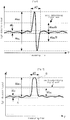
- FIGS. 7 and 8 are graphs illustrating examples of laser reflection signals detected on a weld by the on-line detection system according to an embodiment of the invention.
- the graph of FIG. 7 illustrates a waveform of a detection signal on a flash butt weld by the light detector
- FIG. 8 is on-line data produced in an actual cold rolling, which is a signal waveform acquired by increasing a circular spot as shown in (b) of FIG. 4 in the range from 1 mm to 30 mm.
- a signal indicating a weld is rarely discriminated from noises resulting from fine protrusions and indents on the surface of the steel strip.
- the light detector 11 itself outputs a too small value.
- the weld signal is most easily detected when the spot diameter is in the range from 4 mm to 6 mm, and more preferably 5 mm.
- detection may be performed easily when the line spot has a width ranging from 2 mm to 5 mm and a length ranging from 30 mm to 50 mm.
- the optimum size of the circular spot and/or the optimum shape thereof as shown in FIG. 6 may be varied according to welding type.
- a weld can be easily detected on-line according to the invention from any welding types currently performed in the cold rolling of an iron and steel mill.
- the reflectivity when the laser beam reflects from the surface of the steel strip 1, the reflectivity has a significant difference between a reflectivity signal level A detected from an ordinary steel strip surface and a reflectivity signal level B detected from the weld.
- the two reflectivity signal levels are compared with each other to locate the weld.
- the reflectivity signal level at a specific point is a preset reference signal level or indicative waveform level ⁇ I WL or more, the specific point is determined as a weld.
- FIG. 9 is a flowchart illustrating an on-line detection method for a weld of a steel strip according to an embodiment of the invention.
- a laser beam for emission onto the surface of the moving steel strip 1 is generated in S900, and its cross section is adjusted in S902.
- the step S902 of adjusting the laser beam cross section may be selectively executed.
- the laser beam is focused with the focusing lens 112 in S904, and emitted onto the surface of the moving steel strip 1 in S906.
- the laser beam is emitted onto the surface of the steel strip 1 preferably at a right angle.
- the laser beam As the laser beam is emitted onto the surface of the steel strip 1, the laser beam is reflected from the surface.
- the reflecting laser beam is detected continuously in S908, and its reflectivity is extracted in S910.
- the reflectivity of the reflecting laser beam is an index indicating the intensity thereof.
- the reflectivity of the reflecting laser beam extracted continuously shows an intensity larger than a preset threshold value at a specific point or interval, this point or interval is determined as a weld in S912 and S914.
- the laser beam reflecting from the surface of the steel strip is continuously detected to locate the weld based on the difference between the reflectivity signal on the weld and that on the ordinary portions of the steel strip.
- step S912 when the reflectivity signal level is larger than the preset threshold level and the reflectivity signal width is within a predetermined range, a corresponding point would be determined as a weld. This is to discriminate the actual weld from a situation where noises owing to protrusions and indents give an instantaneous and sharp rise to the signal level.
- the one-line detection system and method for a weld of a steel strip may include at least two of the laser reflectivity measuring mechanism 110.
- a weld moving at a high speed can be easily detected on-line without using a through hole as in the prior art. Furthermore, since a through hole is not necessary, productivity of cold rolled products can be enhanced and problems such as marking and fracture can be essentially excluded.
Landscapes
- Immunology (AREA)
- Pathology (AREA)
- Life Sciences & Earth Sciences (AREA)
- Chemical & Material Sciences (AREA)
- Analytical Chemistry (AREA)
- Biochemistry (AREA)
- Health & Medical Sciences (AREA)
- General Health & Medical Sciences (AREA)
- Physics & Mathematics (AREA)
- General Physics & Mathematics (AREA)
- Engineering & Computer Science (AREA)
- Textile Engineering (AREA)
- Mechanical Engineering (AREA)
- Laser Beam Processing (AREA)
- Investigating Materials By The Use Of Optical Means Adapted For Particular Applications (AREA)
- Length Measuring Devices By Optical Means (AREA)
Description
- The present invention relates to an on-line detection system and method for a weld of a steel strip, in particular, which scans a laser beam onto a steel strip moving at a high speed, and based on the reflectivity of the laser beam returning from the steel strip, locates on-line a weld of the steel strip.
- Generally, in cold rolling in an iron and steel mill, unit coils are welded together into a steel strip at a starting step of the cold rolling so that continuous rolling can be carried out, and the steel strip is cut along welds into the unit coils, at a finishing step of the cold rolling, which are then transported to a following process or shipped as final products. Accordingly, in the cold rolling, it is inevitably required to locate such welds in order to automatically and precisely control essential process equipment and trim the steel strip along the welds into the unit coils at the output side.
-
FIG. 1 is a detection system for a weld of a steel strip using a through hole according to the prior art. - Referring to
FIG. 1 , the conventional detection system for a weld of a steel strip has alight projector 3 and alight detector 4 arranged above and under a movingsteel strip 1 that is being transported. Thelight projector 3 is arranged in a position where detection on aweld 2 is needed, and illuminates light downward onto thesteel strip 1. Thelight detector 4 arranged under thesteel strip 1 detects the light passing through ahole 5 perforated in thesteel strip 1, thereby detecting acorresponding weld 2. - Such a conventional detection system needs the
hole 5 perforated adjacent to theweld 2 in order to detect theweld 2. However, this also needs to temporarily stop a corresponding line to perforate thesteel strip 1, and thus productivity is lowered. In addition, excess metal formed around thehole 5 damages or scratches the surface of a feed roll or mill roll. Then, the scratched roll disadvantageously transfers a mark onto the surface of a following steel strip. Where thesteel strip 1 is very thin or high carbon steel, thehole 5 may fracture thesteel strip 1. - Furthermore, in the conventional weld detection system using a hole, the
light projector 3 installed above thesteel strip 1, which is being transported for process, uses a general light source. Such a light source has a short lifetime and thus needs periodic replacement. Since thelight detector 4 is installed below thesteel strip 1 to detect light passing through thehole 5, the detection system is difficult to install but easily soiled by dropping dust or foreign materials. -
DE 2910658 A1 discloses an on-line detection system for a weld of a steel strip comprising: reflectivity measuring means for emitting a light beam using an LED onto a moving steel strip and continuously measuring the reflectivity of the light beam returning from the surface of the steel strip; and signal processing means for detecting a weld of the steel strip based on change in the reflectivity measured on the weld. - The present invention has been made to solve the foregoing problems of the prior art which detects a weld using a through hole. Therefore, an object of certain embodiments of the present invention is to provide an on-line detection system and method for a weld of a steel strip, which can emit a laser beam onto the surface of a steel strip moving at a high speed and measure the reflectivity of the laser beam reflecting from the same, thereby detecting the weld of the steel strip easily on-line without having to form the through hole.
- According to an aspect of the invention for realizing any of the objects, there is provided an on-line detection system for a weld of a steel strip. An on-line detection system for a weld of a steel strip comprising: reflectivity measuring means for emitting a laser beam onto a moving steel strip and continuously measuring the reflectivity of the laser beam returning from the surface of the steel strip; and signal processing means for detecting a weld of the steel strip based on change in the reflectivity measured on the weld, characterised in that the signal processing means is arranged to adjust a weld-determining signal level and a weld-determining time interval according to welding type.
- According to an embodiment of the invention, it is preferable that the reflectivity measuring means is arranged to emit the laser beam continuously at an angle ranging from 80° to 100° with respect to the surface of the steel strip. More preferably, the reflectivity measuring means is arranged to emit the laser beam perpendicularly to the surface of the steel strip.
- According to an embodiment of the invention, the reflectivity measuring means includes a laser beam generator for generating the laser beam; a focusing lens for focusing the laser beam; a collecting lens for collecting the laser beam reflecting from the surface of the steel strip; and a light detector for outputting an electric signal corresponding to the reflectivity of the collected laser beam. Here, the reflectivity measuring means may further include a beam adjuster for adjusting the cross section of the laser beam generated by the laser beam generator, in which the beam-adjusting means are arranged between the laser beam generator and the focusing lens.
- According to an embodiment of the invention, the beam adjuster preferably is arranged to adjust the laser beam emitted onto the surface of the steel strip into a circular spot having a diameter of 4mm to 6mm or a line spot having a width of 2mm to 5mm and a length of 30mm to 50mm.
- According to an embodiment of the invention, the focusing lens may include a spherical lens or a cylindrical lens.
- According to an embodiment of the invention, the laser beam emitted onto the surface of the steel strip may have a shape selected from the group consisting of point, circle and line.
- According to an embodiment of the invention, the signal processing means determines a specific point on the surface of the steel strip as the weld if the reflectivity of the laser beam returning from the specific point is out of a preset threshold value.
- According to an aspect of the invention for realizing any of the objects, there is provided an on-line detection method for a weld of a steel strip, comprising steps of: (a) emitting a laser beam onto the surface of a steel strip which is being transported; (b) continuously detecting the laser beam reflecting from the surface; (c) measuring the reflectivity of the reflecting laser beam; and (d) locating the weld based on change in the reflectivity, characterised in that the step (c), further comprises adjusting a weld-determining signal level and a weld-determining time interval according to welding type.
- According to an embodiment of the invention, the step (a) generates the laser beam and focuses the laser beam to emit onto the steel strip being transported. Here, the step (a) may further comprise adjusting the cross section size of the laser beam generated.
- According to an embodiment of the invention, the step (a) emits the laser beam perpendicularly onto the surface of the steel strip.
- According to an embodiment of the invention, the step (d) determines a specific point on the surface of the steel strip as the weld if the reflectivity of the laser beam returning from the specific point is out of a preset threshold value.
- According to certain embodiments of the invention as set forth above, a weld moving at a high speed can be easily detected on-line without using a through hole as in the prior art.
- Furthermore, according to certain embodiments of the invention, since a through hole is not necessary, productivity of cold rolled products can be enhanced and problems such as marking and fracture can be essentially excluded.
- Moreover, according to certain embodiments of the invention, it is possible to detect a weld easily and precisely on-line by emitting a laser beam continuously onto a steel strip and locating the weld based on the reflectivity difference between the weld and an ordinary steel strip surface.
-
-
FIG. 1 is a configuration view illustrating a detection system for a weld of a steel strip using a through hole according to the prior art; -
FIG. 2 is a schematic configuration view illustrating an on-line detection system for a weld of a steel strip according to an embodiment of the invention; -
FIG. 3 is a detailed configuration view of the on-line detection system for a weld of a steel strip of the invention; -
FIG. 4 is a top view illustrating examples of laser beam spots focused onto the surface of a steel strip according to an embodiment of the invention; -
FIG. 5 is a sectional view illustrating a weld shape formed by a flash butt welding according an embodiment of the invention; -
FIG. 6 is a graph illustrating a weld detection signal by a laser reflection measuring mechanism according to an embodiment of the invention; -
FIGS. 7 and8 are graphs illustrating examples of laser reflection signals detected on a weld by the on-line detection system according to an embodiment of the invention; and -
FIG. 9 is a flowchart illustrating an on-line detection method for a weld of a steel strip according to an embodiment of the invention. - Hereinafter preferred embodiments of the invention will be described in detail with reference to the accompanying drawings.
-
FIG. 2 is a schematic configuration view illustrating an on-line detection system for a weld of a steel strip according to an embodiment of the invention. - Referring to
FIG. 2 , the on-line detection system 100 for a weld of a steel strip of this invention includes a laserreflectivity measuring mechanism 110 and asignal processing mechanism 120. While a single one of the laserreflectivity measuring mechanism 110 is shown in the drawing, this is merely an illustrative embodiment of the invention. In another embodiment of the invention, two or more of the laser reflectivity measuring mechanism may be provided according to the width of thesteel strip 1. - The laser reflectivity measuring mechanism continuously emits a laser beam onto a moving steel strip, which is being transported, and continuously measures the reflectivity of the laser beam returning from the surface of the steel strip. The reflectivity of the laser beam is preferably an index indicating the intensity of the laser beam reflecting from the surface of the moving
steel strip 1, and detected different according to the reflectivity or absorbance of a steel strip itself, properties of a steel strip, surface roughness, surface irregularity, surface shape and so on. - The
signal processing mechanism 120 synthetically analyzes the reflectivity of the laser beam measured by the laserreflectivity measuring mechanism 110 to locate theweld 2. The reflectivity (or intensity) of the laser beam reflecting from the surface of thesteel strip 1 has a certain value when reflected from theweld 2 that is different from that of the laser beam reflected from other portions of thesteel strip 1. Therefore, the reflectivity from other portions of thesteel strip 1 is compared with that from theweld 2 in order to determine whether or not theweld 2 has passed the position onto which the laser beam is emitted. In this fashion, thesignal processing mechanism 120 can detect theweld 2 of thesteel strip 1 correctly and precisely by using the change in the reflectivity of the reflecting laser beam measured on theweld 2 of the movingsteel strip 1. - Here, it is preferable that the laser
reflectivity measuring mechanism 110 continuously emits the laser beam onto the surface of thesteel strip 1 at an incident angle of 80° to 100°. - More preferably, the laser beam is emitted perpendicularly onto the surface of the
steel strip 1. As the incidence angle of the laser beam onto the steel strip is closer to the right angle, the angle of the reflecting laser beam is also closer to the right angle. Then, the reflecting laser beam can be collected more efficiently, and it is easier to measure the reflectivity. That is, the reflecting laser beam is collected more when the incidence angle is closer to the right angle and the reflection angle of the laser beam is smaller since the laser beam reflecting and scattering from the surface of thesteel strip 1 is collected to measure the reflectivity of the laser beam. Therefore, the reliability for the reflectivity measurement is higher when the laser beam is emitted substantially in the right angle. -
FIG. 3 is a detailed configuration view of the on-line detection system for a weld of a steel strip of the invention. - Referring to
FIG. 3 , the on-line detection system for a weld of a steel strip according to this embodiment of the invention is generally constructed of the laserreflectivity measuring mechanism 110 and thesignal processing mechanism 120. The laserreflectivity measuring mechanism 110 includes alaser beam generator 111, a focusing lens 113, a collectinglens 114 and alight detector 115. Alternatively, as shown in the drawing, thereflectivity measuring mechanism 110 may further include an aperture 112 for adjusting the sectional area of a laser beam. - The
laser beam generator 111 generates a laser beam to be emitted onto the surface of the movingsteel strip 1. Thelaser beam generator 111 generates the laser beam by emitting it for example through a semiconductor laser. Optionally, the aperture 112 may adjust the cross section of the laser beam. The aperture 112 may be located between thelaser beam generator 111 and the focusing lens 113 to continuously adjust the cross section of the laser beam generated by thelaser beam generator 111. - The focusing lens 113 focuses the laser beam whose cross section is adjusted by the aperture 112 so that the laser beam is emitted onto the surface of the moving
steel strip 1. The focusing lens 113 may be a spherical lens or a cylindrical lens. Here, the shape of the laser beam emitted onto the steel strip may be varied according to the type of the focusing lens 113. - The collecting
lens 114 collects the laser beam reflecting from the surface of thesteel strip 1. The collectinglens 114 sends the laser beam reflecting from the surface of thesteel strip 1 to thelight detector 115. - The
light detector 115, upon receiving the reflecting laser beam collected by the collectinglens 114, converts the laser beam into an electric signal corresponding to the reflectivity of the laser beam. That is, thelight detector 115 preferably outputs an electric signal corresponding to the intensity of the reflecting laser beam. Thelight detector 115 may be a single detector or an array of detectors. - The electric signal corresponding to the reflectivity is sent from the
light detector 115 to thesignal processing mechanism 120, which detects theweld 2 of thesteel strip 1 based on the electric signal. For example, when the electric signal at a specific point of thesteel strip 1 is out of a preset critical value or change in the electrical signal at a specific point is out of a preset reference value, the specific point is determined as theweld 2. -
FIG. 4 is a top view illustrating examples of laser beam spots focused onto the surface of a steel strip according to an embodiment of the invention. - As illustrated in
FIG. 4 , laser beam spots emitted onto the surface of the movingsteel strip 1 may be variously shaped. Such a laser beam shape can be determined by the type of the focusing lens 113. For example, when the focusing lens 113 is spherical, the laser beam emitted onto thesteel strip 1 would form a point or circular spot as shown in (a) and (b) ofFIG. 4 . When the focusing lens 113 is cylindrical, the laser beam emitted onto thesteel strip 1 would form a horizontal or vertical line spot as shown in (c) and (d) ofFIG. 4 . While not shown in the drawing, as an alternative embodiment, the laser beam may be adapted to form a rectangle spot or a cross spot with two lines intersecting each other. - The size of each spot focused onto the surface of the
steel strip 1 may be changed according to the focal length f of the focusing lens 113. For example, when the focusing lens 113 is spherical, the spot diameter a increases with the focal length of the spherical lens increasing relatively more than the distance between the spherical lens and the steel strip. Furthermore, when the focal length of the spherical lens is fixed, the spot diameter a increases in proportion to the diameter of the laser beam passing through the aperture 112. According to this embodiment, the spot diameter a can be adjusted easily through the aperture 112 and the focal length of the spherical lens. - Likewise, when the focusing lens 113 is cylindrical, a line spot is emitted onto the surface of the
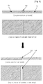
steel strip 1. In this case also, the spot length L1 or L2 can be adjusted easily through the aperture 112. The line spot length L1 or L2 is equal with the cross section size of the laser beam passing through the aperture 112. According to this embodiment, with the aperture 112 and the focusing lens 113, which is spherical or cylindrical, it is possible to form various spot shapes on the surface of thesteel strip 1 as shown inFIG. 4 . - In cold rolling in an iron and steel mill, several welding types are selectively performed according to the composition and thickness of steel strips, and welding shapes are varied according to such welding types. Where two coils are connected together via welding in the cold rolling, a strip or band-shaped weld is formed with a certain width as shown in
FIGS. 1 and 2 . This type of weld influences the performance of the light detector of thereflectivity measuring mechanism 110 with following factors: - (1) Laser beam reflectivity or absorbance of strip-shaped weld
- (2) Surface roughness of strip-shaped weld
- (3) Features of strip-shaped weld (roughness or bending)
- (4) Width of strip-shaped weld
- Of these factors, factors (1) to (3) decide the amplitude of output at the light detector, and factor (4) decides the time slot of an output signal. Change in laser reflectivity at the weld is decided by the weld shape, which is varied according to the welding type. The welding type carried out in the cold rolling of the iron and steel mill includes flash butt welding, laser welding, mesh seam welding and so on. Where steel strips are relatively thick, butt welding is carried out by flash butt welding or laser welding. In case of a thin steel strip such as a steel sheet, lap welding is carried out by mesh seam welding.
-
FIG. 5 is a sectional view illustrating a weld shape formed by a flash butt welding according an embodiment of the invention. In the cold rolling of the iron and steel mill, flash butt welding is carried out in Pickling line tandem Cold Mill (PCM). Such a welding leaves awelding bead 53, which damages feed and mill rolls. To prevent it, trimming 54 is performed. A trimmed portion 55 reveals inner steel strip material, which has a very high glossiness (reflectivity to laser beam). Therefore, the weld forms a high glossy strip 55 with a width of a few tens of mm in the width direction of the steel strip. On the other hand, laser welding leaves a welding bead with a narrow width (e.g., 1 mm to 2 mm) and a small height. Since trimming is not carried out, the welding bead is followed by a crease or groove, thereby forming an irregular surface structure. The irregular surface structure of the welding bead mainly changes the reflecting angle of a laser beam to vary the output of the light detector of the laserreflectivity measuring mechanism 110. Mesh seam welding is applied to lap welding of thin steel strips, thereby forming a stepped weld. Steps of the weld correspond to the thickness of each steel strip and extend in the thickness direction of the steel strips. The steps in the mesh seam weld also change the reflecting angle of a laser beam, thereby varying the output of the light detector of the laserreflectivity measuring mechanism 110. -
FIG. 6 is a graph illustrating a weld detection signal by a laser reflection measuring mechanism according to an embodiment of the invention. - As described above, the output of the light detector of the laser
reflectivity measuring mechanism 10 may be varied by different factors according to welding type. Accordingly, change in laser beam reflectivity at a weld as shown inFIG. 6 will be different also. To overcome such a problem of change in laser reflectivity according to welding type, the level of a reference signal for determining a weld (hereinafter will be shortly referred to as "weld-determining signal level") and the time interval of a signal for determining a weld (hereinafter will be shortly referred to as "weld-determining time interval" or "time interval") ΔT can be adjusted. That is, when the weld-determining signal level and weld-determining time interval ΔT are set according to welding type, on-line welding detection can be ensured stably regardless of welding type. - Referring to
FIG. 6 again, in case of attempting to detect a weld on the basis of change in the reflectivity of the reflecting laser beam measured by the light detector, the weld can be detected more stably when the difference between the output of the light detector measured on an ordinary steel strip surface and that measured on the weld is greater and a detection signal of the light detector on the weld has a larger time interval. InFIG. 6 , the reference sign ΔIN indicates a reflectivity deviation measured on the surface of thesteel strip 1, which originates from the vibration of the movingsteel strip 1 or noises related with surface defects. When the weld passes through a detection point, change in the output of the light detector has an amplitude of ΔIWH + ΔIWL with a time interval ΔT. To detect the weld stably inFIG. 6 , it is necessary to satisfy following condition.
- That is, it requires the amplitude of change in the output of the light detector ΔIWH +ΔIWL to be much larger than the reflectivity deviation ΔIN originating from strip vibration or surface detects. It is also required for the time interval ΔT of the change in the output of the light detector at the weld to be steady. When the time interval ΔT of the change in the output of the light detector is steady, it is possible to get rid of erroneous detection factors such as change in the output of the light detector owing to the surface defects of the steel strip. This is because that the time interval ΔT is not steady in general when the output of the light detector changes owing to the surface defects of the steel strip.
-
FIGS. 7 and8 are graphs illustrating examples of laser reflection signals detected on a weld by the on-line detection system according to an embodiment of the invention. - The graph of
FIG. 7 illustrates a waveform of a detection signal on a flash butt weld by the light detector, andFIG. 8 is on-line data produced in an actual cold rolling, which is a signal waveform acquired by increasing a circular spot as shown in (b) ofFIG. 4 in the range from 1 mm to 30 mm. According to this embodiment, when the circular spot of the laser beam has a too small diameter, a signal indicating a weld is rarely discriminated from noises resulting from fine protrusions and indents on the surface of the steel strip. On the other hand, when the circular spot is too large, the light detector 11 itself outputs a too small value. Therefore, it can be understood that the weld signal is most easily detected when the spot diameter is in the range from 4 mm to 6 mm, and more preferably 5 mm. According to another embodiment, although not shown in the drawings, when a laser beam emitted forms a line spot onto the surface of the steel strip, detection may be performed easily when the line spot has a width ranging from 2 mm to 5 mm and a length ranging from 30 mm to 50 mm. These data on the line spot are results obtained through a number of experiments, which show that a reflection laser beam is easily detectable at such width and length. - The optimum size of the circular spot and/or the optimum shape thereof as shown in
FIG. 6 may be varied according to welding type. Thus, when optimum spot size and shape are selected, a weld can be easily detected on-line according to the invention from any welding types currently performed in the cold rolling of an iron and steel mill. - In the graph of
FIG. 7 , when the laser beam reflects from the surface of thesteel strip 1, the reflectivity has a significant difference between a reflectivity signal level A detected from an ordinary steel strip surface and a reflectivity signal level B detected from the weld. The two reflectivity signal levels are compared with each other to locate the weld. In particular, when the reflectivity signal level at a specific point is a preset reference signal level or indicative waveform level ΔIWL or more, the specific point is determined as a weld. -
FIG. 9 is a flowchart illustrating an on-line detection method for a weld of a steel strip according to an embodiment of the invention. - Referring to
FIG. 9 , a laser beam for emission onto the surface of the movingsteel strip 1 is generated in S900, and its cross section is adjusted in S902. Here, the step S902 of adjusting the laser beam cross section may be selectively executed. The laser beam is focused with the focusing lens 112 in S904, and emitted onto the surface of the movingsteel strip 1 in S906. Here, the laser beam is emitted onto the surface of thesteel strip 1 preferably at a right angle. - As the laser beam is emitted onto the surface of the
steel strip 1, the laser beam is reflected from the surface. The reflecting laser beam is detected continuously in S908, and its reflectivity is extracted in S910. The reflectivity of the reflecting laser beam is an index indicating the intensity thereof. When the reflectivity of the reflecting laser beam extracted continuously shows an intensity larger than a preset threshold value at a specific point or interval, this point or interval is determined as a weld in S912 and S914. - In this process, the laser beam reflecting from the surface of the steel strip is continuously detected to locate the weld based on the difference between the reflectivity signal on the weld and that on the ordinary portions of the steel strip.
- In the step S912 above, when the reflectivity signal level is larger than the preset threshold level and the reflectivity signal width is within a predetermined range, a corresponding point would be determined as a weld. This is to discriminate the actual weld from a situation where noises owing to protrusions and indents give an instantaneous and sharp rise to the signal level.
- As described above, the one-line detection system and method for a weld of a steel strip may include at least two of the laser
reflectivity measuring mechanism 110. In this case, it is possible to detect a weld by using a detection signal from any one of the laserreflectivity measuring mechanism 110 or combining two or more detection signals. This is because to discriminate the weld or the strip 55, which is extended in a width direction of the steel strip, from high glossy surface defects which are formed locally. Since such localized high glossy surface defects do not have a uniform configuration, when the reflectivity is measured from two or more points in the width direction of the steel strip, it is highly unlikely that equal detection signals can be acquired from two or more defects. Accordingly, when morereflectivity measuring mechanisms 110 are installed in the width direction of the steel strip, erroneous detection resulting from surface effects will occur less. - According to certain embodiments of the invention as set forth above, a weld moving at a high speed can be easily detected on-line without using a through hole as in the prior art. Furthermore, since a through hole is not necessary, productivity of cold rolled products can be enhanced and problems such as marking and fracture can be essentially excluded.
- Moreover, according to certain embodiments of the invention, it is possible to detect a weld easily and precisely on-line by emitting a laser beam continuously onto a steel strip and locating the weld based on the reflectivity difference between the weld and an ordinary steel strip surface.
- It is to be understood that while the present invention has been illustrated and described in relation to certain embodiments in conjunction with the accompanying drawings, such embodiments and drawings are illustrative only and that the present invention is in no event to be limited thereto. Rather, it is contemplated that modifications and equivalents embodying the principles of the present invention will no doubt occur to those of skill in the art. It is therefore contemplated and intended that the invention shall be defined by the full scope of the claims appended hereto.
Claims (15)
- An on-line detection system (100) for a weld (2) of a steel strip (1) comprising:reflectivity measuring means (110) for emitting a laser beam onto a moving steel strip (1) and continuously measuring the reflectivity of the laser beam returning from the surface of the steel strip (1); andsignal processing means (120) for detecting a weld (2) of the steel strip based on change in the reflectivity measured on the weld (2),characterised in that the signal processing means (120) is arranged to adjust a weld-determining signal level and a weld-determining time interval (ΔT) according to welding type.
- The on-line detection system (100) of Claim 1, wherein the reflectivity measuring means (110) is arranged to emit the laser beam continuously at an angle ranging from 80° to 100° with respect to the surface of the steel strip (1).
- The on-line detection system (100) of Claim 2, wherein the reflectivity measuring means (110) is arranged to emit the laser beam perpendicularly to the surface of the steel strip (1).
- The on-line detection system (100) of Claim 1, wherein the reflectivity measuring means (110) includes:a laser beam generator (111) for generating the laser beam;a focusing lens (113) for focusing the laser beam;a collecting lens (114) for collecting the laser beam reflecting from the surface of the steel strip (1); anda light detector (115) for outputting an electric signal corresponding to the reflectivity of the collected laser beam.
- The on-line detection system (100) of Claim 4, wherein the reflectivity measuring means (110) further includes a beam adjuster (112) for adjusting the cross section of the laser beam generated by the laser beam generator (111).
- The on-line detection system (100) of Claim 5, wherein the beam adjuster (112) is arranged to adjust the laser beam emitted onto the surface of the steel strip into a circular spot having a diameter of 4mm to 6mm or a line spot having a width of 2mm to 5mm and a length of 30mm to 50mm.
- The on-line detection system (100) of Claim 4, wherein the focusing lens (113) comprises a spherical lens or a cylindrical lens.
- The on-line detection system (100) of Claim 4, wherein the laser beam emitted onto the surface of the steel strip (1) has a shape selected from the group consisting of point, circle and line.
- The on-line detection system (100) of Claim 1, wherein the signal processing means (120) determines a specific point on the surface of the steel strip (1) as the weld if the reflectivity of the laser beam returning from the specific point is out of a preset threshold value.
- An on-line detection method for a weld (2) of a steel strip (1), comprising steps of:(a) emitting a laser beam onto the surface of a steel strip (1) which is being transported;(b) continuously detecting the laser beam reflecting from the surface;(c) measuring the reflectivity of the reflecting laser beam; and(d) locating the weld (2) based on change in the reflectivity,characterised in that the step (c), further comprises adjusting a weld-determining signal level and a weld-determining time interval (ΔT) according to welding type.
- The on-line detection method of Claim 10, wherein the step (a) generates the laser beam and focuses the laser beam to emit onto the steel strip (1) being transported.
- The on-line detection method of Claim 11, wherein the step (a) further comprises adjusting the cross section size of the laser beam generated.
- The on-line detection method of Claim 10, wherein the step (a) emits the laser beam perpendicularly onto the surface of the steel strip (1).
- The on-line detection method of Claim 10, wherein the step (b) continuously detects the laser beam reflecting from at least two points arranged in the width direction of the steel strip (1).
- The on-line detection method of Claim 10, wherein the step (d) comprises determining a specific point on the surface of the steel strip (1) as the weld (2) if the reflectivity of the laser beam returning from the specific point is out of a preset threshold value.
Applications Claiming Priority (2)
| Application Number | Priority Date | Filing Date | Title |
|---|---|---|---|
| KR1020050129072A KR100797239B1 (en) | 2005-12-23 | 2005-12-23 | Online detection device and method for welded part of steel sheet |
| PCT/KR2006/002001 WO2007073023A1 (en) | 2005-12-23 | 2006-05-26 | Apparatus and method for on-line detecting welding part of strip |
Publications (3)
| Publication Number | Publication Date |
|---|---|
| EP1969346A1 EP1969346A1 (en) | 2008-09-17 |
| EP1969346A4 EP1969346A4 (en) | 2012-05-16 |
| EP1969346B1 true EP1969346B1 (en) | 2019-07-10 |
Family
ID=38188768
Family Applications (1)
| Application Number | Title | Priority Date | Filing Date |
|---|---|---|---|
| EP06768643.6A Active EP1969346B1 (en) | 2005-12-23 | 2006-05-26 | Apparatus and method for on-line detecting welding part of strip |
Country Status (6)
| Country | Link |
|---|---|
| US (1) | US8149409B2 (en) |
| EP (1) | EP1969346B1 (en) |
| JP (1) | JP2009520984A (en) |
| KR (1) | KR100797239B1 (en) |
| CN (1) | CN101416044B (en) |
| WO (1) | WO2007073023A1 (en) |
Families Citing this family (35)
| Publication number | Priority date | Publication date | Assignee | Title |
|---|---|---|---|---|
| KR101417042B1 (en) * | 2007-12-27 | 2014-07-08 | 주식회사 포스코 | Apparatus and method for detecting welding areas using laser beam |
| KR100957927B1 (en) * | 2008-04-10 | 2010-05-13 | 주식회사 포스코 | Strip tip detection device and strip winding device having same |
| JP5029676B2 (en) * | 2009-11-16 | 2012-09-19 | トヨタ自動車株式会社 | Weld detection method |
| CN102162795B (en) * | 2010-02-23 | 2013-03-13 | 宝山钢铁股份有限公司 | Method for comprehensive on-line detection of defects of band steel |
| US9121693B2 (en) * | 2010-09-03 | 2015-09-01 | Kabushiki Kaisha Bridgestone | Method and apparatus for detecting shape of strip-shaped member and two-dimensional displacement sensor |
| CN102608671A (en) * | 2011-10-27 | 2012-07-25 | 陶晶波 | Hot metal detecting probe |
| CN102680489B (en) * | 2012-04-05 | 2014-04-30 | 首钢总公司 | System for on-line detecting holes on surface of strip steel |
| CN102721366B (en) * | 2012-06-21 | 2015-01-07 | 张旭 | Method and device for tracking and measuring welding seam |
| CN103542819A (en) * | 2012-07-17 | 2014-01-29 | 宝山钢铁股份有限公司 | Detection and quality judgment method for strip steel weld surface appearance |
| WO2014098132A1 (en) * | 2012-12-18 | 2014-06-26 | 株式会社安川電機 | Seam welding apparatus, seam welding method, robot control device, and robot control method |
| CN103383326B (en) * | 2013-07-03 | 2015-05-27 | 首钢总公司 | On-line detection method and on-line detection mould of weld seam during continuous production of strip steel |
| CN103383360B (en) * | 2013-07-29 | 2016-01-13 | 重庆理工大学 | A kind of thin strap continuous casting blank surface defects sinusoidal grating phase shift detection device and detection method |
| DE102013112244B4 (en) * | 2013-08-06 | 2017-02-16 | Scansonic Mi Gmbh | Method for beam joining |
| CN103424411B (en) * | 2013-08-12 | 2016-04-20 | 昆明理工大学 | A kind of weld seam automatic checkout system |
| JP2015059773A (en) * | 2013-09-17 | 2015-03-30 | 高周波熱錬株式会社 | Heat treatment determination device, and heat treatment determination method |
| EP2963380B2 (en) * | 2014-07-04 | 2025-06-25 | Georg Fischer Rohrleitungssysteme AG | Contactless inspection for butt welding |
| JP6373714B2 (en) * | 2014-10-14 | 2018-08-15 | 株式会社アマダホールディングス | Direct diode laser processing apparatus and output monitoring method thereof |
| KR101647079B1 (en) * | 2014-12-04 | 2016-08-09 | 주식회사 포스코 | Apparatus and Method for preventing erroneous detection of welding part |
| CN104959876A (en) * | 2015-06-30 | 2015-10-07 | 开平太平洋绝缘材料有限公司 | Laser scanning device on automatic copper-clad plate shearing line |
| KR20170060471A (en) * | 2015-11-24 | 2017-06-01 | 주식회사 포스코 | Laser focusing device and method the same |
| CN106896138A (en) * | 2015-12-20 | 2017-06-27 | 南京诺威尔光电系统有限公司 | One kind scanning thermal excitation infrared imaging detecting system and method |
| CN105571502B (en) * | 2015-12-29 | 2019-08-09 | 上海交通大学 | Measurement Method of Weld Gap in Friction Stir Welding |
| CN106093074B (en) * | 2016-06-16 | 2020-01-07 | 广东工业大学 | A method for detecting solder joints of IC components based on robust principal component analysis |
| CN107234337B (en) * | 2017-06-27 | 2019-03-29 | 包头钢铁(集团)有限责任公司 | A kind of method of laser welder mild steel |
| CN107632017B (en) * | 2017-08-15 | 2023-08-15 | 广东省特种设备检测研究院珠海检测院 | A system and method for detecting joints of elevator T-shaped guide rails |
| JP2018151386A (en) * | 2018-03-09 | 2018-09-27 | 高周波熱錬株式会社 | Heat treatment determination device, and heat treatment determination method |
| JP6943812B2 (en) * | 2018-06-12 | 2021-10-06 | Ckd株式会社 | Inspection equipment, PTP packaging machine and PTP sheet manufacturing method |
| CN111122591B (en) * | 2020-01-07 | 2025-03-04 | 上海柏楚数控科技有限公司 | Detection and processing method, device and detection system for pipe welds |
| CN111429423B (en) * | 2020-03-19 | 2022-04-08 | 南通大学 | Multi-spectral welding image identification method based on quaternion multi-degree-of-freedom neurons |
| CN115220120A (en) * | 2021-04-14 | 2022-10-21 | 山西太钢不锈钢股份有限公司 | A device for online detection of the functions of steel strip patrolling and labeling and using method thereof |
| CN113503828B (en) * | 2021-06-17 | 2024-04-05 | 泰州隆基乐叶光伏科技有限公司 | Welding strip bending measuring device and measuring method |
| CN115980092B (en) * | 2023-03-20 | 2023-06-23 | 宁波吉宁汽车零部件有限公司 | Welding part detection equipment |
| CN117900973B (en) * | 2024-03-20 | 2024-05-24 | 太原市恒山机电设备有限公司 | Steel belt welding seam monitoring device and application method thereof |
| CN118650321B (en) * | 2024-07-31 | 2025-04-15 | 中电装备青岛豪迈钢结构有限公司 | An intelligent positioning system for welding points of iron towers |
| CN119368992B (en) * | 2024-11-07 | 2025-08-08 | 杭州联核科技有限公司 | Automatic welding device for forklift production |
Family Cites Families (33)
| Publication number | Priority date | Publication date | Assignee | Title |
|---|---|---|---|---|
| US4121087A (en) * | 1977-11-18 | 1978-10-17 | Rockwell International Corporation | Method and apparatus for controlling laser welding |
| JPS55106510A (en) | 1979-02-09 | 1980-08-15 | Hitachi Ltd | Magnetic packed tower |
| DE2910658A1 (en) * | 1979-03-17 | 1980-09-25 | Volkswagenwerk Ag | Automatic detection of plate material welding seams - by detecting simultaneous or staggered reflection decreases at two points |
| JPS56119670A (en) | 1980-02-22 | 1981-09-19 | Shin Meiwa Ind Co Ltd | Position detecting sensor of groove weld line |
| IL67986A0 (en) * | 1982-08-02 | 1983-06-15 | Gen Electric | Tri-axis seam tracker for electric arc torch position |
| JPS5928608A (en) | 1982-08-09 | 1984-02-15 | Matsushita Electric Ind Co Ltd | Detector for weld line |
| JPS59218213A (en) * | 1983-05-25 | 1984-12-08 | Nippon Steel Corp | Weld zone detecting method of band plate |
| JPS6056205A (en) | 1983-09-07 | 1985-04-01 | Mitsubishi Electric Corp | Welded part detector |
| US4578561A (en) * | 1984-08-16 | 1986-03-25 | General Electric Company | Method of enhancing weld pool boundary definition |
| US4734766A (en) * | 1985-08-19 | 1988-03-29 | Kawasaki Steel Corporation | Method and system for locating and inspecting seam weld in metal seam-welded pipe |
| JP2552695B2 (en) * | 1987-04-21 | 1996-11-13 | 株式会社リコー | Diolefin aromatic compound |
| US5150175A (en) * | 1991-03-13 | 1992-09-22 | American Research Corporation Of Virginia | Optical imaging system for fabric seam detection |
| US5245409A (en) * | 1991-11-27 | 1993-09-14 | Arvin Industries, Inc. | Tube seam weld inspection device |
| JPH0780645A (en) * | 1993-09-08 | 1995-03-28 | Fanuc Ltd | Cooling method of welding sensor |
| JPH07116849A (en) | 1993-10-26 | 1995-05-09 | Fanuc Ltd | Welding sensor provided with optical axis adjusting means |
| GB9323054D0 (en) * | 1993-11-09 | 1994-01-05 | British Nuclear Fuels Plc | Determination of the surface properties of an omject |
| JP2683874B2 (en) * | 1994-07-29 | 1997-12-03 | 長崎県 | Welding state detection method and device for laser welding |
| JPH08193811A (en) | 1995-01-12 | 1996-07-30 | Hitachi Zosen Corp | Weld detection device and weld detection method |
| JP3495212B2 (en) | 1995-12-25 | 2004-02-09 | カルソニックカンセイ株式会社 | Seam detection device for ERW pipe |
| DE59709824D1 (en) * | 1996-07-29 | 2003-05-22 | Elpatronic Ag Bergdietikon | Method and device for edge tracking and edge testing |
| PT836093E (en) * | 1996-10-10 | 2004-06-30 | Elpatronic Ag | PROCESS AND DEVICE FOR THE OPTICAL VERIFICATION OF WELDING SEAMS |
| JP3445722B2 (en) * | 1997-05-14 | 2003-09-08 | 出光石油化学株式会社 | Surface inspection device and surface inspection method |
| JP3247646B2 (en) * | 1997-10-24 | 2002-01-21 | 川崎製鉄株式会社 | Calibration method for surface inspection equipment |
| JP3560135B2 (en) * | 1999-03-23 | 2004-09-02 | 日産自動車株式会社 | Quality monitoring method for YAG laser welds |
| US6563575B1 (en) | 1999-08-10 | 2003-05-13 | Automated Technology Services, Inc. | Optical sensing system for detecting welds and defects in metal |
| FR2811427B1 (en) * | 2000-07-06 | 2002-10-25 | Aerospatiale Matra Ccr | METHOD FOR DETECTION AND IDENTIFICATION OF DEFECTS IN A WELDING CORD MADE BY LASER BEAM |
| EP1193490A1 (en) * | 2000-10-02 | 2002-04-03 | AEA Technology QSA GmbH | Method for weld seam testing and device therefore |
| JP2003139747A (en) | 2001-11-05 | 2003-05-14 | Kansai X Sen Kk | Method and device for ultrasonic flaw detection |
| PT1448334E (en) * | 2001-11-15 | 2011-06-28 | Precitec Vision Gmbh & Co Kg | Method and device for detecting the quality of a welding seam during the welding of workpieces |
| MY137246A (en) * | 2002-04-30 | 2009-01-30 | Jfe Steel Corp | Method and instrument for measuring bead cutting shape of electric welded tube |
| JP3823871B2 (en) * | 2002-04-30 | 2006-09-20 | Jfeスチール株式会社 | Method and apparatus for measuring bead cutting shape of ERW welded pipe |
| US6670574B1 (en) * | 2002-07-31 | 2003-12-30 | Unitek Miyachi Corporation | Laser weld monitor |
| DE20214969U1 (en) * | 2002-09-27 | 2004-02-19 | Rasselstein Hoesch Gmbh | Metal strip coil welded seam detection unit for deep drawn can manufacture uses detection of pulsed laser light scattering with threshold comparison |
-
2005
- 2005-12-23 KR KR1020050129072A patent/KR100797239B1/en not_active Expired - Lifetime
-
2006
- 2006-05-26 WO PCT/KR2006/002001 patent/WO2007073023A1/en not_active Ceased
- 2006-05-26 CN CN200680048140XA patent/CN101416044B/en active Active
- 2006-05-26 US US12/097,646 patent/US8149409B2/en active Active
- 2006-05-26 JP JP2008547082A patent/JP2009520984A/en active Pending
- 2006-05-26 EP EP06768643.6A patent/EP1969346B1/en active Active
Non-Patent Citations (1)
| Title |
|---|
| None * |
Also Published As
| Publication number | Publication date |
|---|---|
| EP1969346A1 (en) | 2008-09-17 |
| US20090279096A1 (en) | 2009-11-12 |
| CN101416044B (en) | 2012-07-04 |
| KR20070067810A (en) | 2007-06-29 |
| KR100797239B1 (en) | 2008-01-23 |
| US8149409B2 (en) | 2012-04-03 |
| CN101416044A (en) | 2009-04-22 |
| JP2009520984A (en) | 2009-05-28 |
| EP1969346A4 (en) | 2012-05-16 |
| WO2007073023A1 (en) | 2007-06-28 |
Similar Documents
| Publication | Publication Date | Title |
|---|---|---|
| US8149409B2 (en) | Apparatus and method for on-line detecting welding part of strip | |
| JP4531396B2 (en) | Method and apparatus for evaluating workpiece joints | |
| KR101361013B1 (en) | Method for the automatic analysis of a material bond | |
| JP5459922B2 (en) | Method and apparatus for measuring process parameters of a material processing process | |
| US8304691B2 (en) | Determining a focal position of a laser | |
| US20220161356A1 (en) | Laser processing system and jig | |
| US20120314225A1 (en) | Bead inspection method, and bead inspection apparatus | |
| WO2009006320A1 (en) | Sheet metal oxide detector | |
| JPH07110213A (en) | Joint measuring method | |
| CA2322531A1 (en) | Testing a weld seam | |
| JP3148658B2 (en) | Abnormal cause determination device for butt weld | |
| KR101428057B1 (en) | Apparatus and method for on-line detection of welds in steel plates | |
| KR20080058919A (en) | Online detection device and method for welded part of steel sheet | |
| Park et al. | Development of a weld quality monitoring system in CO 2 laser welding by using photodiodes | |
| JP3247646B2 (en) | Calibration method for surface inspection equipment | |
| JPH1177363A (en) | Method for inspecting fillet weld part, and device used therefor | |
| JP3064072B2 (en) | Method and apparatus for detecting weld shape during butt welding | |
| JPH07306161A (en) | Segregation detection method for metallic materials | |
| Ito et al. | Ultrasonic testing system for ERW mill | |
| JP2006038680A (en) | Strip shape detection method | |
| EP4032654B1 (en) | Laser processing device and processing state determination method | |
| JP2004257859A (en) | Edge shape detection method of metal band | |
| JPH0641034B2 (en) | Plasma automatic welding method | |
| JP4569967B2 (en) | Rolled material identification method and apparatus | |
| US6160235A (en) | Measurement of welds |
Legal Events
| Date | Code | Title | Description |
|---|---|---|---|
| PUAI | Public reference made under article 153(3) epc to a published international application that has entered the european phase |
Free format text: ORIGINAL CODE: 0009012 |
|
| 17P | Request for examination filed |
Effective date: 20080722 |
|
| AK | Designated contracting states |
Kind code of ref document: A1 Designated state(s): AT BE BG CH CY CZ DE DK EE ES FI FR GB GR HU IE IS IT LI LT LU LV MC NL PL PT RO SE SI SK TR |
|
| RIN1 | Information on inventor provided before grant (corrected) |
Inventor name: LIM, CHOONG-SOO Inventor name: OH, KI-JANG Inventor name: LEE, SANG-JIN Inventor name: SON, KI-SAM Inventor name: SON, KWANG-HO Inventor name: CHOI, SEUNG-GAP |
|
| A4 | Supplementary search report drawn up and despatched |
Effective date: 20120417 |
|
| RIC1 | Information provided on ipc code assigned before grant |
Ipc: G01N 21/55 20060101AFI20120411BHEP Ipc: G01N 21/89 20060101ALN20120411BHEP |
|
| DAX | Request for extension of the european patent (deleted) | ||
| 17Q | First examination report despatched |
Effective date: 20160122 |
|
| REG | Reference to a national code |
Ref country code: DE Ref legal event code: R079 Ref document number: 602006058295 Country of ref document: DE Free format text: PREVIOUS MAIN CLASS: G01N0021470000 Ipc: G01N0021550000 |
|
| RIC1 | Information provided on ipc code assigned before grant |
Ipc: G01N 21/55 20140101AFI20181120BHEP Ipc: G01N 21/89 20060101ALN20181120BHEP |
|
| GRAP | Despatch of communication of intention to grant a patent |
Free format text: ORIGINAL CODE: EPIDOSNIGR1 |
|
| STAA | Information on the status of an ep patent application or granted ep patent |
Free format text: STATUS: GRANT OF PATENT IS INTENDED |
|
| RIC1 | Information provided on ipc code assigned before grant |
Ipc: G01N 21/89 20060101ALN20181207BHEP Ipc: G01N 21/55 20140101AFI20181207BHEP |
|
| INTG | Intention to grant announced |
Effective date: 20190103 |
|
| GRAS | Grant fee paid |
Free format text: ORIGINAL CODE: EPIDOSNIGR3 |
|
| GRAA | (expected) grant |
Free format text: ORIGINAL CODE: 0009210 |
|
| STAA | Information on the status of an ep patent application or granted ep patent |
Free format text: STATUS: THE PATENT HAS BEEN GRANTED |
|
| AK | Designated contracting states |
Kind code of ref document: B1 Designated state(s): AT BE BG CH CY CZ DE DK EE ES FI FR GB GR HU IE IS IT LI LT LU LV MC NL PL PT RO SE SI SK TR |
|
| REG | Reference to a national code |
Ref country code: GB Ref legal event code: FG4D |
|
| REG | Reference to a national code |
Ref country code: CH Ref legal event code: EP Ref country code: AT Ref legal event code: REF Ref document number: 1154106 Country of ref document: AT Kind code of ref document: T Effective date: 20190715 |
|
| REG | Reference to a national code |
Ref country code: DE Ref legal event code: R096 Ref document number: 602006058295 Country of ref document: DE |
|
| REG | Reference to a national code |
Ref country code: IE Ref legal event code: FG4D |
|
| REG | Reference to a national code |
Ref country code: NL Ref legal event code: MP Effective date: 20190710 |
|
| REG | Reference to a national code |
Ref country code: LT Ref legal event code: MG4D |
|
| REG | Reference to a national code |
Ref country code: AT Ref legal event code: MK05 Ref document number: 1154106 Country of ref document: AT Kind code of ref document: T Effective date: 20190710 |
|
| PG25 | Lapsed in a contracting state [announced via postgrant information from national office to epo] |
Ref country code: LT Free format text: LAPSE BECAUSE OF FAILURE TO SUBMIT A TRANSLATION OF THE DESCRIPTION OR TO PAY THE FEE WITHIN THE PRESCRIBED TIME-LIMIT Effective date: 20190710 Ref country code: FI Free format text: LAPSE BECAUSE OF FAILURE TO SUBMIT A TRANSLATION OF THE DESCRIPTION OR TO PAY THE FEE WITHIN THE PRESCRIBED TIME-LIMIT Effective date: 20190710 Ref country code: PT Free format text: LAPSE BECAUSE OF FAILURE TO SUBMIT A TRANSLATION OF THE DESCRIPTION OR TO PAY THE FEE WITHIN THE PRESCRIBED TIME-LIMIT Effective date: 20191111 Ref country code: NL Free format text: LAPSE BECAUSE OF FAILURE TO SUBMIT A TRANSLATION OF THE DESCRIPTION OR TO PAY THE FEE WITHIN THE PRESCRIBED TIME-LIMIT Effective date: 20190710 Ref country code: BG Free format text: LAPSE BECAUSE OF FAILURE TO SUBMIT A TRANSLATION OF THE DESCRIPTION OR TO PAY THE FEE WITHIN THE PRESCRIBED TIME-LIMIT Effective date: 20191010 Ref country code: AT Free format text: LAPSE BECAUSE OF FAILURE TO SUBMIT A TRANSLATION OF THE DESCRIPTION OR TO PAY THE FEE WITHIN THE PRESCRIBED TIME-LIMIT Effective date: 20190710 Ref country code: SE Free format text: LAPSE BECAUSE OF FAILURE TO SUBMIT A TRANSLATION OF THE DESCRIPTION OR TO PAY THE FEE WITHIN THE PRESCRIBED TIME-LIMIT Effective date: 20190710 |
|
| PG25 | Lapsed in a contracting state [announced via postgrant information from national office to epo] |
Ref country code: IS Free format text: LAPSE BECAUSE OF FAILURE TO SUBMIT A TRANSLATION OF THE DESCRIPTION OR TO PAY THE FEE WITHIN THE PRESCRIBED TIME-LIMIT Effective date: 20191110 Ref country code: GR Free format text: LAPSE BECAUSE OF FAILURE TO SUBMIT A TRANSLATION OF THE DESCRIPTION OR TO PAY THE FEE WITHIN THE PRESCRIBED TIME-LIMIT Effective date: 20191011 Ref country code: LV Free format text: LAPSE BECAUSE OF FAILURE TO SUBMIT A TRANSLATION OF THE DESCRIPTION OR TO PAY THE FEE WITHIN THE PRESCRIBED TIME-LIMIT Effective date: 20190710 Ref country code: ES Free format text: LAPSE BECAUSE OF FAILURE TO SUBMIT A TRANSLATION OF THE DESCRIPTION OR TO PAY THE FEE WITHIN THE PRESCRIBED TIME-LIMIT Effective date: 20190710 |
|
| PG25 | Lapsed in a contracting state [announced via postgrant information from national office to epo] |
Ref country code: TR Free format text: LAPSE BECAUSE OF FAILURE TO SUBMIT A TRANSLATION OF THE DESCRIPTION OR TO PAY THE FEE WITHIN THE PRESCRIBED TIME-LIMIT Effective date: 20190710 |
|
| PG25 | Lapsed in a contracting state [announced via postgrant information from national office to epo] |
Ref country code: PL Free format text: LAPSE BECAUSE OF FAILURE TO SUBMIT A TRANSLATION OF THE DESCRIPTION OR TO PAY THE FEE WITHIN THE PRESCRIBED TIME-LIMIT Effective date: 20190710 Ref country code: EE Free format text: LAPSE BECAUSE OF FAILURE TO SUBMIT A TRANSLATION OF THE DESCRIPTION OR TO PAY THE FEE WITHIN THE PRESCRIBED TIME-LIMIT Effective date: 20190710 Ref country code: DK Free format text: LAPSE BECAUSE OF FAILURE TO SUBMIT A TRANSLATION OF THE DESCRIPTION OR TO PAY THE FEE WITHIN THE PRESCRIBED TIME-LIMIT Effective date: 20190710 Ref country code: IT Free format text: LAPSE BECAUSE OF FAILURE TO SUBMIT A TRANSLATION OF THE DESCRIPTION OR TO PAY THE FEE WITHIN THE PRESCRIBED TIME-LIMIT Effective date: 20190710 Ref country code: RO Free format text: LAPSE BECAUSE OF FAILURE TO SUBMIT A TRANSLATION OF THE DESCRIPTION OR TO PAY THE FEE WITHIN THE PRESCRIBED TIME-LIMIT Effective date: 20190710 |
|
| PG25 | Lapsed in a contracting state [announced via postgrant information from national office to epo] |
Ref country code: SK Free format text: LAPSE BECAUSE OF FAILURE TO SUBMIT A TRANSLATION OF THE DESCRIPTION OR TO PAY THE FEE WITHIN THE PRESCRIBED TIME-LIMIT Effective date: 20190710 Ref country code: CZ Free format text: LAPSE BECAUSE OF FAILURE TO SUBMIT A TRANSLATION OF THE DESCRIPTION OR TO PAY THE FEE WITHIN THE PRESCRIBED TIME-LIMIT Effective date: 20190710 Ref country code: IS Free format text: LAPSE BECAUSE OF FAILURE TO SUBMIT A TRANSLATION OF THE DESCRIPTION OR TO PAY THE FEE WITHIN THE PRESCRIBED TIME-LIMIT Effective date: 20200224 |
|
| REG | Reference to a national code |
Ref country code: DE Ref legal event code: R097 Ref document number: 602006058295 Country of ref document: DE |
|
| PLBE | No opposition filed within time limit |
Free format text: ORIGINAL CODE: 0009261 |
|
| STAA | Information on the status of an ep patent application or granted ep patent |
Free format text: STATUS: NO OPPOSITION FILED WITHIN TIME LIMIT |
|
| PG2D | Information on lapse in contracting state deleted |
Ref country code: IS |
|
| 26N | No opposition filed |
Effective date: 20200603 |
|
| PG25 | Lapsed in a contracting state [announced via postgrant information from national office to epo] |
Ref country code: SI Free format text: LAPSE BECAUSE OF FAILURE TO SUBMIT A TRANSLATION OF THE DESCRIPTION OR TO PAY THE FEE WITHIN THE PRESCRIBED TIME-LIMIT Effective date: 20190710 |
|
| PG25 | Lapsed in a contracting state [announced via postgrant information from national office to epo] |
Ref country code: LI Free format text: LAPSE BECAUSE OF NON-PAYMENT OF DUE FEES Effective date: 20200531 Ref country code: CH Free format text: LAPSE BECAUSE OF NON-PAYMENT OF DUE FEES Effective date: 20200531 Ref country code: MC Free format text: LAPSE BECAUSE OF FAILURE TO SUBMIT A TRANSLATION OF THE DESCRIPTION OR TO PAY THE FEE WITHIN THE PRESCRIBED TIME-LIMIT Effective date: 20190710 |
|
| REG | Reference to a national code |
Ref country code: BE Ref legal event code: MM Effective date: 20200531 |
|
| GBPC | Gb: european patent ceased through non-payment of renewal fee |
Effective date: 20200526 |
|
| PG25 | Lapsed in a contracting state [announced via postgrant information from national office to epo] |
Ref country code: LU Free format text: LAPSE BECAUSE OF NON-PAYMENT OF DUE FEES Effective date: 20200526 |
|
| PG25 | Lapsed in a contracting state [announced via postgrant information from national office to epo] |
Ref country code: GB Free format text: LAPSE BECAUSE OF NON-PAYMENT OF DUE FEES Effective date: 20200526 Ref country code: FR Free format text: LAPSE BECAUSE OF NON-PAYMENT OF DUE FEES Effective date: 20200531 Ref country code: IE Free format text: LAPSE BECAUSE OF NON-PAYMENT OF DUE FEES Effective date: 20200526 |
|
| PG25 | Lapsed in a contracting state [announced via postgrant information from national office to epo] |
Ref country code: BE Free format text: LAPSE BECAUSE OF NON-PAYMENT OF DUE FEES Effective date: 20200531 |
|
| PG25 | Lapsed in a contracting state [announced via postgrant information from national office to epo] |
Ref country code: CY Free format text: LAPSE BECAUSE OF FAILURE TO SUBMIT A TRANSLATION OF THE DESCRIPTION OR TO PAY THE FEE WITHIN THE PRESCRIBED TIME-LIMIT Effective date: 20190710 |
|
| REG | Reference to a national code |
Ref country code: DE Ref legal event code: R081 Ref document number: 602006058295 Country of ref document: DE Owner name: POSCO CO., LTD, POHANG-SI, KR Free format text: FORMER OWNER: POSCO, POHANG, KYUNGSANGBUK, KR Ref country code: DE Ref legal event code: R081 Ref document number: 602006058295 Country of ref document: DE Owner name: POSCO CO., LTD, POHANG- SI, KR Free format text: FORMER OWNER: POSCO, POHANG, KYUNGSANGBUK, KR Ref country code: DE Ref legal event code: R081 Ref document number: 602006058295 Country of ref document: DE Owner name: POSCO HOLDINGS INC., KR Free format text: FORMER OWNER: POSCO, POHANG, KYUNGSANGBUK, KR |
|
| REG | Reference to a national code |
Ref country code: DE Ref legal event code: R081 Ref document number: 602006058295 Country of ref document: DE Owner name: POSCO CO., LTD, POHANG-SI, KR Free format text: FORMER OWNER: POSCO HOLDINGS INC., SEOUL, KR Ref country code: DE Ref legal event code: R081 Ref document number: 602006058295 Country of ref document: DE Owner name: POSCO CO., LTD, POHANG- SI, KR Free format text: FORMER OWNER: POSCO HOLDINGS INC., SEOUL, KR |
|
| PGFP | Annual fee paid to national office [announced via postgrant information from national office to epo] |
Ref country code: DE Payment date: 20250520 Year of fee payment: 20 |