EP1968361A2 - Befestigungsstruktur für eine integrierte Schaltung - Google Patents
Befestigungsstruktur für eine integrierte Schaltung Download PDFInfo
- Publication number
- EP1968361A2 EP1968361A2 EP08003821A EP08003821A EP1968361A2 EP 1968361 A2 EP1968361 A2 EP 1968361A2 EP 08003821 A EP08003821 A EP 08003821A EP 08003821 A EP08003821 A EP 08003821A EP 1968361 A2 EP1968361 A2 EP 1968361A2
- Authority
- EP
- European Patent Office
- Prior art keywords
- face
- heat dissipation
- dissipation plate
- locking case
- fixing
- Prior art date
- Legal status (The legal status is an assumption and is not a legal conclusion. Google has not performed a legal analysis and makes no representation as to the accuracy of the status listed.)
- Withdrawn
Links
Images


Classifications
-
- H—ELECTRICITY
- H10—SEMICONDUCTOR DEVICES; ELECTRIC SOLID-STATE DEVICES NOT OTHERWISE PROVIDED FOR
- H10W—GENERIC PACKAGES, INTERCONNECTIONS, CONNECTORS OR OTHER CONSTRUCTIONAL DETAILS OF DEVICES COVERED BY CLASS H10
- H10W40/00—Arrangements for thermal protection or thermal control
- H10W40/60—Securing means for detachable heating or cooling arrangements, e.g. clamps
- H10W40/611—Bolts or screws
-
- H—ELECTRICITY
- H10—SEMICONDUCTOR DEVICES; ELECTRIC SOLID-STATE DEVICES NOT OTHERWISE PROVIDED FOR
- H10W—GENERIC PACKAGES, INTERCONNECTIONS, CONNECTORS OR OTHER CONSTRUCTIONAL DETAILS OF DEVICES COVERED BY CLASS H10
- H10W40/00—Arrangements for thermal protection or thermal control
- H10W40/20—Arrangements for cooling
- H10W40/231—Arrangements for cooling characterised by their places of attachment or cooling paths
- H10W40/235—Arrangements for cooling characterised by their places of attachment or cooling paths attached to package parts
-
- H—ELECTRICITY
- H10—SEMICONDUCTOR DEVICES; ELECTRIC SOLID-STATE DEVICES NOT OTHERWISE PROVIDED FOR
- H10W—GENERIC PACKAGES, INTERCONNECTIONS, CONNECTORS OR OTHER CONSTRUCTIONAL DETAILS OF DEVICES COVERED BY CLASS H10
- H10W40/00—Arrangements for thermal protection or thermal control
- H10W40/60—Securing means for detachable heating or cooling arrangements, e.g. clamps
Definitions
- the present invention relates to an IC fixing structure for fixing an integrated circuit (IC) to a heat dissipation plate, and more particularly to such an IC fixing structure for fixing an IC having no fixing part.
- IC integrated circuit
- ICs integrated circuits
- some ICs are provided with fixing parts which are to be fixed to radiating plates, respectively.
- the fixing part includes a screw hole through which a screw is inserted, for example.
- other ICs are not provided with such fixing parts as described above for the purpose of cost reduction.
- the ICs without fixing parts cannot be brought into a direct face-to-face contact with a heat dissipation plate.
- JP-A-2000-352024 discloses a heat dissipation plate to which an IC with no fixing parts is fixed.
- the heat dissipation plate includes a pressing part which links to a part of the heat dissipation plate at a bent part.
- a semiconductor device (IC) is inserted between the pressing part and the heat dissipation plate, and the pressing part is fastened up using a screw, whereby the semiconductor device is fixed.
- JP-A-2001-352024 discloses a structure for mounting a semiconductor device on a heat dissipation plate although not being related to fixing an IC to a heat dissipation plate. More specifically, the heat dissipation plate is bent so as to have a generally C-shaped section. Both end faces of the heat dissipation plate are bent thereby to be formed into semiconductor device locking parts. A semiconductor device is held between the heat dissipation plate and the semiconductor device locking parts, thereby being fixed.
- the heat dissipation plate disclosed in JP-A-2000-352024 has the following problem. That is, the heat dissipation plate cannot position the semiconductor device reliably. Accordingly, when mounted on a substrate, the IC moves within the heat dissipation plate, which movement renders the mounting of the IC difficult.
- JP-A-2001-352024 has the following problem. That is, the heat dissipation plate needs to be processed. As a result, a semiconductor device cannot be mounted on a ready-made radiator plate such as a heat dissipation plate.
- an object of the present invention is to provide an IC fixing structure which can reliably position the IC when the IC with no fixing parts is fixed to a ready-made heat dissipation plate.
- the present invention provides an Integrated Circuit (IC) fixing structure fixing an IC with no fixing part on a heat dissipation plate using an IC fixing component, characterized in that the IC fixing component includes a locking case accommodating the IC in such a manner that a side of the IC which is out of a face-to-face contact with the heat dissipation plate is brought into a face-to-face contact with the locking case so as to be covered and a fixing part having a through hole through which a screw member is inserted, and after the IC has been accommodated in the locking case, the IC fixing component is screwed to the heat dissipation plate using the through hole so that the side of the IC out of face-to-face contact with the locking case is pressed by the lower edge of the locking case thereby to be brought into a face-to-face contact with the heat dissipation plate.
- IC fixing component includes a locking case accommodating the IC in such a manner that a side of the IC which is out of
- the IC fixing component is accommodated in the locking case while being brought into a face-to-face contact with the locking case so that a side of the IC fixing component which is out of a face-to-face contact with the heat dissipation plate is covered.
- the IC fixing component is then screwed to the heat dissipation plate using the screw member having passed through the through hole.
- the locking case is screwed to the heat dissipation plate after the IC has been accommodated in the locking case.
- the side of the IC which is out of a face-to-face contact with the locking case is brought into a face-to-face contact with the heat dissipation plate and thereafter, the IC is fixed. Consequently, even when having no fixing part, the IC can reliably be positioned and fixed to an existing heat dissipation plate.
- the heat dissipation plate has a rotation limiting hole
- the fixing part has a rotation stop protrusion which is inserted into the rotation limiting hole when screwed to the heat dissipation plate. Rotation of the IC fixing component is limited by the rotation stop protrusion. Consequently, the IC fixing component can easily be fixed to the heat dissipation plate.
- the locking case has a side opposed to the side of the IC which is out of the face-to-face contact with the heat dissipation plate, said side of the locking case having an inwardly inclined lower edge, and the IC is pressed by the lower edge of the side of the locking case.
- the IC accommodated in the locking case is pressed to the heat dissipation plate side by the lower edge of the locking case. Consequently, heat dissipation of the IC can be improved by a simple construction.
- the locking case has a side opposed to the side of the IC which is out of the face-to-face contact with the heat dissipation plate, said side of the locking case being bent so as to form a step inside, and the IC is pressed by the step.
- the IC accommodated in the locking case is brought into a face-to-face contact with the step thereby to be held. In this case, too, heat dissipation of the IC can be improved by a simple construction.
- the IC fixing component comprises a plurality of ICs arranged in parallel, and the locking case has a cut-and-raised piece which is formed on a side thereof opposed to the side of each IC out of the face-to-face contact with the heat dissipation plate, the cut-and-raised piece being provided for positioning the ICs. Even when a plurality of ICs are employed, the IC fixing structure can reliably position the ICs.
- the invention also provides an Integrated Circuit (IC) fixing structure fixing an IC with no fixing part on a heat dissipation plate using an IC fixing component, wherein the heat dissipation plate has a rotation limiting hole and a screw hole, the IC fixing component includes a locking case formed by bending a thin steel plate and accommodating the IC in such a manner that a side of the IC which is out of a face-to-face contact with the heat dissipation plate is brought into a face-to-face contact with the locking case so as to be covered and a fixing part extending from a side surface of the locking case and having a through hole through which a screw member is inserted and a rotation stop protrusion inserted into the rotation limiting hole, the locking case having a side in a face-to-face contact with the IC, said side of the locking case in face-to-face contact with the IC having a lower edge inclined inward, and after the IC has been accommodated in the locking case, the screw member inserted through
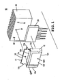
- an IC fixing structure is provided for fixing an IC 20 with no fixing through holes to a heat dissipation plate 30.
- the IC fixing structure 40 is constituted by an IC fixing component 10 and a simple processing applied to the heat dissipation plate 30.
- the IC fixing component 10 positions the IC 20 without use of a screw member. Furthermore, the IC fixing component 10 is screwed to the heat dissipation plate 30 after having positioned the IC 20. Since the IC fixing component reliably positions and brings the IC 20 into a face-to-face contact with the heat dissipation plate 30, the working efficiency can be improved in the case where the IC 20 is fixed to a substrate or the like. Furthermore, heat dissipation of the IC can be improved, and pieces of an IC broken can be prevented from scattering.
- the IC fixing component 10 is provided for positioning the IC 20 without use of a screw member as shown in FIGS. 1 and 2 .
- the IC fixing component 10 comprises a fixing part 11 and a locking case 12 connected to a lower end of the fixing part 11.
- the IC fixing component 10 is formed by bending a thin steel plate processed into a predetermined shape.
- the fixing part 11 includes a through hole 11a and rotation stop protrusions 11b.
- the through hole 11a is provided for fastening the IC fixing component 10 to the heat dissipation plate 30 with use of a screw member.
- the rotation stop protrusions 11b are inserted into rotation limiting holes 32 formed in the heat dissipation plate 30 respectively, thereby limiting rotation of the IC fixing component 10.
- the rotation stop protrusions 11b are formed by extending and inwardly bending both ends of the fixing part 11.
- the locking case 12 is provided for positioning and holding the IC 20.
- the locking case 12 includes an upper opposed face 12a, side opposed faces 12b and 12c, a rear opposed face 12d and an underside opposed face 12e in order to cover the IC 20 except for a side thereof brought into a face-to-face contact with the heat dissipation plate 30.
- the underside opposed face 12e is shaped so as be out of contact with terminals extending from the IC 20.
- the rear opposed face 12d is formed with a step 12d1 protruding inward.
- the step 12d1 is formed so as to protrude inward relative to the rear opposed face 12d, and the rear opposed face 12d has a lower edge inclined inward.
- the step 12d1 is formed by pressing or the like.
- the IC fixing component 10 which has positioned the IC 20 is screwed to the heat dissipation plate 30.
- the heat dissipation plate 30 has a screw hole 31 and rotation limiting holes 32 .
- the rotation stop protrusions 11b formed on the fixing part 11 of the IC fixing component 10 are inserted into the rotation limiting holes 32 respectively.
- the heat dissipation plate 30 is a heat sink which has the screw hole 31 and is further formed with the rotation limiting holes 32, for example.
- FIGS. 3A and 3B illustrate a manner of mounting an IC on a substrate using the IC fixing structure of the embodiment. Firstly, the IC 20 is accommodated in the locking case 12 of the fixing component 10 as shown in FIG. 3A . As a result, the IC 20 is locked by the upper opposed face 12a, side opposed faces 12b and 12c and underside opposed face 12e of the locking case 12 thereby to be fixed.
- the terminals can reliably be inserted into the respective holes of the substrate without movement of the IC 20 in the IC fixing component 10 even when the terminals of the IC 20 are inserted into the respective holes of the substrate with the heat dissipation plate 30 being held by a hand.
- heat dissipation of the IC 20 can be improved, and pieces of an IC broken can be prevented from scattering. More specifically, since the rear opposed face 12d of the IC fixing component 10 is formed with the step 12d1, the IC 20 is pressed to the heat dissipation plate 30 side so that the IC 20 is brought into a face-to-face contact with the heat dissipation plate 30. Consequently, heat dissipation of the IC 20 can further be improved. Furthermore, since the locking case 12 locking the IC 20 fixes the IC 20 so as to cover the IC 20 together with the heat dissipation plate 30. Consequently, even when the IC 20 is broken, pieces of the broken IC 20 can be prevented from scattering, whereupon the safety can be improved.
- the IC fixing structure 40 of the foregoing embodiment may be modified as follows.
- a plurality of ICs 20 may be fixed to the IC fixing component 10.
- the locking case 12 is formed so that the rear opposed face 12d has a length substantially equal to a width of the IC 20 to be accommodated.
- the rear opposed face 12d is formed with a cut-and-raised piece 13.
- three ICs 20 are juxtaposed, and six cut-and-raised pieces 13 are formed on both ends of the ICs 20. More specifically, generally C-shaped cu-and-raised pieces 13 are formed so as to be opposed to the sides of each IC 20 by bending.
- each IC 20 is brought into a face-to-face contact with the cut-and-raised pieces 13 respectively and are held between the upper and underside opposed faces 12a and 12e. Accordingly, both ends of each IC 20 are locked by the cut-and-raised pieces 13, thereby being reliably locked by the IC fixing component 10.
- the IC fixing structure 40 is provided for fixing the IC 20 with no fixing through hole to the heat dissipation plate 30.
- the IC fixing structure 40 is constituted by the IC fixing component 10 and the simple processing applied to the heat dissipation plate 30.
- the IC fixing component 10 positions the IC 20 without use of screws.
- the IC fixing component 10 which has positioned the IC 20 is fastened to the heat dissipation plate 30 by the screw. Since the IC fixing component 10 reliably positions the IC 20 and brings the IC 20 into a face-to-face contact with the heat dissipation plate 30, the IC fixing component 10 can improve the working efficiency in the case where the IC 20 is fixed to a substrate or the like.
Landscapes
- Cooling Or The Like Of Electrical Apparatus (AREA)
- Cooling Or The Like Of Semiconductors Or Solid State Devices (AREA)
Applications Claiming Priority (1)
| Application Number | Priority Date | Filing Date | Title |
|---|---|---|---|
| JP2007056383A JP2008218840A (ja) | 2007-03-06 | 2007-03-06 | Ic固定構造 |
Publications (2)
| Publication Number | Publication Date |
|---|---|
| EP1968361A2 true EP1968361A2 (de) | 2008-09-10 |
| EP1968361A3 EP1968361A3 (de) | 2010-07-07 |
Family
ID=39540772
Family Applications (1)
| Application Number | Title | Priority Date | Filing Date |
|---|---|---|---|
| EP08003821A Withdrawn EP1968361A3 (de) | 2007-03-06 | 2008-02-29 | Befestigungsstruktur für eine integrierte Schaltung |
Country Status (3)
| Country | Link |
|---|---|
| US (1) | US7663885B2 (de) |
| EP (1) | EP1968361A3 (de) |
| JP (1) | JP2008218840A (de) |
Families Citing this family (7)
| Publication number | Priority date | Publication date | Assignee | Title |
|---|---|---|---|---|
| JP5728865B2 (ja) * | 2010-01-07 | 2015-06-03 | 株式会社リコー | 放熱機構、及び放熱板の支え金具 |
| JP5779066B2 (ja) * | 2011-09-29 | 2015-09-16 | 新電元工業株式会社 | 電子部品ユニット |
| US20160057891A1 (en) * | 2013-05-03 | 2016-02-25 | Schneider Electric USA, Inc. | Heat sink and method of assemblying |
| US9646909B2 (en) * | 2014-12-30 | 2017-05-09 | Eaton Corporation | Electrical switch and mounting assembly therefor |
| US10123458B1 (en) | 2017-05-04 | 2018-11-06 | Eaton Intelligent Power Limited | Electrical switch and mounting assembly therefor |
| EP4307850B1 (de) * | 2019-11-18 | 2026-01-14 | Huawei Digital Power Technologies Co., Ltd. | Elektronisches bauteil mit gehäuserahmen, leiterplatte mit elektronischem bauteil und elektronische vorrichtung |
| TWI772243B (zh) * | 2022-01-12 | 2022-07-21 | 尼克森微電子股份有限公司 | 功率模組及功率裝置 |
Citations (2)
| Publication number | Priority date | Publication date | Assignee | Title |
|---|---|---|---|---|
| JP2000352024A (ja) | 1999-06-11 | 2000-12-19 | Sakai Heavy Ind Ltd | 舗装の目詰まり物の除去装置 |
| JP2001352024A (ja) | 2000-06-06 | 2001-12-21 | Nichicon Corp | 半導体の放熱板取付構造 |
Family Cites Families (15)
| Publication number | Priority date | Publication date | Assignee | Title |
|---|---|---|---|---|
| US3548927A (en) * | 1968-11-29 | 1970-12-22 | Intern Electronic Research Co | Heat dissipating retainer for electronic component |
| US3786317A (en) * | 1972-11-09 | 1974-01-15 | Bell Telephone Labor Inc | Microelectronic circuit package |
| US4729426A (en) * | 1986-03-06 | 1988-03-08 | Thermalloy Incorporated | Bonded clip heat sink |
| US5019942A (en) * | 1987-11-30 | 1991-05-28 | Thermalloy Incorporated | Insulating apparatus for electronic device assemblies |
| JPH0382063A (ja) * | 1989-08-24 | 1991-04-08 | Nec Corp | 半導体素子の放熱板への取付け方法 |
| US5450284A (en) * | 1994-02-17 | 1995-09-12 | Spacelabs Medical, Inc. | Heat sink and transistor retaining assembly |
| CN1152428C (zh) * | 1995-10-13 | 2004-06-02 | 热合金公司 | 可焊式晶体管夹子和夹子与散热器的组合装置 |
| CA2282644A1 (en) * | 1997-02-27 | 1998-09-03 | John Cennamo | Spring clip for attaching an electronic component to a heat sink and an assembly utilizing the same |
| JP2000323876A (ja) | 1999-05-10 | 2000-11-24 | Totoku Electric Co Ltd | 放熱板 |
| JP2003031987A (ja) * | 2001-07-12 | 2003-01-31 | Nec Yamagata Ltd | 電磁界遮蔽キャップ |
| US6587344B1 (en) * | 2002-02-13 | 2003-07-01 | Power-One, Inc. | Mounting system for high-voltage semiconductor device |
| JP3790225B2 (ja) * | 2003-03-25 | 2006-06-28 | 東芝キヤリア株式会社 | 放熱装置 |
| US7360586B2 (en) * | 2003-07-31 | 2008-04-22 | Fujitsu Limited | Wrap around heat sink apparatus and method |
| JP4154325B2 (ja) * | 2003-12-19 | 2008-09-24 | 株式会社日立産機システム | 電気回路モジュール |
| US20050264998A1 (en) * | 2004-05-25 | 2005-12-01 | 3M Innovative Properties Company | Heat sink assembly |
-
2007
- 2007-03-06 JP JP2007056383A patent/JP2008218840A/ja active Pending
-
2008
- 2008-02-29 US US12/074,158 patent/US7663885B2/en not_active Expired - Fee Related
- 2008-02-29 EP EP08003821A patent/EP1968361A3/de not_active Withdrawn
Patent Citations (2)
| Publication number | Priority date | Publication date | Assignee | Title |
|---|---|---|---|---|
| JP2000352024A (ja) | 1999-06-11 | 2000-12-19 | Sakai Heavy Ind Ltd | 舗装の目詰まり物の除去装置 |
| JP2001352024A (ja) | 2000-06-06 | 2001-12-21 | Nichicon Corp | 半導体の放熱板取付構造 |
Also Published As
| Publication number | Publication date |
|---|---|
| US7663885B2 (en) | 2010-02-16 |
| EP1968361A3 (de) | 2010-07-07 |
| US20080218978A1 (en) | 2008-09-11 |
| JP2008218840A (ja) | 2008-09-18 |
Similar Documents
| Publication | Publication Date | Title |
|---|---|---|
| EP1968361A2 (de) | Befestigungsstruktur für eine integrierte Schaltung | |
| US7457122B2 (en) | Memory module assembly including a clip for mounting a heat sink thereon | |
| US7349219B2 (en) | Memory module assembly including a clip for mounting a heat sink thereon | |
| US7723844B2 (en) | Heat dissipation device having a locking device | |
| US6822864B2 (en) | Heat-dissipating assembly and securing device used therein | |
| US7396247B2 (en) | Device for retaining a printed circuit board | |
| EP3050411B1 (de) | Fixierung eines kühlkörpers auf einem sfp/xfp-käfig | |
| US7430121B2 (en) | Heat sink fastener | |
| US7336496B1 (en) | Fixing structure for computer mainboard | |
| JP2016012578A (ja) | 放熱フィンの基板固定構造 | |
| US7190591B2 (en) | Heat sink assembly | |
| US8613595B2 (en) | Fan holder and heat dissipation device using the same | |
| CN101776942B (zh) | 散热器固定装置 | |
| KR101248416B1 (ko) | 클립형 방열장치 | |
| US8020609B2 (en) | Heat sink assembly having a clip | |
| US20090251863A1 (en) | Mounting device for mounting heat sink onto electronic component | |
| CN101336062A (zh) | 散热装置组合 | |
| JP3060218U (ja) | チップモジュールの放熱装置 | |
| JP3748733B2 (ja) | 電子機器の放熱装置 | |
| CN110837277A (zh) | 带有快速拆装硬盘框架的机箱 | |
| JP2012064885A (ja) | ヒートシンク取付構造 | |
| JP2005166907A (ja) | 立ち基板固定構造 | |
| KR200179726Y1 (ko) | 발열회로소자용 방열장치 | |
| KR101252046B1 (ko) | 반도체 모듈 및 방열판 | |
| TWI407886B (zh) | 電路板固定機構 |
Legal Events
| Date | Code | Title | Description |
|---|---|---|---|
| PUAI | Public reference made under article 153(3) epc to a published international application that has entered the european phase |
Free format text: ORIGINAL CODE: 0009012 |
|
| AK | Designated contracting states |
Kind code of ref document: A2 Designated state(s): AT BE BG CH CY CZ DE DK EE ES FI FR GB GR HR HU IE IS IT LI LT LU LV MC MT NL NO PL PT RO SE SI SK TR |
|
| AX | Request for extension of the european patent |
Extension state: AL BA MK RS |
|
| PUAL | Search report despatched |
Free format text: ORIGINAL CODE: 0009013 |
|
| AK | Designated contracting states |
Kind code of ref document: A3 Designated state(s): AT BE BG CH CY CZ DE DK EE ES FI FR GB GR HR HU IE IS IT LI LT LU LV MC MT NL NO PL PT RO SE SI SK TR |
|
| AX | Request for extension of the european patent |
Extension state: AL BA MK RS |
|
| AKY | No designation fees paid | ||
| STAA | Information on the status of an ep patent application or granted ep patent |
Free format text: STATUS: THE APPLICATION IS DEEMED TO BE WITHDRAWN |
|
| 18D | Application deemed to be withdrawn |
Effective date: 20110108 |