EP1966502B1 - Dispositif de synchronisation et bague de synchronisation pour dispositif de synchronisation - Google Patents
Dispositif de synchronisation et bague de synchronisation pour dispositif de synchronisation Download PDFInfo
- Publication number
- EP1966502B1 EP1966502B1 EP06829508A EP06829508A EP1966502B1 EP 1966502 B1 EP1966502 B1 EP 1966502B1 EP 06829508 A EP06829508 A EP 06829508A EP 06829508 A EP06829508 A EP 06829508A EP 1966502 B1 EP1966502 B1 EP 1966502B1
- Authority
- EP
- European Patent Office
- Prior art keywords
- synchronizer
- lug
- spring
- synchronizer ring
- stop
- Prior art date
- Legal status (The legal status is an assumption and is not a legal conclusion. Google has not performed a legal analysis and makes no representation as to the accuracy of the status listed.)
- Active
Links
- 239000011324 bead Substances 0.000 claims description 13
- 239000000463 material Substances 0.000 claims description 9
- 239000007769 metal material Substances 0.000 claims 2
- 230000005540 biological transmission Effects 0.000 abstract description 8
- 238000013508 migration Methods 0.000 abstract description 3
- 230000005012 migration Effects 0.000 abstract description 3
- 230000001360 synchronised effect Effects 0.000 description 13
- 238000000034 method Methods 0.000 description 4
- 230000002093 peripheral effect Effects 0.000 description 3
- 230000006835 compression Effects 0.000 description 2
- 238000007906 compression Methods 0.000 description 2
- 238000000465 moulding Methods 0.000 description 2
- 238000005192 partition Methods 0.000 description 2
- 240000001439 Opuntia Species 0.000 description 1
- 235000004727 Opuntia ficus indica Nutrition 0.000 description 1
- 238000011161 development Methods 0.000 description 1
- 230000018109 developmental process Effects 0.000 description 1
- 238000004080 punching Methods 0.000 description 1
Images

Classifications
-
- F—MECHANICAL ENGINEERING; LIGHTING; HEATING; WEAPONS; BLASTING
- F16—ENGINEERING ELEMENTS AND UNITS; GENERAL MEASURES FOR PRODUCING AND MAINTAINING EFFECTIVE FUNCTIONING OF MACHINES OR INSTALLATIONS; THERMAL INSULATION IN GENERAL
- F16D—COUPLINGS FOR TRANSMITTING ROTATION; CLUTCHES; BRAKES
- F16D23/00—Details of mechanically-actuated clutches not specific for one distinct type
- F16D23/02—Arrangements for synchronisation, also for power-operated clutches
- F16D23/025—Synchro rings
-
- F—MECHANICAL ENGINEERING; LIGHTING; HEATING; WEAPONS; BLASTING
- F16—ENGINEERING ELEMENTS AND UNITS; GENERAL MEASURES FOR PRODUCING AND MAINTAINING EFFECTIVE FUNCTIONING OF MACHINES OR INSTALLATIONS; THERMAL INSULATION IN GENERAL
- F16D—COUPLINGS FOR TRANSMITTING ROTATION; CLUTCHES; BRAKES
- F16D23/00—Details of mechanically-actuated clutches not specific for one distinct type
- F16D23/02—Arrangements for synchronisation, also for power-operated clutches
- F16D23/04—Arrangements for synchronisation, also for power-operated clutches with an additional friction clutch
- F16D23/06—Arrangements for synchronisation, also for power-operated clutches with an additional friction clutch and a blocking mechanism preventing the engagement of the main clutch prior to synchronisation
Definitions
- the invention relates to a synchronizer according to the preamble of claim 1 and a synchronizer ring according to the preamble of claim 10.
- a synchronizer body connected to a main shaft is used in currently used synchronizing devices for vehicle transmissions, which carries an axially displaceable sliding sleeve and the at least one side is assigned a synchronizer ring which is axially displaceable relative to the synchronizer body.
- plungers or synchronizing latch are mounted, which are pressed by a synchronizing spring against a sliding sleeve, which is carried by the synchronizer body.
- the synchronizing spring can be realized in different ways: In many cases, the synchronizing spring is a helical compression spring which presses a synchronizing bolt radially into the sliding sleeve.
- the synchronous spring as at least one annular spring, such as a wire spring, be formed, which is arranged on the inner peripheral side in the synchronizer body and thereby presses the synchronizer latch in the shift sleeve.
- the annular spring is displaceable in the axial direction on an inner circumferential wall of the synchronizer body and can .wandern in the axial direction.
- a generic synchronizer ring for a synchronizer is known.
- the synchronizer ring has a synchronizer ring stop; which is arranged between associated rotational stops of the synchronizer body.
- an axial stop is formed, which limits an axial migration of a spring element in the synchronizer body.
- Such synchronizer rings are also from the EP-A1-0 756 098 , of the U.S. Patent 4,776,228 and the EP-A1-0 816 704 known.
- a synchronizer ring for a synchronizer known, which is made of a sheet material in the stamping and drawing process.
- the driver or synchronous stops of the synchronizer ring are each formed as an axially extending, angled by the synchronizer ring tabs that can move between the associated rotational stops of the synchronizer ring and the shift sleeve.
- the object of the invention is to provide a synchronizer and a synchronizer ring, which allows a cost-effective and reliable mounting of the synchronizer ring spring in the synchronizer body.
- the object is achieved with the features of claim 1 or claim 10.
- Advantageous developments of the invention include the further claims.
- the invention as extending in the axial direction, angled from the synchronizer ring, preferably thin-walled lobes formed as an axial stop which limits the axial migration of the synchronous spring in the synchronizer body.
- the tab of the synchronizer ring can be brought into contact with the side stops with the rotational stops and, on the other hand, the tab can act as an axial stop for the synchronizing spring, preferably annular spring.
- the invention can be used for both a single and a multiple synchronization.
- the vehicle transmission can be designed as a manual transmission, a dual-clutch transmission or an automated transmission.
- the trained as a flap synchronizer ring stop or driver is formed with a mold portion in the form of a bead, which limits the synchronous spring in the axial direction.
- This makes it possible to form only the shape portion of the flap as a large-area axial stop, while the flap itself may have a low material thickness. It may already be sufficient if only the mold portion of the lobe of the synchronizing spring is axially opposite, while the lobe itself is provided in the radial direction outside of the synchronizing spring.
- the mold section also assists the lateral edges of the flap abutting against the rotational stops in their dimensional stability, so that the thin-walled flap is made more stable both in the axial direction and in the radial direction.
- the mold section may be formed at least in the end face in the flap, while the side edges - regardless of the mold section - are brought into contact with the rotational stops of the synchronizer body and the shift sleeve.
- the flap and / or its mold section can be spaced over a free space of a synchronizer cone of the synchronizer ring.
- the synchronizer cone is formed on an inner circumference of the synchronizer ring. Since in this case the flap or its form section are out of engagement with the synchronizing cone, the form section can be formed independently of the synchronizing cone in different shape variants.
- the molding section is designed as a bead formed in the flap in a stamping process that is particularly easy to produce.
- the bead may preferably extend centrally substantially parallel between the side edges of the flap.
- the synchronizer ring has substantially the same material thickness, at least with its tab and the mold section.
- a large-area axial stop of the flap is formed only by its molding section. An additional, complex compression of the flap to increase a stop surface for the system with the synchronous spring is therefore not necessary.
- the synchronizer ring according to the invention can be produced particularly easily and with reduced use of material from a sheet material in a stamping and / or drawing process.
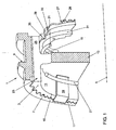
- a synchronizer 1 for a vehicle transmission is shown.
- a synchronizer body 3 of the synchronizer is fixedly connected to a main shaft, which in the Fig. 1 is indicated by dash-dotted lines with its axis 5.
- the synchronizer body 3 is provided on its outer circumference with a toothing 7 and carries over its toothing 7 an axially displaceable sliding sleeve. 9
- Fig. 1 is the synchronizer body 3 end formed with two opposite annular spaces 11, which are spaced from each other via a partition 13 in the axial direction.
- annular spaces 11 In the cylinder walls 15 of the annular spaces 11 continuous recesses 17 are formed in the axial direction, which interrupt the ring gear 7 of the synchronizer body 3.
- a synchronizing bolt 19 is arranged, which extends in the axial direction substantially over the entire length of the recess 17.
- the Indian Fig. 1 shown synchronizer bolt 19 is pressed over two, arranged in each case one of the annular spaces 11 Synchronfedem 21 against the shift sleeve 9.
- the Synchronfedem 21 are formed as Drahtringfedem.
- a groove 23 is shown with its one side wall 25.
- the side walls of the grooves 23 form rotational stops 25, one of which is shown in the sectional view.
- a synchronizing ring 27 is arranged with its synchronizing ring stop 29 or driver adjustable in a small angle of rotation.
- Fig. 1 is shown only on the right side of the synchronizer 3 of the synchronizer ring 27 and is omitted for reasons of clarity of the left side synchronizer ring 27.
- the shift sleeve 9 is axially displaced in the direction of a gear wheel, not shown, by means of a shift linkage, not shown, in a known manner in a single synchronization.
- the synchronizer latch 19 are taken from the shift sleeve 9.
- the synchronizer latch 19 press the synchronizer ring 27 with its synchronous taper 31 on a synchronizer cone of the gear, so that due to the resulting friction torque, the gear is taken in the direction of rotation and the synchronizer ring 27 abuts with its synchronizing ring stop 29 and driver against one of the rotational stops 25 and his ratchet teeth 28 blocks an axial movement of the shift sleeve 9.
- the synchronizer ring 27 used in the synchronizer 1 is shown.
- the synchronizer ring 27 is made of a sheet material of substantially the same material thickness in a drawing and punching process.
- the synchronizing ring stop 29 is formed as a flap extending in the axial direction, bent by the synchronizing ring 27.
- three equiangularly spaced lobes 29 are formed.
- the side edges 33 of the flap 29 form lateral abutment surfaces 34, which can be brought into contact respectively with associated rotational stops 25 of the synchronizer body 3.
- On its inner peripheral side of the synchronizer ring 27 is formed with its synchronous taper 31.
- the flap 29 has a centrally disposed between its side edges 33 centrally disposed bead 35, so that the flap 29 frontally enlarged by the bead 35, approximately V-shaped stop surface 36 for limiting the axial movement of the annular spring 21 is formed.
- the bead 35 of the flap 29 protrudes in accordance with the Fig. 1 radially into the annular spaces 11 of the synchronizer body 3 and with its tip of the wire ring spring 21 opposite.
- the Fig. 2 carries the synchronizer ring 27 at its periphery as external teeth, the sprocket teeth 28, which is interrupted by the three lobes 29.
- Each of the tabs 29 is spaced with its respective bead 35 over a free space a of the synchronous taper 31.
- a shape of the formed as a bead 35 forming portion can therefore be independent of the synchronous taper 31, as long as the tab 29 can be brought into contact with each of the synchronous body side torsion stops 25 and can act as an axial stop for the wire spring 21.
Landscapes
- Engineering & Computer Science (AREA)
- General Engineering & Computer Science (AREA)
- Mechanical Engineering (AREA)
- Mechanical Operated Clutches (AREA)
- Synchronisation In Digital Transmission Systems (AREA)
- Burglar Alarm Systems (AREA)
Claims (10)
- Dispositif de synchronisation pour une transmission de véhicule, comprenant au moins une bague de synchronisation (27) qui peut être déplacée axialement par rapport à un corps de synchronisation (3), et au moins un ressort de synchronisation (21) disposé du côté du corps de synchronisation, la bague de synchronisation (27) pouvant tourner avec une butée de bague de synchronisation (29) entre des butées de rotation associées (25) du corps de synchronisation (3) ou d'un manchon coulissant (9), et la butée de bague de synchronisation (29) étant réalisée sous forme de languette de préférence à paroi mince, s'étendant dans la direction axiale et coudée par rapport à la bague de synchronisation (27), la languette (29) étant réalisée sous forme d'une butée axiale, qui limite une migration axiale du ressort de synchronisation (21) dans le corps de synchronisation (3), caractérisé en ce que la bague de synchronisation (27) est fabriquée en un matériau en tôle dans lequel la butée axiale (35) est réalisée sous forme de moulure façonnée dans la languette (29).
- Dispositif de synchronisation selon la revendication 1, caractérisé en ce que la moulure (35) s'étend essentiellement parallèlement entre les arêtes latérales (33) de la languette (29) et/ou s'étend centralement.
- Dispositif de synchronisation selon l'une quelconque des revendications précédentes, caractérisé en ce que la languette (29) et/ou sa moulure (35) est/sont disposée(s) axialement en regard du ressort de synchronisation (21).
- Dispositif de synchronisation selon l'une quelconque des revendications précédentes, caractérise en ce que la languette (29) présente une surface de butée frontale (36) pour limiter la migration axiale du ressort de synchronisation (21) et/ou des surfaces de butée latérales (34) qui peuvent être amenées en appui contre les butées de rotation (25).
- Dispositif de synchronisation selon l'une quelconque des revendications précédentes, caractérisé en ce que la butée axiale (35) est réalisée au moins du côté frontal dans la languette (29).
- Dispositif de synchronisation selon l'une quelconque des revendications précédentes, caractérisé en ce que la languette (29) pénètre au moins avec sa butée axiale (35) dans un espace annulaire (11) du côté du corps de synchronisation, dans lequel est disposé le ressort de synchronisation (21) en forme de ressort annulaire.
- Dispositif de synchronisation selon l'une quelconque des revendications précédentes, caractérisé en ce que la butée axiale (35) de la languette (29) est espacée par le biais d'un espace intermédiaire libre (a) d'un cône de synchronisation (31) de la bague de synchronisation (27).
- Dispositif de synchronisation selon l'une quelconque des revendications précédentes, caractérisé en ce que la bague de synchronisation (27) conjointement avec sa languette (29) et/ou la butée axiale (35) présentent essentiellement la même épaisseur de matériau.
- Dispositif de synchronisation selon l'une quelconque des revendications précédentes, caractérisé en ce que l'élément de ressort (21) est réalisé sous la forme d'un ressort s'étendant sous forme annulaire' dans le corps de synchronisation (3), de préférence est réalisé en forme de ressort annulaire.
- Bague de synchronisation (27) pour un dispositif de synchronisation (1) d'une transmission de véhicule selon les revendications 1 à 9, comprenant une butée de bague de synchronisation (29) qui est réalisée sous forme de languette de préférence à paroi mince, coudée par rapport à la bague de synchronisation dans la direction axiale, la languette étant réalisée avec une butée axiale qui limite dans l'état monté de la bague de synchronisation une migration axiale d'un élément de ressort (21) dans le corps de synchronisation (3), caractérisée en ce que la bague de synchronisation (27) est fabriquée en un matériau en tôle dans lequel la butée axiale (35) est réalisée sous forme de moulure façonnée dans la languette (29).
Applications Claiming Priority (2)
| Application Number | Priority Date | Filing Date | Title |
|---|---|---|---|
| DE102005060572A DE102005060572A1 (de) | 2005-12-17 | 2005-12-17 | Synchronisiereinrichtung und Synchronring für eine Synchronisiereinrichtung |
| PCT/EP2006/011921 WO2007068432A1 (fr) | 2005-12-17 | 2006-12-12 | Dispositif de synchronisation et bague de synchronisation pour dispositif de synchronisation |
Publications (2)
| Publication Number | Publication Date |
|---|---|
| EP1966502A1 EP1966502A1 (fr) | 2008-09-10 |
| EP1966502B1 true EP1966502B1 (fr) | 2011-02-23 |
Family
ID=37907146
Family Applications (1)
| Application Number | Title | Priority Date | Filing Date |
|---|---|---|---|
| EP06829508A Active EP1966502B1 (fr) | 2005-12-17 | 2006-12-12 | Dispositif de synchronisation et bague de synchronisation pour dispositif de synchronisation |
Country Status (4)
| Country | Link |
|---|---|
| EP (1) | EP1966502B1 (fr) |
| AT (1) | ATE499538T1 (fr) |
| DE (2) | DE102005060572A1 (fr) |
| WO (1) | WO2007068432A1 (fr) |
Families Citing this family (6)
| Publication number | Priority date | Publication date | Assignee | Title |
|---|---|---|---|---|
| DE102008023031B4 (de) * | 2008-05-09 | 2011-01-05 | Diehl Metall Stiftung & Co. Kg | Blech-Synchronring |
| KR101558402B1 (ko) * | 2008-06-18 | 2015-10-07 | 오엘리콘 프릭션 시스템즈 (져머니) 게엠베하 | 차량용 동기 링 및 기어 변경 방식의 변속기 |
| EP2196281B1 (fr) * | 2008-12-11 | 2014-07-16 | Hoerbiger Antriebstechnik GmbH | Procédé de fabrication d'un anneau de synchronisation extérieur |
| DE102009041518A1 (de) * | 2009-09-14 | 2011-03-24 | Hoerbiger Antriebstechnik Gmbh | Schaltmuffe für ein Schaltgetriebe |
| DE102016206569B4 (de) | 2016-04-19 | 2018-04-26 | Schaeffler Technologies AG & Co. KG | Synchro-Ringfeder mit Arretierfunktion |
| KR102172569B1 (ko) * | 2018-12-11 | 2020-11-02 | 이티알 주식회사 | 응력이 강화된 러그를 구비한 변속기용 동기 링 및 이의 제작방법 |
Family Cites Families (10)
| Publication number | Priority date | Publication date | Assignee | Title |
|---|---|---|---|---|
| FR2250404A5 (en) * | 1973-10-31 | 1975-05-30 | Citroen Sa | Synchroniser for a gearbox - tension springs normally prevent contact between pinion and synchronising ring |
| FR2390633A1 (fr) * | 1977-05-09 | 1978-12-08 | Renault | Dispositif de synchronisation perfectionne |
| DE3519811C2 (de) * | 1985-06-03 | 1994-05-11 | Borg Warner Automotive Gmbh | Träger für einen Synchronisierring |
| US4776228A (en) * | 1986-07-07 | 1988-10-11 | Chrysler Motors Corporation | Strutless synchronizer |
| FR2733560B1 (fr) * | 1995-04-28 | 1997-06-13 | Renault | Dispositif de synchronisation pour boite de vitesses mecanique |
| US5620075B1 (en) * | 1995-07-28 | 1999-08-17 | Borg Warner Automotive | C-shaped synchronizer spring |
| FR2750183B1 (fr) * | 1996-06-20 | 1998-07-31 | Peugeot | Synchroniseur double pour l'accouplement alternatif de deux pignons a un arbre de boite de vitesses |
| FR2751712B1 (fr) * | 1996-07-24 | 1998-10-30 | Valeo | Bague de synchronisation pour un synchroniseur de boite de vitesses |
| DE19718905B4 (de) * | 1997-05-05 | 2005-08-25 | Ina-Schaeffler Kg | Synchronring mit angeschweißten Mitnehmernasen |
| DE10203019A1 (de) * | 2002-01-26 | 2003-08-14 | Ina Schaeffler Kg | Mehrteiliger Synchronring einer Synchronisiereinrichtung |
-
2005
- 2005-12-17 DE DE102005060572A patent/DE102005060572A1/de not_active Withdrawn
-
2006
- 2006-12-12 AT AT06829508T patent/ATE499538T1/de active
- 2006-12-12 WO PCT/EP2006/011921 patent/WO2007068432A1/fr active Application Filing
- 2006-12-12 EP EP06829508A patent/EP1966502B1/fr active Active
- 2006-12-12 DE DE502006008964T patent/DE502006008964D1/de active Active
Also Published As
| Publication number | Publication date |
|---|---|
| DE502006008964D1 (de) | 2011-04-07 |
| WO2007068432A1 (fr) | 2007-06-21 |
| DE102005060572A1 (de) | 2007-06-21 |
| EP1966502A1 (fr) | 2008-09-10 |
| ATE499538T1 (de) | 2011-03-15 |
Similar Documents
| Publication | Publication Date | Title |
|---|---|---|
| DE102008023031B4 (de) | Blech-Synchronring | |
| EP2478243B1 (fr) | Bague de transmission pour un ensemble de synchronisation de boîte de vitesses | |
| EP1966502B1 (fr) | Dispositif de synchronisation et bague de synchronisation pour dispositif de synchronisation | |
| EP0985857A2 (fr) | Manchon d'immobilisation d'un arbre de commande | |
| EP0710331A1 (fr) | Systeme de changement de vitesses a synchronisation a verrouillage | |
| DE102011103780A1 (de) | Synchronisationseinheit eines Schaltgetriebes | |
| DE102009027438A1 (de) | Synchronisierung für ein Schaltgetriebe | |
| EP0521843A1 (fr) | Anneau de friction | |
| DE102006053495A1 (de) | Schiebemuffe einer Synchronisiervorrichtung | |
| DE102011101557A1 (de) | Nachstelleinrichtung für eine Reibungskupplung | |
| EP1175569B1 (fr) | Element de synchronisation composite avec butee | |
| DE102012001836B4 (de) | Schalttransmitter eines sperrsynchronisierten Schaltgetriebes | |
| DE102016122729A1 (de) | Synchroneinheit für ein Schaltgetriebe | |
| DE102014114276A1 (de) | Scheibenbremse | |
| DE102008049978A1 (de) | Schalteinheit mit Kupplungskörper | |
| DE102015121705A1 (de) | Kupplungsanordnung, insbesondere zum optionalen Verbinden eines Luftverdichters mit einer Antriebseinrichtung | |
| DE202006010407U1 (de) | Schiebemuffe | |
| DE102007030507A1 (de) | Schiebemuffe | |
| EP1208313B1 (fr) | Corps de synchroniseur forme d'une piece moulee en tole | |
| EP2478244B1 (fr) | Manchon d'actionnement pour boîte de vitesses mécanique | |
| WO2013149774A1 (fr) | Ensemble moyeu de roue et joint rotatif | |
| EP1239175B1 (fr) | Embrayage avec un dispositif de synchronisation | |
| DE10018092B4 (de) | Synchronisiereinheit für Schaltkupplungen | |
| DE60011320T2 (de) | Synchronisiereinrichtung für ein Fahrzeuggetriebe | |
| DE4319135C2 (de) | Zahnräderwechselgetriebe für Kraftfahrzeuge |
Legal Events
| Date | Code | Title | Description |
|---|---|---|---|
| PUAI | Public reference made under article 153(3) epc to a published international application that has entered the european phase |
Free format text: ORIGINAL CODE: 0009012 |
|
| 17P | Request for examination filed |
Effective date: 20080717 |
|
| AK | Designated contracting states |
Kind code of ref document: A1 Designated state(s): AT BE BG CH CY CZ DE DK EE ES FI FR GB GR HU IE IS IT LI LT LU LV MC NL PL PT RO SE SI SK TR |
|
| RIN1 | Information on inventor provided before grant (corrected) |
Inventor name: GARRETT, DAVID, L. Inventor name: ALBRECHT, MICHAEL Inventor name: STORMER, BORIS Inventor name: SPRECKELS, MARCUS |
|
| RAP1 | Party data changed (applicant data changed or rights of an application transferred) |
Owner name: VOLSKSWAGEN AKTIENGESELLSCHAFT Owner name: SULZER EUROFLAMM GERMANY GMBH |
|
| 17Q | First examination report despatched |
Effective date: 20090713 |
|
| GRAP | Despatch of communication of intention to grant a patent |
Free format text: ORIGINAL CODE: EPIDOSNIGR1 |
|
| GRAS | Grant fee paid |
Free format text: ORIGINAL CODE: EPIDOSNIGR3 |
|
| RAP1 | Party data changed (applicant data changed or rights of an application transferred) |
Owner name: SULZER FRICTION SYSTEMS (GERMANY) GMBH Owner name: VOLSKSWAGEN AKTIENGESELLSCHAFT |
|
| GRAA | (expected) grant |
Free format text: ORIGINAL CODE: 0009210 |
|
| AK | Designated contracting states |
Kind code of ref document: B1 Designated state(s): AT BE BG CH CY CZ DE DK EE ES FI FR GB GR HU IE IS IT LI LT LU LV MC NL PL PT RO SE SI SK TR |
|
| REG | Reference to a national code |
Ref country code: GB Ref legal event code: FG4D Free format text: NOT ENGLISH |
|
| REG | Reference to a national code |
Ref country code: CH Ref legal event code: EP |
|
| REG | Reference to a national code |
Ref country code: IE Ref legal event code: FG4D Free format text: LANGUAGE OF EP DOCUMENT: GERMAN |
|
| REF | Corresponds to: |
Ref document number: 502006008964 Country of ref document: DE Date of ref document: 20110407 Kind code of ref document: P |
|
| REG | Reference to a national code |
Ref country code: DE Ref legal event code: R096 Ref document number: 502006008964 Country of ref document: DE Effective date: 20110407 |
|
| REG | Reference to a national code |
Ref country code: NL Ref legal event code: VDEP Effective date: 20110223 |
|
| LTIE | Lt: invalidation of european patent or patent extension |
Effective date: 20110223 |
|
| PG25 | Lapsed in a contracting state [announced via postgrant information from national office to epo] |
Ref country code: ES Free format text: LAPSE BECAUSE OF FAILURE TO SUBMIT A TRANSLATION OF THE DESCRIPTION OR TO PAY THE FEE WITHIN THE PRESCRIBED TIME-LIMIT Effective date: 20110603 Ref country code: GR Free format text: LAPSE BECAUSE OF FAILURE TO SUBMIT A TRANSLATION OF THE DESCRIPTION OR TO PAY THE FEE WITHIN THE PRESCRIBED TIME-LIMIT Effective date: 20110524 Ref country code: SE Free format text: LAPSE BECAUSE OF FAILURE TO SUBMIT A TRANSLATION OF THE DESCRIPTION OR TO PAY THE FEE WITHIN THE PRESCRIBED TIME-LIMIT Effective date: 20110223 Ref country code: LT Free format text: LAPSE BECAUSE OF FAILURE TO SUBMIT A TRANSLATION OF THE DESCRIPTION OR TO PAY THE FEE WITHIN THE PRESCRIBED TIME-LIMIT Effective date: 20110223 Ref country code: PT Free format text: LAPSE BECAUSE OF FAILURE TO SUBMIT A TRANSLATION OF THE DESCRIPTION OR TO PAY THE FEE WITHIN THE PRESCRIBED TIME-LIMIT Effective date: 20110623 Ref country code: LV Free format text: LAPSE BECAUSE OF FAILURE TO SUBMIT A TRANSLATION OF THE DESCRIPTION OR TO PAY THE FEE WITHIN THE PRESCRIBED TIME-LIMIT Effective date: 20110223 |
|
| PG25 | Lapsed in a contracting state [announced via postgrant information from national office to epo] |
Ref country code: NL Free format text: LAPSE BECAUSE OF FAILURE TO SUBMIT A TRANSLATION OF THE DESCRIPTION OR TO PAY THE FEE WITHIN THE PRESCRIBED TIME-LIMIT Effective date: 20110223 Ref country code: CY Free format text: LAPSE BECAUSE OF FAILURE TO SUBMIT A TRANSLATION OF THE DESCRIPTION OR TO PAY THE FEE WITHIN THE PRESCRIBED TIME-LIMIT Effective date: 20110223 Ref country code: FI Free format text: LAPSE BECAUSE OF FAILURE TO SUBMIT A TRANSLATION OF THE DESCRIPTION OR TO PAY THE FEE WITHIN THE PRESCRIBED TIME-LIMIT Effective date: 20110223 Ref country code: SI Free format text: LAPSE BECAUSE OF FAILURE TO SUBMIT A TRANSLATION OF THE DESCRIPTION OR TO PAY THE FEE WITHIN THE PRESCRIBED TIME-LIMIT Effective date: 20110223 Ref country code: BG Free format text: LAPSE BECAUSE OF FAILURE TO SUBMIT A TRANSLATION OF THE DESCRIPTION OR TO PAY THE FEE WITHIN THE PRESCRIBED TIME-LIMIT Effective date: 20110523 |
|
| REG | Reference to a national code |
Ref country code: IE Ref legal event code: FD4D |
|
| PG25 | Lapsed in a contracting state [announced via postgrant information from national office to epo] |
Ref country code: DK Free format text: LAPSE BECAUSE OF FAILURE TO SUBMIT A TRANSLATION OF THE DESCRIPTION OR TO PAY THE FEE WITHIN THE PRESCRIBED TIME-LIMIT Effective date: 20110223 Ref country code: IE Free format text: LAPSE BECAUSE OF FAILURE TO SUBMIT A TRANSLATION OF THE DESCRIPTION OR TO PAY THE FEE WITHIN THE PRESCRIBED TIME-LIMIT Effective date: 20110223 Ref country code: EE Free format text: LAPSE BECAUSE OF FAILURE TO SUBMIT A TRANSLATION OF THE DESCRIPTION OR TO PAY THE FEE WITHIN THE PRESCRIBED TIME-LIMIT Effective date: 20110223 |
|
| PG25 | Lapsed in a contracting state [announced via postgrant information from national office to epo] |
Ref country code: RO Free format text: LAPSE BECAUSE OF FAILURE TO SUBMIT A TRANSLATION OF THE DESCRIPTION OR TO PAY THE FEE WITHIN THE PRESCRIBED TIME-LIMIT Effective date: 20110223 Ref country code: SK Free format text: LAPSE BECAUSE OF FAILURE TO SUBMIT A TRANSLATION OF THE DESCRIPTION OR TO PAY THE FEE WITHIN THE PRESCRIBED TIME-LIMIT Effective date: 20110223 Ref country code: CZ Free format text: LAPSE BECAUSE OF FAILURE TO SUBMIT A TRANSLATION OF THE DESCRIPTION OR TO PAY THE FEE WITHIN THE PRESCRIBED TIME-LIMIT Effective date: 20110223 |
|
| PLBE | No opposition filed within time limit |
Free format text: ORIGINAL CODE: 0009261 |
|
| STAA | Information on the status of an ep patent application or granted ep patent |
Free format text: STATUS: NO OPPOSITION FILED WITHIN TIME LIMIT |
|
| 26N | No opposition filed |
Effective date: 20111124 |
|
| PG25 | Lapsed in a contracting state [announced via postgrant information from national office to epo] |
Ref country code: PL Free format text: LAPSE BECAUSE OF FAILURE TO SUBMIT A TRANSLATION OF THE DESCRIPTION OR TO PAY THE FEE WITHIN THE PRESCRIBED TIME-LIMIT Effective date: 20110223 |
|
| REG | Reference to a national code |
Ref country code: DE Ref legal event code: R097 Ref document number: 502006008964 Country of ref document: DE Effective date: 20111124 |
|
| PG25 | Lapsed in a contracting state [announced via postgrant information from national office to epo] |
Ref country code: IT Free format text: LAPSE BECAUSE OF FAILURE TO SUBMIT A TRANSLATION OF THE DESCRIPTION OR TO PAY THE FEE WITHIN THE PRESCRIBED TIME-LIMIT Effective date: 20110223 |
|
| BERE | Be: lapsed |
Owner name: SULZER FRICTION SYSTEMS (GERMANY) G.M.B.H. Effective date: 20111231 Owner name: VOLSKSWAGEN A.G. Effective date: 20111231 |
|
| PG25 | Lapsed in a contracting state [announced via postgrant information from national office to epo] |
Ref country code: MC Free format text: LAPSE BECAUSE OF NON-PAYMENT OF DUE FEES Effective date: 20111231 |
|
| REG | Reference to a national code |
Ref country code: CH Ref legal event code: PL |
|
| GBPC | Gb: european patent ceased through non-payment of renewal fee |
Effective date: 20111212 |
|
| PG25 | Lapsed in a contracting state [announced via postgrant information from national office to epo] |
Ref country code: BE Free format text: LAPSE BECAUSE OF NON-PAYMENT OF DUE FEES Effective date: 20111231 Ref country code: CH Free format text: LAPSE BECAUSE OF NON-PAYMENT OF DUE FEES Effective date: 20111231 Ref country code: GB Free format text: LAPSE BECAUSE OF NON-PAYMENT OF DUE FEES Effective date: 20111212 Ref country code: LI Free format text: LAPSE BECAUSE OF NON-PAYMENT OF DUE FEES Effective date: 20111231 |
|
| REG | Reference to a national code |
Ref country code: AT Ref legal event code: MM01 Ref document number: 499538 Country of ref document: AT Kind code of ref document: T Effective date: 20111212 |
|
| PG25 | Lapsed in a contracting state [announced via postgrant information from national office to epo] |
Ref country code: LU Free format text: LAPSE BECAUSE OF NON-PAYMENT OF DUE FEES Effective date: 20111212 |
|
| PG25 | Lapsed in a contracting state [announced via postgrant information from national office to epo] |
Ref country code: AT Free format text: LAPSE BECAUSE OF NON-PAYMENT OF DUE FEES Effective date: 20111212 |
|
| PG25 | Lapsed in a contracting state [announced via postgrant information from national office to epo] |
Ref country code: IS Free format text: LAPSE BECAUSE OF FAILURE TO SUBMIT A TRANSLATION OF THE DESCRIPTION OR TO PAY THE FEE WITHIN THE PRESCRIBED TIME-LIMIT Effective date: 20110223 |
|
| PG25 | Lapsed in a contracting state [announced via postgrant information from national office to epo] |
Ref country code: TR Free format text: LAPSE BECAUSE OF FAILURE TO SUBMIT A TRANSLATION OF THE DESCRIPTION OR TO PAY THE FEE WITHIN THE PRESCRIBED TIME-LIMIT Effective date: 20110223 |
|
| PG25 | Lapsed in a contracting state [announced via postgrant information from national office to epo] |
Ref country code: HU Free format text: LAPSE BECAUSE OF FAILURE TO SUBMIT A TRANSLATION OF THE DESCRIPTION OR TO PAY THE FEE WITHIN THE PRESCRIBED TIME-LIMIT Effective date: 20110223 |
|
| REG | Reference to a national code |
Ref country code: FR Ref legal event code: PLFP Year of fee payment: 10 |
|
| REG | Reference to a national code |
Ref country code: FR Ref legal event code: PLFP Year of fee payment: 11 |
|
| REG | Reference to a national code |
Ref country code: FR Ref legal event code: PLFP Year of fee payment: 12 |
|
| P01 | Opt-out of the competence of the unified patent court (upc) registered |
Effective date: 20230526 |
|
| PGFP | Annual fee paid to national office [announced via postgrant information from national office to epo] |
Ref country code: FR Payment date: 20231226 Year of fee payment: 18 Ref country code: DE Payment date: 20231231 Year of fee payment: 18 |