EP1965002A2 - Tragstruktur für Platten zur Wandverkleidung - Google Patents
Tragstruktur für Platten zur Wandverkleidung Download PDFInfo
- Publication number
- EP1965002A2 EP1965002A2 EP20080002813 EP08002813A EP1965002A2 EP 1965002 A2 EP1965002 A2 EP 1965002A2 EP 20080002813 EP20080002813 EP 20080002813 EP 08002813 A EP08002813 A EP 08002813A EP 1965002 A2 EP1965002 A2 EP 1965002A2
- Authority
- EP
- European Patent Office
- Prior art keywords
- profile section
- anchorage
- supporting profile
- cladding
- support structure
- Prior art date
- Legal status (The legal status is an assumption and is not a legal conclusion. Google has not performed a legal analysis and makes no representation as to the accuracy of the status listed.)
- Withdrawn
Links
Images


Classifications
-
- E—FIXED CONSTRUCTIONS
- E04—BUILDING
- E04F—FINISHING WORK ON BUILDINGS, e.g. STAIRS, FLOORS
- E04F13/00—Coverings or linings, e.g. for walls or ceilings
- E04F13/07—Coverings or linings, e.g. for walls or ceilings composed of covering or lining elements; Sub-structures therefor; Fastening means therefor
- E04F13/08—Coverings or linings, e.g. for walls or ceilings composed of covering or lining elements; Sub-structures therefor; Fastening means therefor composed of a plurality of similar covering or lining elements
- E04F13/0801—Separate fastening elements
- E04F13/0803—Separate fastening elements with load-supporting elongated furring elements between wall and covering elements
- E04F13/081—Separate fastening elements with load-supporting elongated furring elements between wall and covering elements with additional fastening elements between furring elements and covering elements
Definitions
- the present invention relates to a support structure for cladding slabs for cladding a wall which is to be clad according to the preamble of claim 1.
- the present invention relates to a support structure for wall cladding, in particular for cladding for ventilated walls arranged to allow the circulation of air within the air gap which is formed by the cladding material and the actual wall structure which is to be covered.
- the support structure comprises a support framework and anchorage members intended to hook onto the framework, the framework being intended to be fixed to the wall which is to be clad, while the anchorage members are fixable to the cladding slabs.
- ventilated walls In the building sector, the use of cladding walls supported by a support structure, such as ventilated walls, is nowadays increasingly widespread, particularly in the production of newly constructed buildings, inasmuch as it makes it possible to clad wall structures of large dimensions in a rapid and durable manner.
- the advantages arising from the use of ventilated walls mainly lie in the capacity for protecting the underlying wall structure from adverse weather conditions, ensuring correct ventilation thereof, and permitting the maximum amount of freedom in the choice of cladding material to be used.
- a further requirement is that of allowing the maximum degree of freedom of finishing of the cladding wall, for example, allowing the positioning of the slabs in such a way that a joint line of predetermined width becomes visible between the slabs, optionally capable of being stuccoed and/or sealed so as to impart to the cladding wall the appearance of a wall associated with the wall structure by adhesive means or other similar techniques.
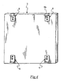
- the reference 1 indicates as a whole a support structure according to the invention for supporting a cladding structure 3 for cladding a wall W which is to be clad.
- the support structure 1 comprises a load-bearing framework 6 intended to be fixed to the wall W in order to support the cladding structure 3.
- the cladding structure 3 comprises a plurality of cladding slabs 2 arranged alongside one another to form a wall which is substantially continuous except for optional joint lines between the cladding slabs 2, as illustrated in Figures 1 and 5 .
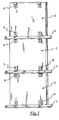
- the aforesaid load-bearing framework comprises a plurality of uprights 5 arranged parallel to and equidistant from one another and suitable for supporting a plurality of stringers 4.
- Each stringer 4 is in the form of a supporting profile section extending in a predetermined longitudinal direction X-X and comprises: a rear portion 4b suitable for permitting fixing to the wall W and a front portion 4a facing towards the cladding slabs 2 to be supported.
- the supporting profile section 4 is made of aluminium or another metallic material, for example a stainless steel, it being also possible to use materials of another type, for example a plastics material.
- the choice of material to be used for the production of the aforesaid supporting profile section should be made by taking into consideration the weight of the slabs of cladding material to be supported.
- the supporting profile section may be produced by extrusion ( Figures 6, 7 and 8 ) while in the case where a stainless steel is chosen, the supporting profile section may be produced by shearing and bending, starting from a sheet of suitable thickness ( Figure 9 ).
- the rear portion 4b of the supporting profile section 4 which forms the stringer is configured so as to form a flange 7 via which fixing to the uprights 5 can be carried out, for example by means of bolts, screws, welding and/or other forms of connection known per se.
- each stringer 4 may be fixed directly to the wall W which is to be clad by means of nogs, screws, rivets or other equivalent fixing means, so that the flange of the rear part of the stringer may be embedded or inserted into the wall W which is to be clad, during its production.
- the framework 6 will be formed only by the stringers 4.
- system for fixing the stringers 4 to the uprights 5 may provide for fixing means capable of permitting adjustment both in a vertical direction and for coming closer to/further away from the wall W which is to be clad.
- cladding slabs 2 may be elements such as flat slabs, tiles, small bricks, cladding panels or similar elements of any suitable material.
- the support structure 1 and the cladding slabs 2 supported by that support structure together form a complementary wall of cladding rigidly fixed to the wall W which is to be clad.
- the support structure 2 includes an upper anchorage member 8 and a lower anchorage member 11, which members, after being fixed to the back of a cladding slab 2, are suitable for being anchored to the profile sections 4 to effect the support of said cladding slabs on the framework 6.
- Figure 4 illustrates a cladding slab 2 to which the aforesaid upper 8 and lower 11 anchorage members have been fitted.
- the example shows an optimum situation which provides for the use of two upper anchorage members 8 fixed in proximity to the upper edge of the cladding slab 2 and of two corresponding lower anchorage members 11 fixed in proximity to the lower edge of the cladding slab 2, it being clear that, depending on the specific requirements, the number and positioning of the aforesaid anchorage members may be conveniently varied. Thus, for example, for particularly heavy cladding slabs it is possible to provide for a greater number of anchorage members.
- the manner in which the anchorage members 8 and 11 are fixed to the back of the cladding slabs 2 may be of any type, it being possible to provide for the use of adhesives and mastics, as well as expansion bolts or other equivalent systems.
- the anchorage members 8 and 11 may also be fitted to the cladding slabs in such a way as to engage the edge of the cladding slabs as well as suitable notches or seats previously provided in the cladding slabs.
- the anchorage members 8 and 11 are in the form of two profile sections conveniently obtained by shearing and bending, starting from a sheet of suitable thickness.
- Each supporting profile section 4 of the framework 6, when it is utilised in such a way as to take on the function of a stringer, as illustrated in Figure 2 , comprises a front portion 4a facing towards the cladding slabs 2 and which, with reference to its cross-section, forms a hollow profile accessible from the front of the supporting profile section 4 via an opening 14.
- this latter comprises:
- the aforesaid opening 14 is thus formed between the front portion L3 and the bottom portion L1 as can be clearly seen from Figures 6 to 9 .
- top portion L2 of the supporting profile section 4 is inclined at a predetermined angle A in such a way as to form an acute angle with the front portion L3 and, at the same time, to form with respect to the vertical a plane inclined away from the cladding slabs 2 supported.
- the front portion L3 of the supporting profile section 4 extends in a vertical plane and forms a vertical locating plane against which the back of the cladding slab rests.
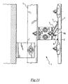
- an anchorage portion of the upper anchorage member 8 is inserted into said hollow profile of the supporting profile section via the opening 14, so as to effect the anchorage of the upper anchorage member 8 to the supporting profile section 4.
- the anchorage portion of the upper anchorage member 8 bears against the aforesaid bottom portion L1 of the supporting profile section 4 and interferes from inside with the front portion L3 of the supporting profile section 4, thus being retained inside the hollow profile of the supporting profile section 4.
- the aforesaid anchorage portion of the upper anchorage member 8 comprises a lower portion 8a configured so as to form an interlocking fit with the inner wall of the bottom portion L1 of the supporting profile section 4, and an upper portion 8b which is adapted to act against the inner wall of the front portion L3, abutting against it.
- the upper anchorage member 8 is a profile section and:
- an acute angle is formed between the profile section web 8b and the lower portion 8b of the upper anchorage member 8.
- the inner wall of the front portion L3 of the supporting profile section 4 comprises a set of teeth L3 oriented downwards, i.e. towards the bottom portion L1 of the supporting profile section 4, and suitable for opposing the displacement of the profile section web 8b towards the top portion L2 of the supporting profile section 4.
- the profile section web 8b of the upper anchorage member 8 extends for a length greater than the dimension of the opening 14 of the supporting profile section measured in the cross-section of the supporting profile section itself.
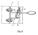
- a through hole 10 ( Figure 7, 8 , 11 , 12 , 13 and 14 ) to make it possible to act with a tool on the anchorage portion of the upper anchorage member at the front of the support structure.
- this has an anchorage portion 11 a which is adapted to bear from the outside on the hollow profile of the supporting profile section 4, so as to ensure convenient bearing anchorage of the lower anchorage member 11 on the supporting profile section 4.
- the aforesaid anchorage portion 11 a of the lower anchorage member 11 comes to bear from the outside on the top portion L2 of the supporting profile section 4.
- the lower anchorage member 11 is in the form of a profile section and the aforesaid anchorage portion 11a is in the form of an inclined web which extends towards the wall W which is to be clad.
- the inclined web 11a of the lower anchorage member 11 is inclined with respect to the vertical so as to form an acute angle and to diverge downwards with respect to the cladding slabs (2) supported by the framework 6.
- the inclination of the inclined web 11a coincides with the inclination of the top portion L2 of the supporting profile section 4.
- the free end of the inclined web 11 a of the lower anchorage member 11a is configured so as to engage in the manner of a hook a corresponding recess of the top portion L2 of the supporting profile section 4.
- the free end of the inclined web 11 a forms a hook 15 suitable for engaging a small tooth present in the outer wall of the top portion L2 of the supporting profile section 4.
- the free end of the inclined web 11 forms a hook 15 suitable for engaging the edge of a through hole 18 provided in the outer wall of the top portion L2 of the supporting profile section 4.
- Figures 10a, 10b and 10c illustrate the correct sequence for effecting the fixing of a cladding slab 2 to the framework 6.
- the insertion of the anchorage portion of the upper anchorage member 8 into the hollow profile of the supporting profile section 4 must necessarily take place while the slab in question is rotated with respect to the vertical as illustrated in Figure 10a .
- the dimension of the opening 14 of the hollow profile of the supporting profile section 4 is less than the length of the web of the profile section 8b.
- the cladding slab may be rotated as far as the vertical position illustrated in Figure 10b , having as a pivot for the rotation the supporting profile section 4 in which the anchorage portion of the upper anchorage member 8 is inserted.
- any further rotation of the cladding slab 2 towards the wall W which is to be clad is prevented by the fact that the rear portion of the cladding slab comes into abutment against the front portion L3 of the supporting profile section 4 shown lower down.
- the aforesaid rotation of the cladding slab 2 with respect to the supporting profile section 4 causes the profile section web 8b of the anchorage portion of the upper anchorage member 8 to interfere with the inner part of the front portion L3 of the supporting profile section 4.
- the interference established during the aforesaid rotation causes the anchorage portion of the upper anchorage member 8 to load itself like a spring and to act against the inner walls of the hollow profile section with a predetermined load, an indication of secure retention of the anchorage portion of the upper anchorage member in the supporting profile section 4.
- This descending movement has an advantageous effect, i.e. the inclined web 11a of the lower anchorage member 11 then interferes with the inclined top portion L2 of the supporting profile section 4, preventing the lower end of the cladding slab 2 from (detaching itself from?) the supporting profile section 4 shown lower down in Figure 10C .
- the support structure for slabs for cladding a wall which is to be clad makes it possible to satisfy the aforesaid requirements and at the same time remedy the drawbacks mentioned in the introduction of the description with reference to the prior art.
- the application of the cladding slabs 2 may be carried out in a simple, rapid and precise manner without the aid of any other external element, subject to the fixing of the anchorage members to the cladding slabs. This application is executed.
- Another advantage of the support structure and of the cladding structure according to the present invention lies in the fact that the anchorage members may be fixed to the cladding slabs in the workshop, so that on site it will be sufficient to arrange for the fixing of the framework to the wall to be clad and for the subsequent application of the cladding slabs.
Landscapes
- Engineering & Computer Science (AREA)
- Architecture (AREA)
- Civil Engineering (AREA)
- Structural Engineering (AREA)
- Finishing Walls (AREA)
- Joining Of Building Structures In Genera (AREA)
- Building Environments (AREA)
- Load-Bearing And Curtain Walls (AREA)
Applications Claiming Priority (1)
| Application Number | Priority Date | Filing Date | Title |
|---|---|---|---|
| ITMI20070395 ITMI20070395A1 (it) | 2007-02-28 | 2007-02-28 | Struttura di supporto per lastre di rivestimento di una parete da rivestire. |
Publications (1)
| Publication Number | Publication Date |
|---|---|
| EP1965002A2 true EP1965002A2 (de) | 2008-09-03 |
Family
ID=39486608
Family Applications (1)
| Application Number | Title | Priority Date | Filing Date |
|---|---|---|---|
| EP20080002813 Withdrawn EP1965002A2 (de) | 2007-02-28 | 2008-02-15 | Tragstruktur für Platten zur Wandverkleidung |
Country Status (4)
| Country | Link |
|---|---|
| EP (1) | EP1965002A2 (de) |
| CN (1) | CN101255762A (de) |
| EA (1) | EA200800445A1 (de) |
| IT (1) | ITMI20070395A1 (de) |
Families Citing this family (1)
| Publication number | Priority date | Publication date | Assignee | Title |
|---|---|---|---|---|
| CN102633179B (zh) * | 2012-04-27 | 2014-03-19 | 柏文元 | 一种用于电梯轿厢内装饰的插挂式装饰组件 |
-
2007
- 2007-02-28 IT ITMI20070395 patent/ITMI20070395A1/it unknown
-
2008
- 2008-02-15 EP EP20080002813 patent/EP1965002A2/de not_active Withdrawn
- 2008-02-27 EA EA200800445A patent/EA200800445A1/ru unknown
- 2008-02-28 CN CNA2008100820397A patent/CN101255762A/zh active Pending
Also Published As
| Publication number | Publication date |
|---|---|
| EA200800445A1 (ru) | 2008-08-29 |
| ITMI20070395A1 (it) | 2008-09-01 |
| CN101255762A (zh) | 2008-09-03 |
Similar Documents
| Publication | Publication Date | Title |
|---|---|---|
| US8365481B2 (en) | Anchorage system of ventilated facades | |
| US11255091B2 (en) | Support bracket apparatus | |
| KR100827716B1 (ko) | 고정 브라켓 | |
| US20060032157A1 (en) | Seismic wall system | |
| WO2010012061A1 (en) | Clip and support for installing cladding | |
| US20100242403A1 (en) | Multiple dimension beam, deck and column system | |
| CN114341445B (zh) | 外装板设置结构 | |
| US20100024347A1 (en) | Clamp | |
| EP1965002A2 (de) | Tragstruktur für Platten zur Wandverkleidung | |
| EP1918481A2 (de) | Belüftete Wand mit Stützelementen und Verkleidungsstruktur dafür | |
| EP3179008A1 (de) | Ziegelverkleidungssystem | |
| KR101275932B1 (ko) | 에이엘씨 패널을 종방향으로 콘크리트 슬래브에 설치하는 방법 | |
| CN213013896U (zh) | 一种桥梁施工用伸缩缝装置 | |
| RU2307906C2 (ru) | Способ монтажа вентилируемой облицовки зданий и конструкция ограждения для реализации способа | |
| RU2735006C1 (ru) | Устройство крепления крупноформатных навесных облицовочных панелей | |
| RU2735007C1 (ru) | Устройство для крепления крупноформатных навесных облицовочных панелей | |
| KR101940861B1 (ko) | 데크플레이트 및, 데크플레이트 시스템 | |
| EP3219869B1 (de) | Befestigungselement und wandelement eines gebäudes | |
| RU2616951C1 (ru) | Устройство скрытого крепления облицовочной панели в навесном вентилируемом фасаде | |
| US11248374B2 (en) | Facade support system | |
| JP2008008112A (ja) | 間仕切壁 | |
| CA3049211A1 (en) | Systems for recessing subfloor structures | |
| CN1973102A (zh) | 用于外壁绝热建筑物的壁外部结构和壁外部基部、用于壁外部材料安装的横向衬板框架以及采用横向衬板框架来覆盖壁的方法以及外部基部材料和采用外部基部材料的外壁 | |
| NL2029428B1 (en) | Brick slip wall cladding system | |
| KR20180131058A (ko) | 띄어 쌓기식 벽돌벽구조체 및 그 시공방법 |
Legal Events
| Date | Code | Title | Description |
|---|---|---|---|
| PUAI | Public reference made under article 153(3) epc to a published international application that has entered the european phase |
Free format text: ORIGINAL CODE: 0009012 |
|
| AK | Designated contracting states |
Kind code of ref document: A2 Designated state(s): AT BE BG CH CY CZ DE DK EE ES FI FR GB GR HR HU IE IS IT LI LT LU LV MC MT NL NO PL PT RO SE SI SK TR |
|
| AX | Request for extension of the european patent |
Extension state: AL BA MK RS |
|
| STAA | Information on the status of an ep patent application or granted ep patent |
Free format text: STATUS: THE APPLICATION IS DEEMED TO BE WITHDRAWN |
|
| 18D | Application deemed to be withdrawn |
Effective date: 20100831 |