EP1965002A2 - Support structure for slabs for cladding a wall to be clad - Google Patents
Support structure for slabs for cladding a wall to be clad Download PDFInfo
- Publication number
- EP1965002A2 EP1965002A2 EP20080002813 EP08002813A EP1965002A2 EP 1965002 A2 EP1965002 A2 EP 1965002A2 EP 20080002813 EP20080002813 EP 20080002813 EP 08002813 A EP08002813 A EP 08002813A EP 1965002 A2 EP1965002 A2 EP 1965002A2
- Authority
- EP
- European Patent Office
- Prior art keywords
- profile section
- anchorage
- supporting profile
- cladding
- support structure
- Prior art date
- Legal status (The legal status is an assumption and is not a legal conclusion. Google has not performed a legal analysis and makes no representation as to the accuracy of the status listed.)
- Withdrawn
Links
Images


Classifications
-
- E—FIXED CONSTRUCTIONS
- E04—BUILDING
- E04F—FINISHING WORK ON BUILDINGS, e.g. STAIRS, FLOORS
- E04F13/00—Coverings or linings, e.g. for walls or ceilings
- E04F13/07—Coverings or linings, e.g. for walls or ceilings composed of covering or lining elements; Sub-structures therefor; Fastening means therefor
- E04F13/08—Coverings or linings, e.g. for walls or ceilings composed of covering or lining elements; Sub-structures therefor; Fastening means therefor composed of a plurality of similar covering or lining elements
- E04F13/0801—Separate fastening elements
- E04F13/0803—Separate fastening elements with load-supporting elongated furring elements between wall and covering elements
- E04F13/081—Separate fastening elements with load-supporting elongated furring elements between wall and covering elements with additional fastening elements between furring elements and covering elements
Definitions
- the present invention relates to a support structure for cladding slabs for cladding a wall which is to be clad according to the preamble of claim 1.
- the present invention relates to a support structure for wall cladding, in particular for cladding for ventilated walls arranged to allow the circulation of air within the air gap which is formed by the cladding material and the actual wall structure which is to be covered.
- the support structure comprises a support framework and anchorage members intended to hook onto the framework, the framework being intended to be fixed to the wall which is to be clad, while the anchorage members are fixable to the cladding slabs.
- ventilated walls In the building sector, the use of cladding walls supported by a support structure, such as ventilated walls, is nowadays increasingly widespread, particularly in the production of newly constructed buildings, inasmuch as it makes it possible to clad wall structures of large dimensions in a rapid and durable manner.
- the advantages arising from the use of ventilated walls mainly lie in the capacity for protecting the underlying wall structure from adverse weather conditions, ensuring correct ventilation thereof, and permitting the maximum amount of freedom in the choice of cladding material to be used.
- a further requirement is that of allowing the maximum degree of freedom of finishing of the cladding wall, for example, allowing the positioning of the slabs in such a way that a joint line of predetermined width becomes visible between the slabs, optionally capable of being stuccoed and/or sealed so as to impart to the cladding wall the appearance of a wall associated with the wall structure by adhesive means or other similar techniques.
- the reference 1 indicates as a whole a support structure according to the invention for supporting a cladding structure 3 for cladding a wall W which is to be clad.
- the support structure 1 comprises a load-bearing framework 6 intended to be fixed to the wall W in order to support the cladding structure 3.
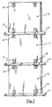
- the cladding structure 3 comprises a plurality of cladding slabs 2 arranged alongside one another to form a wall which is substantially continuous except for optional joint lines between the cladding slabs 2, as illustrated in Figures 1 and 5 .
- the aforesaid load-bearing framework comprises a plurality of uprights 5 arranged parallel to and equidistant from one another and suitable for supporting a plurality of stringers 4.
- Each stringer 4 is in the form of a supporting profile section extending in a predetermined longitudinal direction X-X and comprises: a rear portion 4b suitable for permitting fixing to the wall W and a front portion 4a facing towards the cladding slabs 2 to be supported.
- the supporting profile section 4 is made of aluminium or another metallic material, for example a stainless steel, it being also possible to use materials of another type, for example a plastics material.
- the choice of material to be used for the production of the aforesaid supporting profile section should be made by taking into consideration the weight of the slabs of cladding material to be supported.
- the supporting profile section may be produced by extrusion ( Figures 6, 7 and 8 ) while in the case where a stainless steel is chosen, the supporting profile section may be produced by shearing and bending, starting from a sheet of suitable thickness ( Figure 9 ).
- the rear portion 4b of the supporting profile section 4 which forms the stringer is configured so as to form a flange 7 via which fixing to the uprights 5 can be carried out, for example by means of bolts, screws, welding and/or other forms of connection known per se.
- each stringer 4 may be fixed directly to the wall W which is to be clad by means of nogs, screws, rivets or other equivalent fixing means, so that the flange of the rear part of the stringer may be embedded or inserted into the wall W which is to be clad, during its production.
- the framework 6 will be formed only by the stringers 4.
- system for fixing the stringers 4 to the uprights 5 may provide for fixing means capable of permitting adjustment both in a vertical direction and for coming closer to/further away from the wall W which is to be clad.
- cladding slabs 2 may be elements such as flat slabs, tiles, small bricks, cladding panels or similar elements of any suitable material.
- the support structure 1 and the cladding slabs 2 supported by that support structure together form a complementary wall of cladding rigidly fixed to the wall W which is to be clad.
- the support structure 2 includes an upper anchorage member 8 and a lower anchorage member 11, which members, after being fixed to the back of a cladding slab 2, are suitable for being anchored to the profile sections 4 to effect the support of said cladding slabs on the framework 6.
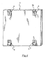
- Figure 4 illustrates a cladding slab 2 to which the aforesaid upper 8 and lower 11 anchorage members have been fitted.
- the example shows an optimum situation which provides for the use of two upper anchorage members 8 fixed in proximity to the upper edge of the cladding slab 2 and of two corresponding lower anchorage members 11 fixed in proximity to the lower edge of the cladding slab 2, it being clear that, depending on the specific requirements, the number and positioning of the aforesaid anchorage members may be conveniently varied. Thus, for example, for particularly heavy cladding slabs it is possible to provide for a greater number of anchorage members.
- the manner in which the anchorage members 8 and 11 are fixed to the back of the cladding slabs 2 may be of any type, it being possible to provide for the use of adhesives and mastics, as well as expansion bolts or other equivalent systems.
- the anchorage members 8 and 11 may also be fitted to the cladding slabs in such a way as to engage the edge of the cladding slabs as well as suitable notches or seats previously provided in the cladding slabs.
- the anchorage members 8 and 11 are in the form of two profile sections conveniently obtained by shearing and bending, starting from a sheet of suitable thickness.
- Each supporting profile section 4 of the framework 6, when it is utilised in such a way as to take on the function of a stringer, as illustrated in Figure 2 , comprises a front portion 4a facing towards the cladding slabs 2 and which, with reference to its cross-section, forms a hollow profile accessible from the front of the supporting profile section 4 via an opening 14.
- this latter comprises:
- the aforesaid opening 14 is thus formed between the front portion L3 and the bottom portion L1 as can be clearly seen from Figures 6 to 9 .
- top portion L2 of the supporting profile section 4 is inclined at a predetermined angle A in such a way as to form an acute angle with the front portion L3 and, at the same time, to form with respect to the vertical a plane inclined away from the cladding slabs 2 supported.
- the front portion L3 of the supporting profile section 4 extends in a vertical plane and forms a vertical locating plane against which the back of the cladding slab rests.
- an anchorage portion of the upper anchorage member 8 is inserted into said hollow profile of the supporting profile section via the opening 14, so as to effect the anchorage of the upper anchorage member 8 to the supporting profile section 4.
- the anchorage portion of the upper anchorage member 8 bears against the aforesaid bottom portion L1 of the supporting profile section 4 and interferes from inside with the front portion L3 of the supporting profile section 4, thus being retained inside the hollow profile of the supporting profile section 4.
- the aforesaid anchorage portion of the upper anchorage member 8 comprises a lower portion 8a configured so as to form an interlocking fit with the inner wall of the bottom portion L1 of the supporting profile section 4, and an upper portion 8b which is adapted to act against the inner wall of the front portion L3, abutting against it.
- the upper anchorage member 8 is a profile section and:
- an acute angle is formed between the profile section web 8b and the lower portion 8b of the upper anchorage member 8.
- the inner wall of the front portion L3 of the supporting profile section 4 comprises a set of teeth L3 oriented downwards, i.e. towards the bottom portion L1 of the supporting profile section 4, and suitable for opposing the displacement of the profile section web 8b towards the top portion L2 of the supporting profile section 4.
- the profile section web 8b of the upper anchorage member 8 extends for a length greater than the dimension of the opening 14 of the supporting profile section measured in the cross-section of the supporting profile section itself.
- a through hole 10 ( Figure 7, 8 , 11 , 12 , 13 and 14 ) to make it possible to act with a tool on the anchorage portion of the upper anchorage member at the front of the support structure.
- this has an anchorage portion 11 a which is adapted to bear from the outside on the hollow profile of the supporting profile section 4, so as to ensure convenient bearing anchorage of the lower anchorage member 11 on the supporting profile section 4.
- the aforesaid anchorage portion 11 a of the lower anchorage member 11 comes to bear from the outside on the top portion L2 of the supporting profile section 4.
- the lower anchorage member 11 is in the form of a profile section and the aforesaid anchorage portion 11a is in the form of an inclined web which extends towards the wall W which is to be clad.
- the inclined web 11a of the lower anchorage member 11 is inclined with respect to the vertical so as to form an acute angle and to diverge downwards with respect to the cladding slabs (2) supported by the framework 6.
- the inclination of the inclined web 11a coincides with the inclination of the top portion L2 of the supporting profile section 4.
- the free end of the inclined web 11 a of the lower anchorage member 11a is configured so as to engage in the manner of a hook a corresponding recess of the top portion L2 of the supporting profile section 4.
- the free end of the inclined web 11 a forms a hook 15 suitable for engaging a small tooth present in the outer wall of the top portion L2 of the supporting profile section 4.
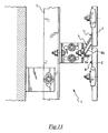
- the free end of the inclined web 11 forms a hook 15 suitable for engaging the edge of a through hole 18 provided in the outer wall of the top portion L2 of the supporting profile section 4.
- Figures 10a, 10b and 10c illustrate the correct sequence for effecting the fixing of a cladding slab 2 to the framework 6.
- the insertion of the anchorage portion of the upper anchorage member 8 into the hollow profile of the supporting profile section 4 must necessarily take place while the slab in question is rotated with respect to the vertical as illustrated in Figure 10a .
- the dimension of the opening 14 of the hollow profile of the supporting profile section 4 is less than the length of the web of the profile section 8b.
- the cladding slab may be rotated as far as the vertical position illustrated in Figure 10b , having as a pivot for the rotation the supporting profile section 4 in which the anchorage portion of the upper anchorage member 8 is inserted.
- any further rotation of the cladding slab 2 towards the wall W which is to be clad is prevented by the fact that the rear portion of the cladding slab comes into abutment against the front portion L3 of the supporting profile section 4 shown lower down.
- the aforesaid rotation of the cladding slab 2 with respect to the supporting profile section 4 causes the profile section web 8b of the anchorage portion of the upper anchorage member 8 to interfere with the inner part of the front portion L3 of the supporting profile section 4.
- the interference established during the aforesaid rotation causes the anchorage portion of the upper anchorage member 8 to load itself like a spring and to act against the inner walls of the hollow profile section with a predetermined load, an indication of secure retention of the anchorage portion of the upper anchorage member in the supporting profile section 4.
- This descending movement has an advantageous effect, i.e. the inclined web 11a of the lower anchorage member 11 then interferes with the inclined top portion L2 of the supporting profile section 4, preventing the lower end of the cladding slab 2 from (detaching itself from?) the supporting profile section 4 shown lower down in Figure 10C .
- the support structure for slabs for cladding a wall which is to be clad makes it possible to satisfy the aforesaid requirements and at the same time remedy the drawbacks mentioned in the introduction of the description with reference to the prior art.
- the application of the cladding slabs 2 may be carried out in a simple, rapid and precise manner without the aid of any other external element, subject to the fixing of the anchorage members to the cladding slabs. This application is executed.
- Another advantage of the support structure and of the cladding structure according to the present invention lies in the fact that the anchorage members may be fixed to the cladding slabs in the workshop, so that on site it will be sufficient to arrange for the fixing of the framework to the wall to be clad and for the subsequent application of the cladding slabs.
Abstract
Support structure for cladding slabs (2) for cladding a wall (W) comprises: a supporting profile section (4) suitable for forming a stringer of a framework with a front side facing towards the cladding slabs; an upper anchorage member (8) and a lower anchorage member adapted to be fixed to a cladding slab (2) and to be anchored to the supporting profile section (4). The supporting profile section is hollow and accessible from the front of the supporting profile section via an opening (14), an anchorage portion (8a,8b) of the upper anchorage member is inserted into the supporting profile section via said opening in order to anchor the upper anchorage member to said supporting profile section, and an anchorage portion (11a) of said lower anchorage member bears from the outside on said hollow profile of the supporting profile section to anchor the lower anchorage member to said supporting profile section.
Description
- The present invention relates to a support structure for cladding slabs for cladding a wall which is to be clad according to the preamble of
claim 1. - More specifically, the present invention relates to a support structure for wall cladding, in particular for cladding for ventilated walls arranged to allow the circulation of air within the air gap which is formed by the cladding material and the actual wall structure which is to be covered.
- The support structure comprises a support framework and anchorage members intended to hook onto the framework, the framework being intended to be fixed to the wall which is to be clad, while the anchorage members are fixable to the cladding slabs.
- In the building sector, the use of cladding walls supported by a support structure, such as ventilated walls, is nowadays increasingly widespread, particularly in the production of newly constructed buildings, inasmuch as it makes it possible to clad wall structures of large dimensions in a rapid and durable manner. The advantages arising from the use of ventilated walls mainly lie in the capacity for protecting the underlying wall structure from adverse weather conditions, ensuring correct ventilation thereof, and permitting the maximum amount of freedom in the choice of cladding material to be used.
- Since the use of cladding walls supported by a support structure is very much in demand, it is necessary to consider that the operation of fixing the framework and the subsequent operation of applying the cladding to the framework may prove to be somewhat difficult. Consequently, in order to avoid inaccuracies in the installed product it is advisable for the aforesaid operations to be carried out by specialised personnel, with an obvious increase in the installation costs.
- In the field of walls with ventilated cladding there is therefore a great need to have available a support structure, for slabs for cladding a wall which is to be clad, which is simple and quick to install, having characteristics such as to avoid as far as possible any errors in the positioning of the individual cladding slabs. At the same time, it should also be ensured that it is possibe to dismantle the individual cladding slabs that are damaged, have deteriorated over time, or are not correctly positioned with respect to the framework.
- A further requirement is that of allowing the maximum degree of freedom of finishing of the cladding wall, for example, allowing the positioning of the slabs in such a way that a joint line of predetermined width becomes visible between the slabs, optionally capable of being stuccoed and/or sealed so as to impart to the cladding wall the appearance of a wall associated with the wall structure by adhesive means or other similar techniques.
- With regard to the anchorage members, these should be capable of satisfying numerous requirements, among which are:
- the possibility of absolute and secure connection to the framework even in the case of high loads of the slab to be supported and/or of vibrations or impacts;
- the possibility of acting on the framework so as to take up any play or dimensional inaccuracies and,
- the possibility of being snap-connected or similarly connected to the framework.
The problem underlying the present invention is that of devising a support structure for slabs for cladding a wall which is to be clad, having structural and functional characteristics such as to satisfy the aforesaid requirements, and at the same time remedying the drawbacks mentioned with reference to the prior art.
This problem is solved by a support structure for slabs for cladding a wall which is to be clad according to the characteristics ofclaim 1.
Other characteristics and advantages of the support structure for slabs for cladding a wall which is to be clad according to the present invention will become clear from the following description of some preferred exemplary embodiments thereof, provided by way of non-limiting example with reference to the appended drawings, in which: -Figure 1 shows a diagrammatic perspective view of the front of a cladding structure according to the invention comprising a support structure according to the invention and cladding slabs; -
Figure 2 shows a view in cross-section of the cladding structure ofFigure 1 , in which can be seen the support structure according to the invention when supporting the cladding slabs; -
Figure 3 shows a simplified exploded view of the support structure ofFigure 2 ; -
Figure 4 shows a perspective view of the back of a cladding slab with the upper and lower anchorage members of the support structure according to the invention fixed thereto; -
Figure 5 shows a perspective view of the back of a portion of the cladding structure ofFigure 1 ; -
Figure 6 shows a view in cross-section of the supporting profile section used in the support structure illustrated inFigure 2 ; -
Figures 7, 8 and 9 show some possible alternative embodiments of the supporting profile section ofFigure 6 ; -
Figures 10a, 10b and 10c illustrate a sequence for fitting the cladding slab ofFigure 4 to the support structure according to the invention; -
Figures 11 ,12 and13 show possible alternative embodiments of the support structure ofFigure 2 , -
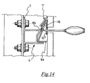
Figure 14 illustrates a sequence of the step for removal of a cladding slab from the support structure ofFigure 12 , and -
Figures 15 and 16 show the support structure according to the invention when supporting the cladding slabs according to an embodiment with ventilation and, respectively, without ventilation of the air gap between the cladding wall and the wall which is to be clad. - With reference to the appended drawings, the
reference 1 indicates as a whole a support structure according to the invention for supporting acladding structure 3 for cladding a wall W which is to be clad. - The
support structure 1 comprises a load-bearingframework 6 intended to be fixed to the wall W in order to support thecladding structure 3. - The
cladding structure 3 comprises a plurality ofcladding slabs 2 arranged alongside one another to form a wall which is substantially continuous except for optional joint lines between thecladding slabs 2, as illustrated inFigures 1 and5 . - In the example illustrated, the aforesaid load-bearing framework comprises a plurality of
uprights 5 arranged parallel to and equidistant from one another and suitable for supporting a plurality ofstringers 4. - Each
stringer 4 is in the form of a supporting profile section extending in a predetermined longitudinal direction X-X and comprises: a rear portion 4b suitable for permitting fixing to the wall W and afront portion 4a facing towards thecladding slabs 2 to be supported. - Preferably, the supporting
profile section 4 is made of aluminium or another metallic material, for example a stainless steel, it being also possible to use materials of another type, for example a plastics material. Generally, the choice of material to be used for the production of the aforesaid supporting profile section should be made by taking into consideration the weight of the slabs of cladding material to be supported. However, in the case where the choice falls on aluminium, the supporting profile section may be produced by extrusion (Figures 6, 7 and 8 ) while in the case where a stainless steel is chosen, the supporting profile section may be produced by shearing and bending, starting from a sheet of suitable thickness (Figure 9 ). - In the examples of
Figures 2 ,11 and12 , the rear portion 4b of the supportingprofile section 4 which forms the stringer is configured so as to form aflange 7 via which fixing to theuprights 5 can be carried out, for example by means of bolts, screws, welding and/or other forms of connection known per se. - As an alternative to what has been described above, each
stringer 4 may be fixed directly to the wall W which is to be clad by means of nogs, screws, rivets or other equivalent fixing means, so that the flange of the rear part of the stringer may be embedded or inserted into the wall W which is to be clad, during its production. In this case theframework 6 will be formed only by thestringers 4. - Independently of the embodiments illustrated, it is useful to note that the system for fixing the
stringers 4 to theuprights 5 may provide for fixing means capable of permitting adjustment both in a vertical direction and for coming closer to/further away from the wall W which is to be clad. - In relation to the
cladding slabs 2 it should be stated that these may be elements such as flat slabs, tiles, small bricks, cladding panels or similar elements of any suitable material. In the examples ofcladding slabs 4 illustrated they have a square configuration, it being however possible to provide for the use of cladding slabs having different shapes. - The
support structure 1 and thecladding slabs 2 supported by that support structure together form a complementary wall of cladding rigidly fixed to the wall W which is to be clad. - Besides the supporting
profile section 4, thesupport structure 2 includes anupper anchorage member 8 and alower anchorage member 11, which members, after being fixed to the back of acladding slab 2, are suitable for being anchored to theprofile sections 4 to effect the support of said cladding slabs on theframework 6. -
Figure 4 illustrates acladding slab 2 to which the aforesaid upper 8 and lower 11 anchorage members have been fitted. The example shows an optimum situation which provides for the use of twoupper anchorage members 8 fixed in proximity to the upper edge of thecladding slab 2 and of two correspondinglower anchorage members 11 fixed in proximity to the lower edge of thecladding slab 2, it being clear that, depending on the specific requirements, the number and positioning of the aforesaid anchorage members may be conveniently varied. Thus, for example, for particularly heavy cladding slabs it is possible to provide for a greater number of anchorage members. - The manner in which the
anchorage members cladding slabs 2 may be of any type, it being possible to provide for the use of adhesives and mastics, as well as expansion bolts or other equivalent systems. Theanchorage members - According to a preferred embodiment, the
anchorage members - Each supporting
profile section 4 of theframework 6, when it is utilised in such a way as to take on the function of a stringer, as illustrated inFigure 2 , comprises afront portion 4a facing towards thecladding slabs 2 and which, with reference to its cross-section, forms a hollow profile accessible from the front of the supportingprofile section 4 via an opening 14. - With particular reference to the cross-section of the supporting
profile section 4, this latter comprises: - a bottom portion L1 which forms a vertical abutment,
- a top portion L2 facing the bottom portion L1 and connected thereto via a connecting portion L4, and
- a front portion L3 which extends from the front end of the upper side L2 substantially approaching the bottom portion L1.
- The aforesaid opening 14 is thus formed between the front portion L3 and the bottom portion L1 as can be clearly seen from
Figures 6 to 9 . - It should be noted that the top portion L2 of the supporting
profile section 4 is inclined at a predetermined angle A in such a way as to form an acute angle with the front portion L3 and, at the same time, to form with respect to the vertical a plane inclined away from thecladding slabs 2 supported. - Advantageously, the front portion L3 of the supporting
profile section 4 extends in a vertical plane and forms a vertical locating plane against which the back of the cladding slab rests. - With particular reference to
Figures 15 and 16 , it is clear that by conveniently varying upwards or downwards the fixing point of theanchorage members profile section 4 is located so as to bridge (Figure 15 ) or not to bridge (Figure 16 ) the horizontal joint line formed between two consecutive cladding slabs with reference to the vertical direction. This makes it possible to produce cladding walls of the closed chamber type in the first case or ventilated chamber type in the second case. - Advantageously, an anchorage portion of the
upper anchorage member 8 is inserted into said hollow profile of the supporting profile section via the opening 14, so as to effect the anchorage of theupper anchorage member 8 to the supportingprofile section 4. - More specifically, the anchorage portion of the
upper anchorage member 8 bears against the aforesaid bottom portion L1 of the supportingprofile section 4 and interferes from inside with the front portion L3 of the supportingprofile section 4, thus being retained inside the hollow profile of the supportingprofile section 4. - The aforesaid anchorage portion of the
upper anchorage member 8 comprises alower portion 8a configured so as to form an interlocking fit with the inner wall of the bottom portion L1 of the supportingprofile section 4, and anupper portion 8b which is adapted to act against the inner wall of the front portion L3, abutting against it. - According to the preferred embodiment, the
upper anchorage member 8 is a profile section and: - the
lower portion 8a is a portion of profile section configured so as to mate with the aforesaid bottom portion L1 of the supportingprofile section 4, and - the
upper portion 8b is in the form of a profile section web which extends from thelower portion 8a in order to contact with its head end the inner wall of the front portion L3 of the supportingprofile section 4. - As can be seen from the drawings, an acute angle is formed between the
profile section web 8b and thelower portion 8b of theupper anchorage member 8. According to a preferred embodiment (Figures 7, 8 11 ,12 and14 ) the inner wall of the front portion L3 of the supportingprofile section 4 comprises a set of teeth L3 oriented downwards, i.e. towards the bottom portion L1 of the supportingprofile section 4, and suitable for opposing the displacement of theprofile section web 8b towards the top portion L2 of the supportingprofile section 4. - Advantageously, the
profile section web 8b of theupper anchorage member 8 extends for a length greater than the dimension of the opening 14 of the supporting profile section measured in the cross-section of the supporting profile section itself. - According to a preferred embodiment, in the front portion L3 of the supporting profile section there is a through hole 10 (
Figure 7, 8 ,11 ,12 ,13 and14 ) to make it possible to act with a tool on the anchorage portion of the upper anchorage member at the front of the support structure. - With regard to the
lower anchorage member 11, it should be noted that this has ananchorage portion 11 a which is adapted to bear from the outside on the hollow profile of the supportingprofile section 4, so as to ensure convenient bearing anchorage of thelower anchorage member 11 on the supportingprofile section 4. - More specifically, as can be seen from the drawings, the
aforesaid anchorage portion 11 a of thelower anchorage member 11 comes to bear from the outside on the top portion L2 of the supportingprofile section 4. - In the preferred exemplary embodiment, the
lower anchorage member 11 is in the form of a profile section and theaforesaid anchorage portion 11a is in the form of an inclined web which extends towards the wall W which is to be clad. - In particular, the
inclined web 11a of thelower anchorage member 11 is inclined with respect to the vertical so as to form an acute angle and to diverge downwards with respect to the cladding slabs (2) supported by theframework 6. - Preferably, the inclination of the
inclined web 11a coincides with the inclination of the top portion L2 of the supportingprofile section 4. - According to a preferred embodiment, the free end of the
inclined web 11 a of thelower anchorage member 11a is configured so as to engage in the manner of a hook a corresponding recess of the top portion L2 of the supportingprofile section 4. - According to the embodiment illustrated in
Figure 11 , the free end of theinclined web 11 a forms a hook 15 suitable for engaging a small tooth present in the outer wall of the top portion L2 of the supportingprofile section 4. - In a different way, according to the embodiment of
Figure 12 , the free end of theinclined web 11 forms a hook 15 suitable for engaging the edge of a throughhole 18 provided in the outer wall of the top portion L2 of the supportingprofile section 4. -
Figures 10a, 10b and 10c illustrate the correct sequence for effecting the fixing of acladding slab 2 to theframework 6. In particular, the insertion of the anchorage portion of theupper anchorage member 8 into the hollow profile of the supportingprofile section 4 must necessarily take place while the slab in question is rotated with respect to the vertical as illustrated inFigure 10a . This is due to the fact that, as stated, the dimension of the opening 14 of the hollow profile of the supportingprofile section 4 is less than the length of the web of theprofile section 8b. - Once the anchorage portion of the
upper anchorage member 8 has been inserted into the hollow profile of the supportingprofile section 4, the cladding slab may be rotated as far as the vertical position illustrated inFigure 10b , having as a pivot for the rotation the supportingprofile section 4 in which the anchorage portion of theupper anchorage member 8 is inserted. On reaching the position illustrated inFigure 10b , any further rotation of thecladding slab 2 towards the wall W which is to be clad is prevented by the fact that the rear portion of the cladding slab comes into abutment against the front portion L3 of the supportingprofile section 4 shown lower down. - It should be noted that the aforesaid rotation of the
cladding slab 2 with respect to the supportingprofile section 4 causes theprofile section web 8b of the anchorage portion of theupper anchorage member 8 to interfere with the inner part of the front portion L3 of the supportingprofile section 4. The interference established during the aforesaid rotation causes the anchorage portion of theupper anchorage member 8 to load itself like a spring and to act against the inner walls of the hollow profile section with a predetermined load, an indication of secure retention of the anchorage portion of the upper anchorage member in the supportingprofile section 4. - At this point it is sufficient to allow the
cladding slab 2 to descend until thelower portion 8a of the upper anchorage member comes to bear against the lower abutment formed by the bottom portion L1 of the supportingprofile section 4 shown at the top inFigure 10c . - This descending movement has an advantageous effect, i.e. the
inclined web 11a of thelower anchorage member 11 then interferes with the inclined top portion L2 of the supportingprofile section 4, preventing the lower end of thecladding slab 2 from (detaching itself from?) the supportingprofile section 4 shown lower down inFigure 10C . - It should be noted that in the position shown in
Figure 10c , it is the actual weight of thecladding slab 2 which keeps this latter at the bottom of the downward travel, thus preventing any possibility of the slab being able to detach itself from the framework. At the same time, theupper anchorage members 8 remain biased with a predetermined resilient load in such a way as to exclude any likelihood of their being able to come out of the hollow profile of thesupport member 4 in which they are inserted. - It should be noted that in the case where a safety mesh is applied to the back of the cladding slabs the
cladding slab 2 remains attached to the framework even in the event of the physical integrity of the cladding slab itself becoming compromised. - If this should occur, when it is desired to remove the cladding slabs it is sufficient to raise them up by a few centimetres and rotate them with respect to the
framework 6 so as to bring them back into the position illustrated inFigure 10a , in which it is finally possible to disengage theupper anchorage members 8 from the hollow profile 14 of the supportingprofile section 4 and remove the cladding slab from the framework. - The operation of removal of the cladding slabs is in any case facilitated if there is in the front portion L3 of the supporting
profile sections 4 the throughhole 10, by means of which it is possible to act on theprofile section web 8b from the outside of the cladding wall by means of a tool, as illustrated inFigure 14 . This causes theprofile section web 8b to be pulled back towards the rear portion L4 of the supportingprofile section 4 even in the presence of theteeth 12. As can be seen fromFigure 14 , the aforesaid pulling back of theprofile section web 8b towards the rear portion L4 of the supportingprofile section 4 causes theprofile section web 8b to act via the throughhole 18 also on theinclined web 11 of the lower anchorage means 11 of the cladding slab placed immediately above, permitting the disengagement of the respective hook 15 from the edge of the throughhole 18. - As may be appreciated from what has been described, the support structure for slabs for cladding a wall which is to be clad according to the present invention makes it possible to satisfy the aforesaid requirements and at the same time remedy the drawbacks mentioned in the introduction of the description with reference to the prior art. In fact, once the
support structure 1 has been fixed to the wall W which is to be clad, the application of thecladding slabs 2 may be carried out in a simple, rapid and precise manner without the aid of any other external element, subject to the fixing of the anchorage members to the cladding slabs. This application is executed. - Another advantage of the support structure and of the cladding structure according to the present invention lies in the fact that the anchorage members may be fixed to the cladding slabs in the workshop, so that on site it will be sufficient to arrange for the fixing of the framework to the wall to be clad and for the subsequent application of the cladding slabs.
- Further advantages of the support structure and of the cladding structure according to the present invention include the possibility of:
- being able to dismantle the individual cladding slabs for any replacement or inspection operations,
- reducing to a minimum the number of uprights required,
- arranging the cladding slabs in columns or staggered with respect to one another,
- being able to produce the support members from aluminium or stainless steel,
- being able to produce the support members by extrusion or by shearing and bending, reducing to a minimum the need for processing by machine tools;
- simplicity of installation and removal;
- it is possible to produce cladding walls with cladding slabs staggered with respect to one another;
- it is possible to carry out the stuccoing or the sealing of the joints between the cladding slabs placed side by side;
- the anchorage of the cladding slabs is ensured even in the case of vibration.
- Naturally, in order to satisfy contingent and specific requirements, a person skilled in the art may apply to the support structure according to the invention many modifications and variants, all, however, contained within the scope of protection of the invention as defined by the appended claims.
Claims (23)
- A support structure (1) for slabs (2) for cladding a wall (W) which is to be clad, comprising:- a supporting profile section (4) suitable for forming a stringer of a framework and having a front side facing towards the cladding slabs (2) to be supported,- a first anchorage member (8) adapted to be fixed to a cladding slab (2), and- a second anchorage member (11) adapted to be fixed to a cladding slab (2), said first anchorage member (8) and said second anchorage member (11) being adapted to be anchored to said supporting profile section (4), characterized in that, when said supporting profile section (4) is positioned to form a stringer of said framework (6), at least a front portion (4a), facing towards the cladding slabs (2), of said supporting profile section (4) forms in cross-section a hollow profile accessible from the front of the supporting profile section (4) via an opening (14), said cross-section of the supporting profile section (4) comprising:wherein, when said supporting profile section (4) is positioned to form a stringer of said framework (6):- a bottom portion (L1) which forms a vertical abutment,- a top portion (L2) connected to said bottom portion (L1) and facing this latter,- a front portion (L3) extending from said top portion (L2) substantially approaching said bottom portion (L1), said opening (14) being formed between said front portion (L3) and said bottom portion (L1),- an anchorage portion (8a, 8b) of said first anchorage member (8) is inserted into said hollow profile of the supporting profile section (4) via said opening (14) to effect the anchorage of said first anchorage member (8) to said supporting profile section (4), said anchorage portion (8a, 8b) coming to bear on said bottom portion (L1) of the supporting profile section (4) and interfering with said front portion (L3) of the supporting profile section (4) in order to be retained in said hollow profile of the supporting profile section (4),- an anchorage portion (11a) of said second anchorage member (11) bearing from the outside on said hollow profile of the supporting profile section (4) in order to effect the anchorage of said second anchorage member (11) to said supporting profile section (4).
- A support structure (1) according to claim 1, wherein said bottom portion (L1) and said top portion (L2) of the supporting profile section (4) are connected by a rear portion (L4).
- A support structure (1) according to claim 1 or 2, wherein said top portion (L2) of the supporting profile section (4) is inclined by a predetermined angle (A) in such a way as to form an acute angle with said front portion (L3) of the supporting profile section (4) and to form with respect to the vertical a plane inclined away from the cladding slabs (2) to be supported.
- A support structure (1) according to any one of claims 1 to 3, wherein said front portion (L3) of the supporting profile section (4) comprises a through hole (10), to make it possible to act with a tool on said anchorage portion (8b) of said first anchorage member (8) at the front of the support structure (1).
- A support structure (1) according to any one of claims 1 to 4, wherein said front portion (L3) of the supporting profile section (4) extends in a vertical plane to constitute a bearing abutment for the cladding slabs (2) supported.
- A support structure (1) according to any one of claims 1 to 5, wherein said supporting profile section (4) comprises a rear portion via which it can be fixed directly or indirectly to the wall (W) which is to be clad.
- A support structure (1) according to any one of claims 1 to 6, wherein said anchorage portion (8a, 8b) of said first anchorage member (8) has a lower portion (8a) bearing on said bottom portion (L1) of the supporting profile section (4) and an upper portion (8b) which presses from inside against said front portion (L3) of the supporting profile section (4), abutting against this latter.
- A support structure (1) according to claim 7, wherein said lower portion (8a) of said anchorage portion of said first anchorage member (8) is configured so as to form an interlocking fit with said bottom portion (L1) of the supporting profile section (4).
- A support structure (1) according to claim 7 or claim 8, wherein said first anchorage member (8) is a profile section.
- A support structure (1) according to claim 9, wherein:- said lower portion (8a) of said anchorage portion of said first anchorage member (8) is a portion of profile section configured so as to mate with said bottom portion (L1) of the supporting profile section (4), and- said upper portion (8b) of said anchorage portion of said first anchorage member (8) comprises a profile section web which extends from said lower portion of the anchorage portion until it contacts said front portion (L3) of the supporting profile section (4).
- A support structure (1) according to claim 10, wherein said profile section web (8b) forms an acute angle with said lower portion of said anchorage portion of said first anchorage member (8).
- A support structure (1) according to claim 10 or claim 11, wherein said profile section web (8b) abuts with a free end thereof against said front portion (L3) of the supporting profile section (4).
- A support structure (1) according to claim 12, wherein the inner wall of said front portion (L3) of the supporting profile section (4) comprises a set of teeth (12) oriented towards said bottom portion (L1) of the supporting profile section (4) so as to oppose the displacement of said profile section web (8b) towards the top portion (L2) of the supporting profile section (4).
- A support structure (1) according to any one of claims 10 to 13, wherein said profile section web (8b) extends for a length greater than the dimension of the opening (14) of the supporting profile section (4) measured in the cross-section of the supporting profile section (4) itself.
- A support structure (1) according to any one of claims 1 to 14, wherein said anchorage portion (11a) of said second anchorage member (11) bears from the outside on said top portion (L2) of the support profile section (4).
- A support structure (1) according to claim 15 or to any one of claims 1 to 14,
wherein said second anchorage member (11) is a profile section and said anchorage portion of said second anchorage member (11) is a web (11a) which extends towards the wall (W) which is to be clad. - A support structure (1) according to claim 16, wherein said web (11a) of said second anchorage member (11) extends towards the wall (W) which is to be clad so as to form with respect to the vertical an inclined plane diverging downwards from the cladding slab (2) supported.
- A support structure (1) according to claim 16 or claim 17, wherein the free end of said web (11a) of said second anchorage member (11) comprises hook means (15) adapted to engage a corresponding recess (16) of the supporting profile section (4).
- A cladding structure for a wall (W) which is to be clad, comprising a framework (6) that can be fixed to the wall (W) which is to be clad and a plurality of cladding slabs (2) supported by said framework (6), wherein:- said framework (6) comprises a plurality of horizontal stringers formed by supporting profile sections (4) according to any one of claims 1 to 18, and- at least a first anchorage member (8) and a second anchorage member (11) are rigidly fixed to each cladding slab (2), characterized in that said first anchorage member (8) is inserted into said hollow profile of the supporting profile section (4) of the framework (6) and, at the same time, said second anchorage member (11) of the same cladding slab (2) bears from the outside on a hollow profile of an underlying supporting profile section (4) of the framework (6).
- A cladding structure according to claim 19, wherein said first anchorage member (8) is fixed to a cladding slab (2) so that it is above said second anchorage member (11) when said cladding slab (2) is supported by the framework (6).
- A cladding structure according to claim 19 or claim 20, wherein said first anchorage member (8) and said second anchorage member (11) are fixed to the back of said cladding slabs (2).
- A cladding structure according to claim 21, wherein said front portion (L3) of the supporting profile section (4) constitutes a bearing abutment for the back of the cladding slab (2).
- A cladding structure according to any one of claims 19 to 22, wherein said front portion (L3) of the supporting profile section (4) bridges the horizontal joint lines between two consecutive cladding slabs with reference to a vertical direction.
Applications Claiming Priority (1)
| Application Number | Priority Date | Filing Date | Title |
|---|---|---|---|
| ITMI20070395 ITMI20070395A1 (en) | 2007-02-28 | 2007-02-28 | SUPPORT STRUCTURE FOR A WALL COVERING SHEETS TO BE COVERED. |
Publications (1)
| Publication Number | Publication Date |
|---|---|
| EP1965002A2 true EP1965002A2 (en) | 2008-09-03 |
Family
ID=39486608
Family Applications (1)
| Application Number | Title | Priority Date | Filing Date |
|---|---|---|---|
| EP20080002813 Withdrawn EP1965002A2 (en) | 2007-02-28 | 2008-02-15 | Support structure for slabs for cladding a wall to be clad |
Country Status (4)
| Country | Link |
|---|---|
| EP (1) | EP1965002A2 (en) |
| CN (1) | CN101255762A (en) |
| EA (1) | EA200800445A1 (en) |
| IT (1) | ITMI20070395A1 (en) |
Families Citing this family (1)
| Publication number | Priority date | Publication date | Assignee | Title |
|---|---|---|---|---|
| CN102633179B (en) * | 2012-04-27 | 2014-03-19 | 柏文元 | Inserting and hanging type decorative component for decoration in elevator car |
-
2007
- 2007-02-28 IT ITMI20070395 patent/ITMI20070395A1/en unknown
-
2008
- 2008-02-15 EP EP20080002813 patent/EP1965002A2/en not_active Withdrawn
- 2008-02-27 EA EA200800445A patent/EA200800445A1/en unknown
- 2008-02-28 CN CNA2008100820397A patent/CN101255762A/en active Pending
Also Published As
| Publication number | Publication date |
|---|---|
| ITMI20070395A1 (en) | 2008-09-01 |
| EA200800445A1 (en) | 2008-08-29 |
| CN101255762A (en) | 2008-09-03 |
Similar Documents
| Publication | Publication Date | Title |
|---|---|---|
| US8365481B2 (en) | Anchorage system of ventilated facades | |
| US20220205251A1 (en) | Support bracket apparatus | |
| KR100827716B1 (en) | Bracket for window and door frames | |
| US20060032157A1 (en) | Seismic wall system | |
| WO2010012061A1 (en) | Clip and support for installing cladding | |
| US20100242403A1 (en) | Multiple dimension beam, deck and column system | |
| CN114341445B (en) | Outer plate arrangement structure | |
| US20100024347A1 (en) | Clamp | |
| EP1965002A2 (en) | Support structure for slabs for cladding a wall to be clad | |
| EP1918481A2 (en) | Ventilated wall comprising support elements and cladding structure thereof | |
| EP3179008A1 (en) | Brick siding system | |
| KR101275932B1 (en) | Method for installing ALC panel to concrete slab | |
| RU2307906C2 (en) | Method for vented building face assemblage and enveloping structure for method realization | |
| RU2735006C1 (en) | Device for mounting large-size suspended facing panels | |
| KR101940861B1 (en) | Deck plate and deck plate system | |
| EP3219869B1 (en) | Fastener and wall element of building | |
| RU2616951C1 (en) | Device for concealed fixing of facing panel in mounted ventilated facade | |
| US11248374B2 (en) | Facade support system | |
| JP2008008112A (en) | Partition wall | |
| CA3049211A1 (en) | Systems for recessing subfloor structures | |
| CN1973102A (en) | Wall face exterior structure of outer wall face insulation building and its wall face exterior furring, lateral furring strip frame for installing wall face exterior material and wall face exterior fo | |
| CN213013896U (en) | Expansion joint device for bridge construction | |
| NL2029428B1 (en) | Brick slip wall cladding system | |
| KR20180131058A (en) | Spacing masonry type Brick wall and construction method thereof | |
| JP7040755B2 (en) | Outer wall structure |
Legal Events
| Date | Code | Title | Description |
|---|---|---|---|
| PUAI | Public reference made under article 153(3) epc to a published international application that has entered the european phase |
Free format text: ORIGINAL CODE: 0009012 |
|
| AK | Designated contracting states |
Kind code of ref document: A2 Designated state(s): AT BE BG CH CY CZ DE DK EE ES FI FR GB GR HR HU IE IS IT LI LT LU LV MC MT NL NO PL PT RO SE SI SK TR |
|
| AX | Request for extension of the european patent |
Extension state: AL BA MK RS |
|
| STAA | Information on the status of an ep patent application or granted ep patent |
Free format text: STATUS: THE APPLICATION IS DEEMED TO BE WITHDRAWN |
|
| 18D | Application deemed to be withdrawn |
Effective date: 20100831 |