EP1964950A2 - Procédé de coupe de filaments déroulés et lames de coupe à surfaces traitées - Google Patents
Procédé de coupe de filaments déroulés et lames de coupe à surfaces traitées Download PDFInfo
- Publication number
- EP1964950A2 EP1964950A2 EP20080003625 EP08003625A EP1964950A2 EP 1964950 A2 EP1964950 A2 EP 1964950A2 EP 20080003625 EP20080003625 EP 20080003625 EP 08003625 A EP08003625 A EP 08003625A EP 1964950 A2 EP1964950 A2 EP 1964950A2
- Authority
- EP
- European Patent Office
- Prior art keywords
- diamond
- nitride
- carbide
- titanium
- carbon
- Prior art date
- Legal status (The legal status is an assumption and is not a legal conclusion. Google has not performed a legal analysis and makes no representation as to the accuracy of the status listed.)
- Granted
Links
- 238000000034 method Methods 0.000 title claims abstract description 34
- OKTJSMMVPCPJKN-UHFFFAOYSA-N Carbon Chemical compound [C] OKTJSMMVPCPJKN-UHFFFAOYSA-N 0.000 claims abstract description 40
- 229910052799 carbon Inorganic materials 0.000 claims abstract description 40
- 239000000835 fiber Substances 0.000 claims abstract description 35
- 239000000463 material Substances 0.000 claims abstract description 35
- UONOETXJSWQNOL-UHFFFAOYSA-N tungsten carbide Chemical compound [W+]#[C-] UONOETXJSWQNOL-UHFFFAOYSA-N 0.000 claims abstract description 35
- 238000004513 sizing Methods 0.000 claims abstract description 28
- 239000000126 substance Substances 0.000 claims abstract description 20
- 229910003460 diamond Inorganic materials 0.000 claims abstract description 19
- 239000010432 diamond Substances 0.000 claims abstract description 19
- 239000000203 mixture Substances 0.000 claims abstract description 14
- NRTOMJZYCJJWKI-UHFFFAOYSA-N Titanium nitride Chemical compound [Ti]#N NRTOMJZYCJJWKI-UHFFFAOYSA-N 0.000 claims abstract description 13
- -1 carbon Chemical compound 0.000 claims abstract description 11
- 229910052582 BN Inorganic materials 0.000 claims abstract description 10
- PZNSFCLAULLKQX-UHFFFAOYSA-N Boron nitride Chemical compound N#B PZNSFCLAULLKQX-UHFFFAOYSA-N 0.000 claims abstract description 10
- 239000007788 liquid Substances 0.000 claims abstract description 10
- 238000000576 coating method Methods 0.000 claims description 20
- VYZAMTAEIAYCRO-UHFFFAOYSA-N Chromium Chemical compound [Cr] VYZAMTAEIAYCRO-UHFFFAOYSA-N 0.000 claims description 16
- RTAQQCXQSZGOHL-UHFFFAOYSA-N Titanium Chemical compound [Ti] RTAQQCXQSZGOHL-UHFFFAOYSA-N 0.000 claims description 16
- 239000011651 chromium Substances 0.000 claims description 16
- 229910052719 titanium Inorganic materials 0.000 claims description 16
- 239000010936 titanium Substances 0.000 claims description 16
- 239000011248 coating agent Substances 0.000 claims description 15
- 229910052804 chromium Inorganic materials 0.000 claims description 12
- 239000010941 cobalt Substances 0.000 claims description 12
- 229910017052 cobalt Inorganic materials 0.000 claims description 12
- 229910052735 hafnium Inorganic materials 0.000 claims description 12
- 239000010955 niobium Substances 0.000 claims description 12
- GUCVJGMIXFAOAE-UHFFFAOYSA-N niobium atom Chemical compound [Nb] GUCVJGMIXFAOAE-UHFFFAOYSA-N 0.000 claims description 12
- GUTLYIVDDKVIGB-UHFFFAOYSA-N cobalt atom Chemical compound [Co] GUTLYIVDDKVIGB-UHFFFAOYSA-N 0.000 claims description 11
- QYEXBYZXHDUPRC-UHFFFAOYSA-N B#[Ti]#B Chemical compound B#[Ti]#B QYEXBYZXHDUPRC-UHFFFAOYSA-N 0.000 claims description 8
- 229910052580 B4C Inorganic materials 0.000 claims description 8
- ZOKXTWBITQBERF-UHFFFAOYSA-N Molybdenum Chemical compound [Mo] ZOKXTWBITQBERF-UHFFFAOYSA-N 0.000 claims description 8
- 229910001257 Nb alloy Inorganic materials 0.000 claims description 8
- PXHVJJICTQNCMI-UHFFFAOYSA-N Nickel Chemical compound [Ni] PXHVJJICTQNCMI-UHFFFAOYSA-N 0.000 claims description 8
- VYPSYNLAJGMNEJ-UHFFFAOYSA-N Silicium dioxide Chemical compound O=[Si]=O VYPSYNLAJGMNEJ-UHFFFAOYSA-N 0.000 claims description 8
- 229910033181 TiB2 Inorganic materials 0.000 claims description 8
- GWEVSGVZZGPLCZ-UHFFFAOYSA-N Titan oxide Chemical compound O=[Ti]=O GWEVSGVZZGPLCZ-UHFFFAOYSA-N 0.000 claims description 8
- MCMNRKCIXSYSNV-UHFFFAOYSA-N Zirconium dioxide Chemical compound O=[Zr]=O MCMNRKCIXSYSNV-UHFFFAOYSA-N 0.000 claims description 8
- INAHAJYZKVIDIZ-UHFFFAOYSA-N boron carbide Chemical compound B12B3B4C32B41 INAHAJYZKVIDIZ-UHFFFAOYSA-N 0.000 claims description 8
- VBJZVLUMGGDVMO-UHFFFAOYSA-N hafnium atom Chemical compound [Hf] VBJZVLUMGGDVMO-UHFFFAOYSA-N 0.000 claims description 8
- 229910052751 metal Inorganic materials 0.000 claims description 8
- 239000002184 metal Substances 0.000 claims description 8
- 229910052750 molybdenum Inorganic materials 0.000 claims description 8
- 239000011733 molybdenum Substances 0.000 claims description 8
- 150000004767 nitrides Chemical class 0.000 claims description 8
- 229910052710 silicon Inorganic materials 0.000 claims description 8
- 239000010703 silicon Substances 0.000 claims description 8
- 229910010271 silicon carbide Inorganic materials 0.000 claims description 8
- HBMJWWWQQXIZIP-UHFFFAOYSA-N silicon carbide Chemical compound [Si+]#[C-] HBMJWWWQQXIZIP-UHFFFAOYSA-N 0.000 claims description 8
- GUVRBAGPIYLISA-UHFFFAOYSA-N tantalum atom Chemical compound [Ta] GUVRBAGPIYLISA-UHFFFAOYSA-N 0.000 claims description 8
- 229910003470 tongbaite Inorganic materials 0.000 claims description 8
- LEONUFNNVUYDNQ-UHFFFAOYSA-N vanadium atom Chemical compound [V] LEONUFNNVUYDNQ-UHFFFAOYSA-N 0.000 claims description 8
- 239000011230 binding agent Substances 0.000 claims description 6
- 230000001681 protective effect Effects 0.000 claims description 6
- WFKWXMTUELFFGS-UHFFFAOYSA-N tungsten Chemical compound [W] WFKWXMTUELFFGS-UHFFFAOYSA-N 0.000 claims description 6
- 229910052721 tungsten Inorganic materials 0.000 claims description 6
- 239000010937 tungsten Substances 0.000 claims description 6
- INZDTEICWPZYJM-UHFFFAOYSA-N 1-(chloromethyl)-4-[4-(chloromethyl)phenyl]benzene Chemical compound C1=CC(CCl)=CC=C1C1=CC=C(CCl)C=C1 INZDTEICWPZYJM-UHFFFAOYSA-N 0.000 claims description 4
- 229910001182 Mo alloy Inorganic materials 0.000 claims description 4
- 229910000990 Ni alloy Inorganic materials 0.000 claims description 4
- XUIMIQQOPSSXEZ-UHFFFAOYSA-N Silicon Chemical compound [Si] XUIMIQQOPSSXEZ-UHFFFAOYSA-N 0.000 claims description 4
- 229910001362 Ta alloys Inorganic materials 0.000 claims description 4
- WGLPBDUCMAPZCE-UHFFFAOYSA-N Trioxochromium Chemical compound O=[Cr](=O)=O WGLPBDUCMAPZCE-UHFFFAOYSA-N 0.000 claims description 4
- 229910000756 V alloy Inorganic materials 0.000 claims description 4
- UQZIWOQVLUASCR-UHFFFAOYSA-N alumane;titanium Chemical compound [AlH3].[Ti] UQZIWOQVLUASCR-UHFFFAOYSA-N 0.000 claims description 4
- PNEYBMLMFCGWSK-UHFFFAOYSA-N aluminium oxide Inorganic materials [O-2].[O-2].[O-2].[Al+3].[Al+3] PNEYBMLMFCGWSK-UHFFFAOYSA-N 0.000 claims description 4
- SJKRCWUQJZIWQB-UHFFFAOYSA-N azane;chromium Chemical compound N.[Cr] SJKRCWUQJZIWQB-UHFFFAOYSA-N 0.000 claims description 4
- 239000000919 ceramic Substances 0.000 claims description 4
- UFGZSIPAQKLCGR-UHFFFAOYSA-N chromium carbide Chemical compound [Cr]#C[Cr]C#[Cr] UFGZSIPAQKLCGR-UHFFFAOYSA-N 0.000 claims description 4
- 229910000423 chromium oxide Inorganic materials 0.000 claims description 4
- 239000002131 composite material Substances 0.000 claims description 4
- 229910044991 metal oxide Inorganic materials 0.000 claims description 4
- 150000004706 metal oxides Chemical class 0.000 claims description 4
- 229910052758 niobium Inorganic materials 0.000 claims description 4
- JMANVNJQNLATNU-UHFFFAOYSA-N oxalonitrile Chemical compound N#CC#N JMANVNJQNLATNU-UHFFFAOYSA-N 0.000 claims description 4
- 239000004810 polytetrafluoroethylene Substances 0.000 claims description 4
- 229920001343 polytetrafluoroethylene Polymers 0.000 claims description 4
- 238000003825 pressing Methods 0.000 claims description 4
- 235000012239 silicon dioxide Nutrition 0.000 claims description 4
- 239000000377 silicon dioxide Substances 0.000 claims description 4
- 229910052715 tantalum Inorganic materials 0.000 claims description 4
- 239000004408 titanium dioxide Substances 0.000 claims description 4
- MTPVUVINMAGMJL-UHFFFAOYSA-N trimethyl(1,1,2,2,2-pentafluoroethyl)silane Chemical compound C[Si](C)(C)C(F)(F)C(F)(F)F MTPVUVINMAGMJL-UHFFFAOYSA-N 0.000 claims description 4
- 229910052720 vanadium Inorganic materials 0.000 claims description 4
- ZVWKZXLXHLZXLS-UHFFFAOYSA-N zirconium nitride Chemical compound [Zr]#N ZVWKZXLXHLZXLS-UHFFFAOYSA-N 0.000 claims description 4
- 150000001247 metal acetylides Chemical class 0.000 claims description 3
- 230000002378 acidificating effect Effects 0.000 abstract description 2
- 230000007935 neutral effect Effects 0.000 abstract 1
- 230000008020 evaporation Effects 0.000 description 10
- 238000001704 evaporation Methods 0.000 description 10
- 229910001220 stainless steel Inorganic materials 0.000 description 10
- 239000010935 stainless steel Substances 0.000 description 10
- 239000003365 glass fiber Substances 0.000 description 8
- 229910000975 Carbon steel Inorganic materials 0.000 description 7
- 239000010962 carbon steel Substances 0.000 description 7
- 238000005229 chemical vapour deposition Methods 0.000 description 6
- 230000014759 maintenance of location Effects 0.000 description 5
- 239000002253 acid Substances 0.000 description 4
- 229920001971 elastomer Polymers 0.000 description 4
- 238000010894 electron beam technology Methods 0.000 description 4
- 238000005240 physical vapour deposition Methods 0.000 description 4
- 229920002635 polyurethane Polymers 0.000 description 4
- 239000004814 polyurethane Substances 0.000 description 4
- 238000000859 sublimation Methods 0.000 description 4
- 230000008022 sublimation Effects 0.000 description 4
- 238000004519 manufacturing process Methods 0.000 description 3
- ATJFFYVFTNAWJD-UHFFFAOYSA-N Tin Chemical compound [Sn] ATJFFYVFTNAWJD-UHFFFAOYSA-N 0.000 description 2
- 239000004063 acid-resistant material Substances 0.000 description 2
- 230000008901 benefit Effects 0.000 description 2
- 238000000151 deposition Methods 0.000 description 2
- 230000008021 deposition Effects 0.000 description 2
- 239000000806 elastomer Substances 0.000 description 2
- 239000013536 elastomeric material Substances 0.000 description 2
- 238000010891 electric arc Methods 0.000 description 2
- 238000007733 ion plating Methods 0.000 description 2
- 238000001659 ion-beam spectroscopy Methods 0.000 description 2
- 238000010884 ion-beam technique Methods 0.000 description 2
- 238000000608 laser ablation Methods 0.000 description 2
- 239000002245 particle Substances 0.000 description 2
- 238000000623 plasma-assisted chemical vapour deposition Methods 0.000 description 2
- 238000005546 reactive sputtering Methods 0.000 description 2
- 238000004544 sputter deposition Methods 0.000 description 2
- 239000000758 substrate Substances 0.000 description 2
- XLYOFNOQVPJJNP-UHFFFAOYSA-N water Substances O XLYOFNOQVPJJNP-UHFFFAOYSA-N 0.000 description 2
- 238000012935 Averaging Methods 0.000 description 1
- JOYRKODLDBILNP-UHFFFAOYSA-N Ethyl urethane Chemical compound CCOC(N)=O JOYRKODLDBILNP-UHFFFAOYSA-N 0.000 description 1
- 239000011324 bead Substances 0.000 description 1
- 230000000694 effects Effects 0.000 description 1
- 230000003203 everyday effect Effects 0.000 description 1
- 239000011521 glass Substances 0.000 description 1
- 238000000227 grinding Methods 0.000 description 1
- MJIHNNLFOKEZEW-UHFFFAOYSA-N lansoprazole Chemical group CC1=C(OCC(F)(F)F)C=CN=C1CS(=O)C1=NC2=CC=CC=C2N1 MJIHNNLFOKEZEW-UHFFFAOYSA-N 0.000 description 1
- 238000003754 machining Methods 0.000 description 1
- 239000011159 matrix material Substances 0.000 description 1
- 230000002093 peripheral effect Effects 0.000 description 1
- 230000002028 premature Effects 0.000 description 1
- 238000012545 processing Methods 0.000 description 1
- 238000000926 separation method Methods 0.000 description 1
- 239000007858 starting material Substances 0.000 description 1
- 238000003860 storage Methods 0.000 description 1
- 238000012360 testing method Methods 0.000 description 1
- 239000012815 thermoplastic material Substances 0.000 description 1
Images
Classifications
-
- D—TEXTILES; PAPER
- D01—NATURAL OR MAN-MADE THREADS OR FIBRES; SPINNING
- D01G—PRELIMINARY TREATMENT OF FIBRES, e.g. FOR SPINNING
- D01G1/00—Severing continuous filaments or long fibres, e.g. stapling
- D01G1/02—Severing continuous filaments or long fibres, e.g. stapling to form staple fibres not delivered in strand form
- D01G1/04—Severing continuous filaments or long fibres, e.g. stapling to form staple fibres not delivered in strand form by cutting
-
- D—TEXTILES; PAPER
- D01—NATURAL OR MAN-MADE THREADS OR FIBRES; SPINNING
- D01G—PRELIMINARY TREATMENT OF FIBRES, e.g. FOR SPINNING
- D01G1/00—Severing continuous filaments or long fibres, e.g. stapling
- D01G1/06—Converting tows to slivers or yarns, e.g. in direct spinning
- D01G1/10—Converting tows to slivers or yarns, e.g. in direct spinning by cutting
-
- Y—GENERAL TAGGING OF NEW TECHNOLOGICAL DEVELOPMENTS; GENERAL TAGGING OF CROSS-SECTIONAL TECHNOLOGIES SPANNING OVER SEVERAL SECTIONS OF THE IPC; TECHNICAL SUBJECTS COVERED BY FORMER USPC CROSS-REFERENCE ART COLLECTIONS [XRACs] AND DIGESTS
- Y10—TECHNICAL SUBJECTS COVERED BY FORMER USPC
- Y10T—TECHNICAL SUBJECTS COVERED BY FORMER US CLASSIFICATION
- Y10T83/00—Cutting
- Y10T83/04—Processes
- Y10T83/0405—With preparatory or simultaneous ancillary treatment of work
- Y10T83/0443—By fluid application
Definitions
- the present invention involves an improved chopping method for chopping continuous or very long loose items such as fiber, fiber strands, yarn, wire, string, ribbon, tape and the like by pulling the item(s) into the chopper while the loose items are held tightly against the surface of a rotating backup roll and carrying the item(s) on into a nip between a rotating blade roll and the rotating backup roll where they are separated into short pieces.
- the present invention also involves using choppers that wind material on the outside or inside of a rotating blade roll and separate the material into short lengths using one or more pressure rollers running on the wound material, forcing the wound material into the blade edges on the blade roll. More specifically the present invention involves an improved chopping method using an improved blade roll in combination with items to be chopped having water or protective sizings on the surface and having a pH of about 7 or higher.
- the choppers disclosed in these patents comprise a blade roll containing a plurality of spaced apart blades for separating the fibers into short lengths, a backup roll, often or preferably driven, which the blades work against to effect the separation and which pulls the fibers or fiber strands and in some cases, an idler roll to hold the fibers or fiber strands down onto the surface of the backup roll.
- the chopper is often the item most limiting the productivity of the processes. These processes typically operate continuously every day of the year, 24 hours each day, except for furnace rebuilds every 5-10 years. It is also known to use choppers like those disclosed in U.S.
- Patents 4,369,681 and 4,569,264 in which the item(s) are wound continuously on the inside or outside of a rotating blade roll and forced into the blade edges by one or more pressure rolls. These latter types of choppers also use stainless or carbon steel blades and suffer from too short of blade life as disclosed in U.S. Patent 5,398,575 .
- choppers run at speeds such that the surface speed of the backup roll and the edge of the blades move at thousands of feet per minute, i. e. from 2,000 to more than 6,000 feet per minute, such as 7,000 to 10,000 feet per minute.
- the chopping blades and the working layer of the backup roll or cot have a life, depending upon the type of item(s) being separated into short lengths with the chopper.
- the average life of the blades is about 12-24 hours, and this also limits the life of the backup roll or cot to the same life because it is too expensive to have to shut down the chopper before the new blades need changing again to replace the backup roll, working layer or cot.
- variable and short blade life of the cobalt bonded tungsten carbide blades is due to the pH of the chemical protective sizing on the surfaces of the items being chopped. It has been discovered that when the pH of the sizing is less than about 7, especially less than about 5 and most especially less than about 4, the edge of the blade is attacked and deteriorates excessively to properly separate the items within 50 hours of chopping operation or less. If the sizing on the items being chopped is modified to increase the pH to 7 or above, the average chopping life of the tungsten blades is increased substantially, often dramatically to 500 hours or more. It has also been surprisingly discovered that with this higher blade life, the average life of the backup roll, urethane working layer or cot is dramatically increased to at least 100, and more typically at least about 200 hours or more from the previous life of 24 hours or less.
- the present invention is an improved method of separating long lengths of one or more unwound items selected from a group consisting of fibers, fiber strands, wires, strings, tape(s), strip(s) and ribbon(s) into lengths in the range of about 0.07 to about 5 inches long by feeding one or more, preferably a plurality of, long lengths of one or more of the items described above into a chopper in an unwound form at speeds exceeding 500 feet per minute (FPM), more typically at speeds exceeding 1000 or 2000 FPM and separating the items by pressing blades in a blade roll or blades on a cutter roll, each roll containing a plurality of blades into the items, the items having a protective liquid chemical sizing on the surface of the items, the improvement comprising that at least the blade edge portion contains a major portion of tungsten carbide, and the liquid chemical sizing has a pH of at least 7 or greater.
- FPM feet per minute
- the protective sizing will have a pH of 8 or greater and most typically a pH of 8 or higher.
- the blades or at least the edge portions of the blades will have a tungsten carbide content of at least about 90 weight percent, most typically at least about 94 weight percent.
- the blades or blade edge portion also more typically contains a minor portion of a metal like cobalt, more typically at least about 3-15 weight percent, more typically about 3-10-12 wt. percent and most typically about 4-6-10 wt. percent to bond the particles of tungsten carbide together.
- Some types of conventional choppers used in the invention pulls the item(s) into a nip between an elastomer working layer of the backup roll or cot and the chopping portion of the blades of a rotating blade roll or a rotating cutter head, the latter usually having the blades integral with the metal roll of the cutterhead.
- the blade roll or cutterhead and the backup roll are typically outboard of a front of a cabinet that contains the conventional drive and roll biasing members.
- Another type of conventional chopper used in the invention pulls the item(s) continuously onto the inside surface or the outside surface of a rotating blade roll having a plurality of spaced apart blades around the circumference of the blade roll.
- the item(s) are wound onto the blade roll while one or more rotating pressure rolls press against the wound items laying against the sharp edges of the blades causing the wound items to be separated into lengths equal to or about equal to the spacing between the blade edges.
- Still another type of fiber chopper usable in the invention is the chopper disclosed in U.S. Patent No. 6,517,017 ,
- the invention also includes coated blades, and a method of separating long lengths of one or more unwound items selected from a group consisting of fibers, fiber strands, wires, strings, tape(s), strip(s) and ribbon(s) into lengths in the range of about 0.07 to about 5 inches long by feeding one or more, preferably a plurality of, long lengths of one or more of the items described above into a chopper in an unwound form at speeds exceeding 500 FPM and separating the items by pressing the coated blades in a blade roll or coated blades on a cutter roll, each roll containing a plurality of blades into the items, the improvement comprising that the blades are comprised of stainless steel or tungsten carbide or both, and at least the blade edges have a coating to protect the blade material, the coating selected from a group consisting of a major portion of tungsten carbide, titanium nitride, diamond like carbon, polycrystalline diamond, polycrystalline cubic boron nitride, cemented tungsten
- cemented tungsten carbide When the items being chopped having a sizing on their surfaces having a pH of less than 7, cemented tungsten carbide is not desirable unless at least the working portion of the blades are coated.
- One coating suitable for cemented tungsten carbide blades or blade edges for operation in an acidic environment is titanium nitride.
- Other suitable coatings include diamond like carbon, polycrystalline diamond, polycrystalline cubic boron nitride, cemented tungsten carbide, or mixture of two or more of these materials.
- the invention includes blades having at least their working portions or edge portions made from or coated with a material selected from the group consisting of metal oxides, nitrides, carbides, borides, mixtures of a metal and an oxide, nitride or carbide, tungsten carbide, titanium carbonitride, zirconium nitride, titanium aluminum nitride, chromium/boron carbide, chromium/diamond-like carbon, titanium diboride/chromium, titanium diboride/titanium carbo-nitride composite, ceramics containing binders, molybdenum, diamond, diamond-like material, silicon, silicon carbide, vanadium, tantalum, nickel, niobium, niobium/molybdenum alloys, VYDAX, PTFE, chromium, boron carbide, titanium carbide, vanadium carbide, chromium carbide, titanium nitride, chromium nitrid
- the blades made from cobalt bonded tungsten carbide, or carbon steel or stainless steel coated with, one or more of the acid-sensitive materials described or named in the previous paragraph can be protected by coatings of acid resistant materials named above to permit items having chemical sizings on their surfaces having a pH of less than 7 to be chopped without significantly detracting from the blade life achieved on sizings having a pH of greater than about 7.
- Methods of producing coatings like tungsten carbide (without cobalt as a binder), TiN, TiC, TiCN, ZrCN, CrN, diamond-like carbon films and other materials mentioned above include generally known techniques such as chemical vapor deposition (CVD), plasma assisted CVD, physical vapor deposition (PVD), ion beam, laser ablation, RF plasma, microwave, arc discharge, and cathodic arc plasma deposition.
- CVD chemical vapor deposition
- PVD physical vapor deposition
- ion beam laser ablation
- RF plasma RF plasma
- microwave microwave
- arc discharge and cathodic arc plasma deposition
- the coating material may be deposited on the substrate via numerous techniques including sputtering, reactive sputtering, ion beam sputtering, ion plating, electron beam gun evaporation or sublimation, electron beam gun reactive evaporation or sublimation, resistive evaporation, resistive reactive evaporation, cathodic arc evaporation or chemical vapor deposition.
- the invention also includes methods of separating long lengths of one or more unwound items selected from a group consisting of fibers, fiber strands, wires, strings, tape(s), strip(s) and ribbon(s) into lengths in the range of about 0.07 to about 5 inches long by feeding one or more, preferably a plurality of, long lengths of one or more of the items described above into a chopper in an unwound form at speeds exceeding 500 FPM by using the coated blades of the invention.
- working edge portion or “working portion” is used above as part of a chopper blade these terms refers to that portion of the blade that contacts, or will contact, the item(s) being chopped during the life of the blade, including after sharpening.
- the term “at least the edge portion” includes “working edge portion” and even more of the blade up to and including the entire blade.
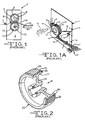
- the chopper illustrated in Figure 1 is like the chopper shown in U.S. Patent No. 3,815,461 , the disclosure of which is incorporated herein by reference.
- the choppers of Figures 1 and 1A are typical of the type of choppers suitable for use with the present invention, but other types of choppers having a blade roll with spaced apart blades that work against an elastomeric working layer of a backup roll are also usable with and in the invention. While these choppers are or will be shown pulling and chopping strands of glass fibers, these and the other suitable choppers can also be used according to the invention to pull and chop individual fibers, fiber strands of materials other than glass, wires, strings, tape(s), strip(s), ribbon(s) and similar items.
- Figures 1 and 1A show a front elevation perspective view of a portion of a prior art chopper 2, of the type shown in U.S. Pat. Nos. 3,815,461 and 4,551,160 respectively, and that are used in making chopped strand glass fiber 15.
- They each comprise a cabinet front 3, a blade roll 4 with spaced apart blades 5 contained in slots and projecting from the periphery of an integrated hub 6, a backup roll 8 and a free-wheeling idler roll 9.
- the blade roll 6, cutter roll can be made entirely of metal, with the blades separate or integral with the roll 6, but can be made using a thermoplastic material to hold spaced apart blades such as the blade rolls shown in U. S. Patent Nos.
- a backup roll 12 is held on a spindle and hub 10.
- the backup roll 12 has an elastomer working layer 13 that is biased against the blade roll 4 until the blades 5 press into the working layer 13 of the backup roll 12 a proper amount forming a nip 14 to break or separate fiber strands 1 into an array of short length or chopped strands 15.
- One or more, usually five or more and up to 14 or more strands 1, such as glass fiber strands, each strand containing 400 - 6000 or more fibers and usually having water and/or an aqueous chemical sizing on their surfaces, are pulled by the backup roll 12 into the chopper 2 and the nip 14.
- the strands 1 first run under a grooved guide roll 7, preferably with one or two strands 1 in each groove, partially around an idler roll 9 and upward and over the elastomeric working surface 13 of the backup roll 12, i.e. the exposed peripheral surface of the backup roll 12 on which the running strands 1 lay against and are supported while being severed by blades 5 on the blade roll 4.
- the working surface of the back up roll 12 is typically wider than the oscillating path of the glass fiber strands 1.
- the strands 1 then pass under the outer surface of the free-wheeling idler roll 9 located to provide sufficient contact of the strands 1 on the surface of the working layer 13 on the backup roll 12 enabling the latter to pull the glass fiber strands 1 into the chopper 2.
- the pulling speed of the pull rolls 21 is ramped up to bring the new strand 18 to at least close to the speed of the strands 1 running into the chopper 2.
- the pivot arm 20 is pivoted counterclockwise to start the new strand 18 into the chopper 2 in the manner disclosed in U.S. Pat. No. 4,551,160 .
- FIG. 2 shows a typical blade roll wheel 23 for a blade roll 4, without the blades 5.
- a portion of the blade roll 23 is cut away to better illustrate the blade roll assembly.
- the blade roll 4 is typically comprised of a hub supporting a rim 17.
- the rim 17 holds an elastomeric working layer that the chopper blades 5 work against.
- the blades 5 usually must penetrate the top surface 25 a desired distance as is well known to chop all the fibers or other items.
- the chopping blades 5 sit in slots 26 that extend part of the way through the thickness of the working layer 24, usually half way or more through the thickness of the working layer 24, and rest on the bottom of the slots 27.
- the working layer 24 can be most any elastomeric material having a hardness sufficient to hold the blades and typically is a polyurethane or rubber material.
- Figure 2A a partial perspective view of the same blade roll wheel 23 as shown in Figure 2 , has blades 5 in some or all of the slots 24 of the working layer 24 and a blade retention ring 28 held in place on the blade roll wheel 23 with bolts 30 that screw into threaded holes 31 in the rim 17 of the blade roll wheel 23.
- the blades 5 are held securely in place as the blade retention rings 28 (the blade retention ring on the backside of the backup roll 4 is not shown, but is just like the front blade retention ring 28 that is shown) with a cushion ring 29 of compressible material as shown and described in U.S. Patent No. 4,249,441 , the disclosure thereof being incorporated herein by reference.
- the cushion ring 29 is held in place with an annular bead 32 that fits into an annular groove 33 in an inner face of the blade retention ring 28.
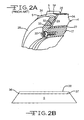
- FIG 2B shows a typical blade 5 used in the choppers shown in Figures 1, 1A and 1B .
- This is one suitable shape used, but the shape or size of the blades is not critical as many shapes and sizes can be used in various blade roll designs as is well known. In the past these blades have been made from razor blade quality stainless or carbon steel and this has been the standard for many years.
- the top edge 36 of the blade is ground to a sharp edge, starting from a short distance back from the edge at 37, normally at least a distance in the range of about 1 to about 12 mm , more typically about 2 - 7 mm, and having a tapered portion 36 ending at the sharp edge 38.
- the edge of the blades that contact the item to be separated is razor blade sharp when the blade is new.
- the worn tungsten carbide containing blades can be resharpened by grinding in a conventional manner and that the re-sharpened blades cost only about 0.33 times the original blade cost. There is a limit to how many times the W2C blades can be resharpened, but they can be sharpened at least about 5 times.
- the invention includes blades having their working portions coated with a material selected from the group consisting of metal oxides, nitrides, carbides, borides, mixtures of a metal and an oxide, nitride or carbide, tungsten carbide, titanium carbonitride, zirconium nitride, titanium aluminum nitride, chromium/boron carbide, chromium/diamond-like carbon, titanium diboride/chromium, titanium diboride/titanium carbo-nitride composite, ceramics containing binders, molybdenum, diamond, diamond-like material, silicon, silicon carbide, vanadium, tantalum, nickel, niobium, niobium/molybdenum alloys, VYDAX, PTFE, chromium, boron carbide, titanium carbide, vanadium carbide, chromium carbide, titanium nitride, chromium nitride, boron nit
- the blades made from cobalt bonded tungsten carbide, or carbon steel or stainless steel coated with, one or more of the acid-sensitive materials described or named in the previous paragraph can be protected by coatings of acid resistant materials named above to permit items having chemical sizings on their surfaces having a pH of less than 7 to be chopped without significantly detracting from the blade life achieved on sizings having a pH of greater than about 7.
- Methods of producing coatings like tungsten carbide (without cobalt as a binder), TiN, TiC, TiCN, ZrCN, CrN, diamond-like carbon films and other materials mentioned above include known techniques such as chemical vapor deposition (CVD), plasma assisted CVD, physical vapor deposition (PVD), ion beam, laser ablation, RF plasma, microwave, arc discharge, and cathodic arc plasma deposition.
- CVD chemical vapor deposition
- PVD physical vapor deposition
- ion beam laser ablation
- RF plasma RF plasma
- microwave microwave
- arc discharge and cathodic arc plasma deposition
- the coating material may be deposited on the substrate via numerous techniques including sputtering, reactive sputtering, ion beam sputtering, ion plating, electron beam gun evaporation or sublimation, electron beam gun reactive evaporation or sublimation, resistive evaporation, resistive reactive evaporation, cathodic arc evaporation or chemical vapor deposition.
Landscapes
- Engineering & Computer Science (AREA)
- Textile Engineering (AREA)
- Preliminary Treatment Of Fibers (AREA)
- Inorganic Fibers (AREA)
- Treatment Of Fiber Materials (AREA)
Priority Applications (2)
| Application Number | Priority Date | Filing Date | Title |
|---|---|---|---|
| PL08003625T PL1964950T3 (pl) | 2007-03-02 | 2008-02-28 | Sposób cięcia rozwiniętych włókien oraz powlekane ostrza maszyny tnącej |
| SI200831483T SI1964950T1 (sl) | 2007-03-02 | 2008-02-28 | Postopek za sekljanje odvitih filamentov in prevlečena rezila za sekljanje |
Applications Claiming Priority (1)
| Application Number | Priority Date | Filing Date | Title |
|---|---|---|---|
| US11/713,428 US20080210066A1 (en) | 2007-03-02 | 2007-03-02 | Method for chopping unwound items and coated chopper blades |
Publications (3)
| Publication Number | Publication Date |
|---|---|
| EP1964950A2 true EP1964950A2 (fr) | 2008-09-03 |
| EP1964950A3 EP1964950A3 (fr) | 2009-12-09 |
| EP1964950B1 EP1964950B1 (fr) | 2015-06-10 |
Family
ID=39495763
Family Applications (1)
| Application Number | Title | Priority Date | Filing Date |
|---|---|---|---|
| EP08003625.4A Active EP1964950B1 (fr) | 2007-03-02 | 2008-02-28 | Procédé de coupe de filaments déroulés et lames de coupe à surfaces traitées |
Country Status (4)
| Country | Link |
|---|---|
| US (1) | US20080210066A1 (fr) |
| EP (1) | EP1964950B1 (fr) |
| PL (1) | PL1964950T3 (fr) |
| SI (1) | SI1964950T1 (fr) |
Families Citing this family (10)
| Publication number | Priority date | Publication date | Assignee | Title |
|---|---|---|---|---|
| DE102007045383A1 (de) * | 2007-09-22 | 2008-07-17 | Bohle Ag | Verfahren zur Herstellung von Schneidrädchen |
| DE202007013307U1 (de) * | 2007-09-22 | 2008-04-24 | Bohle Ag | Schneidrädchen |
| US8951317B1 (en) * | 2009-04-27 | 2015-02-10 | Us Synthetic Corporation | Superabrasive elements including ceramic coatings and methods of leaching catalysts from superabrasive elements |
| US9352447B2 (en) * | 2009-09-08 | 2016-05-31 | Us Synthetic Corporation | Superabrasive elements and methods for processing and manufacturing the same using protective layers |
| US20120151847A1 (en) * | 2010-12-21 | 2012-06-21 | Ladi Ram L | Protective system for leaching polycrystalline diamond elements |
| JP6417227B2 (ja) | 2015-01-27 | 2018-10-31 | 株式会社ディスコ | 切削ブレード及び切削装置並びにウエーハの加工方法 |
| JP6462422B2 (ja) * | 2015-03-03 | 2019-01-30 | 株式会社ディスコ | 切削装置及びウエーハの加工方法 |
| WO2017095688A1 (fr) * | 2015-12-02 | 2017-06-08 | Ocv Intellectual Capital, Llc | Ensemble hacheur et procédé de fabrication de fibres hachées |
| EP3405440B1 (fr) | 2016-01-19 | 2020-09-09 | OCV Intellectual Capital, LLC | Hacheur de fibres et procédé de fabrication de fibres hachées |
| CN112522818A (zh) * | 2020-11-20 | 2021-03-19 | 湖南康宝源科技实业有限公司 | 一种纤维棉加工用进料装置 |
Citations (15)
| Publication number | Priority date | Publication date | Assignee | Title |
|---|---|---|---|---|
| US3508461A (en) | 1967-10-04 | 1970-04-28 | Owens Corning Fiberglass Corp | Chopper for glass strands |
| US3815461A (en) | 1972-10-26 | 1974-06-11 | Johns Manville | Apparatus for chopping strand |
| US3869268A (en) | 1973-12-11 | 1975-03-04 | Ppg Industries Inc | Method and apparatus for chopping fibers |
| US4083279A (en) | 1976-05-10 | 1978-04-11 | Johns-Manville Corporation | Apparatus for chopping strand |
| US4249441A (en) | 1979-03-09 | 1981-02-10 | Johns-Manville Corporation | Apparatus for chopping strand |
| US4287799A (en) | 1976-07-20 | 1981-09-08 | Nitto Boseki Co., Ltd. | Roller apparatus for cutting glass fibers |
| US4369681A (en) | 1980-11-19 | 1983-01-25 | Lummus Industries, Inc. | Inside-out cutter for elongated material such as tow |
| US4398934A (en) | 1978-11-24 | 1983-08-16 | Tba Industrial Products Ltd. | Manufacture of staple glass fibers |
| US4551160A (en) | 1984-10-22 | 1985-11-05 | Owens-Corning Fiberglas Corporation | Method and apparatus for forming glass filaments |
| US4569264A (en) | 1984-11-29 | 1986-02-11 | Lummus Industries, Inc. | Apparatus for cutting elongated material into shorter lengths |
| EP0305057A2 (fr) | 1987-08-28 | 1989-03-01 | Lummus Industries, Inc. | Appareil pour couper des fibres allongées |
| US5398575A (en) | 1992-02-08 | 1995-03-21 | Hoechst Aktiengesellschaft | Apparatus for continuously cutting up material in sliver or strand form |
| US5894773A (en) | 1996-08-30 | 1999-04-20 | Owens Corning Fiberglas Technology, Inc. | System for forming and cutting a mineral fiber tow |
| US5970837A (en) | 1996-12-18 | 1999-10-26 | Johns Manville International, Inc. | Chopper for cutting fiber continuously, and method |
| US6517017B1 (en) | 2001-08-07 | 2003-02-11 | Masco Corporation | End mill fiber chopper |
Family Cites Families (21)
| Publication number | Priority date | Publication date | Assignee | Title |
|---|---|---|---|---|
| US3320164A (en) * | 1965-07-14 | 1967-05-16 | Brunel Henri | Non-corrosive, lubricating, cutting and cooling additives |
| US3684470A (en) * | 1970-06-08 | 1972-08-15 | Owens Corning Fiberglass Corp | Method for treating glass fibers |
| US4043779A (en) * | 1976-03-08 | 1977-08-23 | Ppg Industries, Inc. | Apparatus for chopping coated glass fibers |
| US4626289A (en) * | 1982-09-24 | 1986-12-02 | Ppg Industries, Inc. | Treated glass fibers and aqueous dispersion and nonwoven mat of glass fibers |
| US4696352A (en) * | 1986-03-17 | 1987-09-29 | Gte Laboratories Incorporated | Insert for a drilling tool bit and a method of drilling therewith |
| US4964891A (en) * | 1988-11-13 | 1990-10-23 | Ppg Industries, Inc. | Programmably controlled fiber glass strand feeders and improved methods for making glass fiber mats |
| US4995892A (en) * | 1989-12-19 | 1991-02-26 | Ppg Industries, Inc. | Process and apparatus for controlling the thermal environment of glass fiber forming |
| US5511587A (en) * | 1990-09-28 | 1996-04-30 | Citizen Watch Co., Ltd. | Wear-resistant reed for a high-speed loom |
| US5437928A (en) * | 1993-10-29 | 1995-08-01 | Ppg Industries, Inc. | Glass fiber size and mat |
| US5824413A (en) * | 1996-07-15 | 1998-10-20 | Ppg Industries, Inc. | Secondary coating for fiber strands, coated strand reinforcements, reinforced polymeric composites and a method of reinforcing a polymeric material |
| US5804313A (en) * | 1996-07-15 | 1998-09-08 | Ppg Industries, Inc. | Polyamide and acrylic polymer coated glass fiber reinforcements, reinforced polymeric composites and a method of reinforcing a polymeric material |
| US6706670B2 (en) * | 1996-08-30 | 2004-03-16 | Solutia, Inc. | Water soluble metal working fluids |
| US5868982A (en) * | 1997-04-01 | 1999-02-09 | Owens-Corning Fiberglas Technology, Inc. | System for preparing glass fiber pellets |
| US6139955A (en) * | 1997-05-08 | 2000-10-31 | Ppg Industris Ohio, Inc. | Coated fiber strands reinforced composites and geosynthetic materials |
| DE19818046B4 (de) * | 1998-04-22 | 2004-07-08 | Johns Manville Europe Gmbh | Schlichte und Verwendung der Schlichte |
| US6228281B1 (en) * | 1998-10-30 | 2001-05-08 | Owens Corning Fiberglas Technology | Sizing for glass fibers having low nonionic and cationic lubricant content |
| US6365272B1 (en) * | 1999-12-29 | 2002-04-02 | Owens Corning Fiberglas Technology, Inc. | System for preparing glass fiber pellets having low discoloration |
| EP1306150B1 (fr) * | 2000-07-12 | 2012-03-21 | Sumitomo Electric Industries, Ltd. | Outil coupant pourvu d'un revetement |
| JP2006255822A (ja) * | 2005-03-16 | 2006-09-28 | Nippon Electric Glass Co Ltd | 繊維切断刃及びそれを具備する切断装置 |
| EP1847346A1 (fr) * | 2006-03-28 | 2007-10-24 | Precicarb | Outil de coupe en carbure et procédé de fabrication d'un tel outil |
| EP1920846A1 (fr) * | 2006-11-10 | 2008-05-14 | Precicarb SA | Contre-couteau pour outil de coupe rotatif dans un granulateur |
-
2007
- 2007-03-02 US US11/713,428 patent/US20080210066A1/en not_active Abandoned
-
2008
- 2008-02-28 EP EP08003625.4A patent/EP1964950B1/fr active Active
- 2008-02-28 PL PL08003625T patent/PL1964950T3/pl unknown
- 2008-02-28 SI SI200831483T patent/SI1964950T1/sl unknown
Patent Citations (15)
| Publication number | Priority date | Publication date | Assignee | Title |
|---|---|---|---|---|
| US3508461A (en) | 1967-10-04 | 1970-04-28 | Owens Corning Fiberglass Corp | Chopper for glass strands |
| US3815461A (en) | 1972-10-26 | 1974-06-11 | Johns Manville | Apparatus for chopping strand |
| US3869268A (en) | 1973-12-11 | 1975-03-04 | Ppg Industries Inc | Method and apparatus for chopping fibers |
| US4083279A (en) | 1976-05-10 | 1978-04-11 | Johns-Manville Corporation | Apparatus for chopping strand |
| US4287799A (en) | 1976-07-20 | 1981-09-08 | Nitto Boseki Co., Ltd. | Roller apparatus for cutting glass fibers |
| US4398934A (en) | 1978-11-24 | 1983-08-16 | Tba Industrial Products Ltd. | Manufacture of staple glass fibers |
| US4249441A (en) | 1979-03-09 | 1981-02-10 | Johns-Manville Corporation | Apparatus for chopping strand |
| US4369681A (en) | 1980-11-19 | 1983-01-25 | Lummus Industries, Inc. | Inside-out cutter for elongated material such as tow |
| US4551160A (en) | 1984-10-22 | 1985-11-05 | Owens-Corning Fiberglas Corporation | Method and apparatus for forming glass filaments |
| US4569264A (en) | 1984-11-29 | 1986-02-11 | Lummus Industries, Inc. | Apparatus for cutting elongated material into shorter lengths |
| EP0305057A2 (fr) | 1987-08-28 | 1989-03-01 | Lummus Industries, Inc. | Appareil pour couper des fibres allongées |
| US5398575A (en) | 1992-02-08 | 1995-03-21 | Hoechst Aktiengesellschaft | Apparatus for continuously cutting up material in sliver or strand form |
| US5894773A (en) | 1996-08-30 | 1999-04-20 | Owens Corning Fiberglas Technology, Inc. | System for forming and cutting a mineral fiber tow |
| US5970837A (en) | 1996-12-18 | 1999-10-26 | Johns Manville International, Inc. | Chopper for cutting fiber continuously, and method |
| US6517017B1 (en) | 2001-08-07 | 2003-02-11 | Masco Corporation | End mill fiber chopper |
Also Published As
| Publication number | Publication date |
|---|---|
| PL1964950T3 (pl) | 2015-11-30 |
| EP1964950A3 (fr) | 2009-12-09 |
| US20080210066A1 (en) | 2008-09-04 |
| SI1964950T1 (sl) | 2015-10-30 |
| EP1964950B1 (fr) | 2015-06-10 |
Similar Documents
| Publication | Publication Date | Title |
|---|---|---|
| EP1964950A2 (fr) | Procédé de coupe de filaments déroulés et lames de coupe à surfaces traitées | |
| US4653373A (en) | Knife blade and method for making same | |
| KR100543804B1 (ko) | 면도기 면도날과 그 제조방법 | |
| EP2323819B2 (fr) | Lames de rasoir | |
| EP2527492B1 (fr) | Structure de bord de coupe pour un outil de coupe, et outil de coupe comprenant la structure de bord de coupe | |
| EP1487619B1 (fr) | Outil de coupe auto-aiguisant rev tement durci | |
| EP2379262B1 (fr) | Fraise en bout pour perçage orbital | |
| US20070072008A1 (en) | Metal strip product | |
| US8904650B2 (en) | Cutting tool with blade made of fine-crystalline diamond | |
| US7871026B2 (en) | Method of chopping unwound items | |
| US7938155B2 (en) | Ring strander knife assembly and method of use | |
| WO1999054520A1 (fr) | Parties d'une machine a papier/carton ou de finissage soumises a une usure intensive, et procede de fabrication de telles parties | |
| JPH11502449A (ja) | ナイフの刃 | |
| EP3031982B1 (fr) | Lame de crêpage revêtue de cermet à durée de vie longue | |
| US3890706A (en) | Roving cutter for fiber reinforced synthetic resin sprayers | |
| WO2007061004A1 (fr) | Tronçonneuse de cordon de fibre de verre | |
| US6527211B1 (en) | Blade and spring fiber chopper | |
| CN210819745U (zh) | 一种玻璃纤维毡纵向分切装置 | |
| JP4639852B2 (ja) | ロータリーダイカッター | |
| JP2001269896A (ja) | ダイカットロールおよびそれを用いる裁断装置 | |
| CN108687976B (zh) | 一种石材切割刀具 | |
| US8573103B2 (en) | Fiber chopper | |
| JP2000177032A (ja) | 加工用ロール | |
| JP4771693B2 (ja) | ガラス繊維ストランドの切断装置 | |
| JPH1142590A (ja) | ナイフおよびそれを用いた切断方法 |
Legal Events
| Date | Code | Title | Description |
|---|---|---|---|
| PUAI | Public reference made under article 153(3) epc to a published international application that has entered the european phase |
Free format text: ORIGINAL CODE: 0009012 |
|
| AK | Designated contracting states |
Kind code of ref document: A2 Designated state(s): AT BE BG CH CY CZ DE DK EE ES FI FR GB GR HR HU IE IS IT LI LT LU LV MC MT NL NO PL PT RO SE SI SK TR |
|
| AX | Request for extension of the european patent |
Extension state: AL BA MK RS |
|
| PUAL | Search report despatched |
Free format text: ORIGINAL CODE: 0009013 |
|
| AK | Designated contracting states |
Kind code of ref document: A3 Designated state(s): AT BE BG CH CY CZ DE DK EE ES FI FR GB GR HR HU IE IS IT LI LT LU LV MC MT NL NO PL PT RO SE SI SK TR |
|
| AX | Request for extension of the european patent |
Extension state: AL BA MK RS |
|
| 17P | Request for examination filed |
Effective date: 20100528 |
|
| AKX | Designation fees paid |
Designated state(s): AT BE BG CH CY CZ DE DK EE ES FI FR GB GR HR HU IE IS IT LI LT LU LV MC MT NL NO PL PT RO SE SI SK TR |
|
| 17Q | First examination report despatched |
Effective date: 20110912 |
|
| GRAP | Despatch of communication of intention to grant a patent |
Free format text: ORIGINAL CODE: EPIDOSNIGR1 |
|
| INTG | Intention to grant announced |
Effective date: 20150109 |
|
| GRAS | Grant fee paid |
Free format text: ORIGINAL CODE: EPIDOSNIGR3 |
|
| GRAA | (expected) grant |
Free format text: ORIGINAL CODE: 0009210 |
|
| AK | Designated contracting states |
Kind code of ref document: B1 Designated state(s): AT BE BG CH CY CZ DE DK EE ES FI FR GB GR HR HU IE IS IT LI LT LU LV MC MT NL NO PL PT RO SE SI SK TR |
|
| REG | Reference to a national code |
Ref country code: GB Ref legal event code: FG4D |
|
| REG | Reference to a national code |
Ref country code: CH Ref legal event code: EP |
|
| REG | Reference to a national code |
Ref country code: AT Ref legal event code: REF Ref document number: 730950 Country of ref document: AT Kind code of ref document: T Effective date: 20150715 |
|
| REG | Reference to a national code |
Ref country code: DE Ref legal event code: R096 Ref document number: 602008038479 Country of ref document: DE |
|
| REG | Reference to a national code |
Ref country code: IE Ref legal event code: FG4D |
|
| REG | Reference to a national code |
Ref country code: NL Ref legal event code: T3 |
|
| PG25 | Lapsed in a contracting state [announced via postgrant information from national office to epo] |
Ref country code: NO Free format text: LAPSE BECAUSE OF FAILURE TO SUBMIT A TRANSLATION OF THE DESCRIPTION OR TO PAY THE FEE WITHIN THE PRESCRIBED TIME-LIMIT Effective date: 20150910 Ref country code: LT Free format text: LAPSE BECAUSE OF FAILURE TO SUBMIT A TRANSLATION OF THE DESCRIPTION OR TO PAY THE FEE WITHIN THE PRESCRIBED TIME-LIMIT Effective date: 20150610 Ref country code: ES Free format text: LAPSE BECAUSE OF FAILURE TO SUBMIT A TRANSLATION OF THE DESCRIPTION OR TO PAY THE FEE WITHIN THE PRESCRIBED TIME-LIMIT Effective date: 20150610 |
|
| REG | Reference to a national code |
Ref country code: SK Ref legal event code: T3 Ref document number: E 19088 Country of ref document: SK |
|
| REG | Reference to a national code |
Ref country code: AT Ref legal event code: MK05 Ref document number: 730950 Country of ref document: AT Kind code of ref document: T Effective date: 20150610 |
|
| PG25 | Lapsed in a contracting state [announced via postgrant information from national office to epo] |
Ref country code: BG Free format text: LAPSE BECAUSE OF FAILURE TO SUBMIT A TRANSLATION OF THE DESCRIPTION OR TO PAY THE FEE WITHIN THE PRESCRIBED TIME-LIMIT Effective date: 20150910 Ref country code: GR Free format text: LAPSE BECAUSE OF FAILURE TO SUBMIT A TRANSLATION OF THE DESCRIPTION OR TO PAY THE FEE WITHIN THE PRESCRIBED TIME-LIMIT Effective date: 20150911 Ref country code: LV Free format text: LAPSE BECAUSE OF FAILURE TO SUBMIT A TRANSLATION OF THE DESCRIPTION OR TO PAY THE FEE WITHIN THE PRESCRIBED TIME-LIMIT Effective date: 20150610 |
|
| REG | Reference to a national code |
Ref country code: PL Ref legal event code: T3 |
|
| PG25 | Lapsed in a contracting state [announced via postgrant information from national office to epo] |
Ref country code: EE Free format text: LAPSE BECAUSE OF FAILURE TO SUBMIT A TRANSLATION OF THE DESCRIPTION OR TO PAY THE FEE WITHIN THE PRESCRIBED TIME-LIMIT Effective date: 20150610 |
|
| REG | Reference to a national code |
Ref country code: FR Ref legal event code: PLFP Year of fee payment: 9 |
|
| PG25 | Lapsed in a contracting state [announced via postgrant information from national office to epo] |
Ref country code: RO Free format text: LAPSE BECAUSE OF NON-PAYMENT OF DUE FEES Effective date: 20150610 Ref country code: IS Free format text: LAPSE BECAUSE OF FAILURE TO SUBMIT A TRANSLATION OF THE DESCRIPTION OR TO PAY THE FEE WITHIN THE PRESCRIBED TIME-LIMIT Effective date: 20151010 Ref country code: AT Free format text: LAPSE BECAUSE OF FAILURE TO SUBMIT A TRANSLATION OF THE DESCRIPTION OR TO PAY THE FEE WITHIN THE PRESCRIBED TIME-LIMIT Effective date: 20150610 Ref country code: PT Free format text: LAPSE BECAUSE OF FAILURE TO SUBMIT A TRANSLATION OF THE DESCRIPTION OR TO PAY THE FEE WITHIN THE PRESCRIBED TIME-LIMIT Effective date: 20151012 |
|
| REG | Reference to a national code |
Ref country code: DE Ref legal event code: R097 Ref document number: 602008038479 Country of ref document: DE |
|
| PLBE | No opposition filed within time limit |
Free format text: ORIGINAL CODE: 0009261 |
|
| STAA | Information on the status of an ep patent application or granted ep patent |
Free format text: STATUS: NO OPPOSITION FILED WITHIN TIME LIMIT |
|
| PG25 | Lapsed in a contracting state [announced via postgrant information from national office to epo] |
Ref country code: DK Free format text: LAPSE BECAUSE OF FAILURE TO SUBMIT A TRANSLATION OF THE DESCRIPTION OR TO PAY THE FEE WITHIN THE PRESCRIBED TIME-LIMIT Effective date: 20150610 Ref country code: IT Free format text: LAPSE BECAUSE OF FAILURE TO SUBMIT A TRANSLATION OF THE DESCRIPTION OR TO PAY THE FEE WITHIN THE PRESCRIBED TIME-LIMIT Effective date: 20150610 |
|
| 26N | No opposition filed |
Effective date: 20160311 |
|
| PG25 | Lapsed in a contracting state [announced via postgrant information from national office to epo] |
Ref country code: LU Free format text: LAPSE BECAUSE OF FAILURE TO SUBMIT A TRANSLATION OF THE DESCRIPTION OR TO PAY THE FEE WITHIN THE PRESCRIBED TIME-LIMIT Effective date: 20160228 Ref country code: MC Free format text: LAPSE BECAUSE OF FAILURE TO SUBMIT A TRANSLATION OF THE DESCRIPTION OR TO PAY THE FEE WITHIN THE PRESCRIBED TIME-LIMIT Effective date: 20150610 |
|
| REG | Reference to a national code |
Ref country code: CH Ref legal event code: PL |
|
| GBPC | Gb: european patent ceased through non-payment of renewal fee |
Effective date: 20160228 |
|
| PG25 | Lapsed in a contracting state [announced via postgrant information from national office to epo] |
Ref country code: LI Free format text: LAPSE BECAUSE OF NON-PAYMENT OF DUE FEES Effective date: 20160229 Ref country code: CH Free format text: LAPSE BECAUSE OF NON-PAYMENT OF DUE FEES Effective date: 20160229 |
|
| REG | Reference to a national code |
Ref country code: IE Ref legal event code: MM4A |
|
| PG25 | Lapsed in a contracting state [announced via postgrant information from national office to epo] |
Ref country code: IE Free format text: LAPSE BECAUSE OF NON-PAYMENT OF DUE FEES Effective date: 20160228 Ref country code: GB Free format text: LAPSE BECAUSE OF NON-PAYMENT OF DUE FEES Effective date: 20160228 |
|
| REG | Reference to a national code |
Ref country code: FR Ref legal event code: PLFP Year of fee payment: 10 |
|
| PG25 | Lapsed in a contracting state [announced via postgrant information from national office to epo] |
Ref country code: SE Free format text: LAPSE BECAUSE OF FAILURE TO SUBMIT A TRANSLATION OF THE DESCRIPTION OR TO PAY THE FEE WITHIN THE PRESCRIBED TIME-LIMIT Effective date: 20150610 |
|
| PG25 | Lapsed in a contracting state [announced via postgrant information from national office to epo] |
Ref country code: MT Free format text: LAPSE BECAUSE OF FAILURE TO SUBMIT A TRANSLATION OF THE DESCRIPTION OR TO PAY THE FEE WITHIN THE PRESCRIBED TIME-LIMIT Effective date: 20150610 |
|
| REG | Reference to a national code |
Ref country code: FR Ref legal event code: PLFP Year of fee payment: 11 |
|
| PG25 | Lapsed in a contracting state [announced via postgrant information from national office to epo] |
Ref country code: CY Free format text: LAPSE BECAUSE OF FAILURE TO SUBMIT A TRANSLATION OF THE DESCRIPTION OR TO PAY THE FEE WITHIN THE PRESCRIBED TIME-LIMIT Effective date: 20150610 Ref country code: HU Free format text: LAPSE BECAUSE OF FAILURE TO SUBMIT A TRANSLATION OF THE DESCRIPTION OR TO PAY THE FEE WITHIN THE PRESCRIBED TIME-LIMIT; INVALID AB INITIO Effective date: 20080228 |
|
| PG25 | Lapsed in a contracting state [announced via postgrant information from national office to epo] |
Ref country code: HR Free format text: LAPSE BECAUSE OF FAILURE TO SUBMIT A TRANSLATION OF THE DESCRIPTION OR TO PAY THE FEE WITHIN THE PRESCRIBED TIME-LIMIT Effective date: 20150610 Ref country code: MT Free format text: LAPSE BECAUSE OF FAILURE TO SUBMIT A TRANSLATION OF THE DESCRIPTION OR TO PAY THE FEE WITHIN THE PRESCRIBED TIME-LIMIT Effective date: 20160229 |
|
| REG | Reference to a national code |
Ref country code: DE Ref legal event code: R082 Ref document number: 602008038479 Country of ref document: DE |
|
| PGFP | Annual fee paid to national office [announced via postgrant information from national office to epo] |
Ref country code: NL Payment date: 20240226 Year of fee payment: 17 |
|
| PGFP | Annual fee paid to national office [announced via postgrant information from national office to epo] |
Ref country code: FI Payment date: 20240226 Year of fee payment: 17 Ref country code: DE Payment date: 20240228 Year of fee payment: 17 Ref country code: CZ Payment date: 20240207 Year of fee payment: 17 Ref country code: SK Payment date: 20240131 Year of fee payment: 17 |
|
| PGFP | Annual fee paid to national office [announced via postgrant information from national office to epo] |
Ref country code: SI Payment date: 20240201 Year of fee payment: 17 |
|
| PGFP | Annual fee paid to national office [announced via postgrant information from national office to epo] |
Ref country code: TR Payment date: 20240214 Year of fee payment: 17 Ref country code: PL Payment date: 20240201 Year of fee payment: 17 Ref country code: FR Payment date: 20240226 Year of fee payment: 17 Ref country code: BE Payment date: 20240227 Year of fee payment: 17 |