EP1963559B1 - Befestigungsvorrichtung für einen motor in einem haushaltgerät - Google Patents
Befestigungsvorrichtung für einen motor in einem haushaltgerät Download PDFInfo
- Publication number
- EP1963559B1 EP1963559B1 EP06830184A EP06830184A EP1963559B1 EP 1963559 B1 EP1963559 B1 EP 1963559B1 EP 06830184 A EP06830184 A EP 06830184A EP 06830184 A EP06830184 A EP 06830184A EP 1963559 B1 EP1963559 B1 EP 1963559B1
- Authority
- EP
- European Patent Office
- Prior art keywords
- region
- fastening device
- motor
- securing element
- securing
- Prior art date
- Legal status (The legal status is an assumption and is not a legal conclusion. Google has not performed a legal analysis and makes no representation as to the accuracy of the status listed.)
- Not-in-force
Links
- 238000003780 insertion Methods 0.000 claims description 13
- 230000037431 insertion Effects 0.000 claims description 13
- 230000000903 blocking effect Effects 0.000 claims description 12
- 238000010412 laundry washing Methods 0.000 claims description 3
- 238000005406 washing Methods 0.000 description 10
- 101150114468 TUB1 gene Proteins 0.000 description 7
- 230000005540 biological transmission Effects 0.000 description 5
- 239000000725 suspension Substances 0.000 description 5
- 239000002184 metal Substances 0.000 description 3
- 238000011161 development Methods 0.000 description 2
- 230000018109 developmental process Effects 0.000 description 2
- 238000004519 manufacturing process Methods 0.000 description 2
- 241000587161 Gomphocarpus Species 0.000 description 1
- 238000006073 displacement reaction Methods 0.000 description 1
- 230000000694 effects Effects 0.000 description 1
- 238000002347 injection Methods 0.000 description 1
- 239000007924 injection Substances 0.000 description 1
- 238000012423 maintenance Methods 0.000 description 1
- 230000002093 peripheral effect Effects 0.000 description 1
Images


Classifications
-
- D—TEXTILES; PAPER
- D06—TREATMENT OF TEXTILES OR THE LIKE; LAUNDERING; FLEXIBLE MATERIALS NOT OTHERWISE PROVIDED FOR
- D06F—LAUNDERING, DRYING, IRONING, PRESSING OR FOLDING TEXTILE ARTICLES
- D06F37/00—Details specific to washing machines covered by groups D06F21/00 - D06F25/00
- D06F37/20—Mountings, e.g. resilient mountings, for the rotary receptacle, motor, tub or casing; Preventing or damping vibrations
- D06F37/206—Mounting of motor
-
- D—TEXTILES; PAPER
- D06—TREATMENT OF TEXTILES OR THE LIKE; LAUNDERING; FLEXIBLE MATERIALS NOT OTHERWISE PROVIDED FOR
- D06F—LAUNDERING, DRYING, IRONING, PRESSING OR FOLDING TEXTILE ARTICLES
- D06F37/00—Details specific to washing machines covered by groups D06F21/00 - D06F25/00
- D06F37/30—Driving arrangements
- D06F37/40—Driving arrangements for driving the receptacle and an agitator or impeller, e.g. alternatively
-
- D—TEXTILES; PAPER
- D06—TREATMENT OF TEXTILES OR THE LIKE; LAUNDERING; FLEXIBLE MATERIALS NOT OTHERWISE PROVIDED FOR
- D06F—LAUNDERING, DRYING, IRONING, PRESSING OR FOLDING TEXTILE ARTICLES
- D06F58/00—Domestic laundry dryers
- D06F58/02—Domestic laundry dryers having dryer drums rotating about a horizontal axis
- D06F58/04—Details
- D06F58/08—Driving arrangements
-
- F—MECHANICAL ENGINEERING; LIGHTING; HEATING; WEAPONS; BLASTING
- F16—ENGINEERING ELEMENTS AND UNITS; GENERAL MEASURES FOR PRODUCING AND MAINTAINING EFFECTIVE FUNCTIONING OF MACHINES OR INSTALLATIONS; THERMAL INSULATION IN GENERAL
- F16B—DEVICES FOR FASTENING OR SECURING CONSTRUCTIONAL ELEMENTS OR MACHINE PARTS TOGETHER, e.g. NAILS, BOLTS, CIRCLIPS, CLAMPS, CLIPS OR WEDGES; JOINTS OR JOINTING
- F16B21/00—Means for preventing relative axial movement of a pin, spigot, shaft or the like and a member surrounding it; Stud-and-socket releasable fastenings
- F16B21/06—Releasable fastening devices with snap-action
-
- H—ELECTRICITY
- H02—GENERATION; CONVERSION OR DISTRIBUTION OF ELECTRIC POWER
- H02K—DYNAMO-ELECTRIC MACHINES
- H02K5/00—Casings; Enclosures; Supports
- H02K5/04—Casings or enclosures characterised by the shape, form or construction thereof
- H02K5/22—Auxiliary parts of casings not covered by groups H02K5/06-H02K5/20, e.g. shaped to form connection boxes or terminal boxes
-
- Y—GENERAL TAGGING OF NEW TECHNOLOGICAL DEVELOPMENTS; GENERAL TAGGING OF CROSS-SECTIONAL TECHNOLOGIES SPANNING OVER SEVERAL SECTIONS OF THE IPC; TECHNICAL SUBJECTS COVERED BY FORMER USPC CROSS-REFERENCE ART COLLECTIONS [XRACs] AND DIGESTS
- Y02—TECHNOLOGIES OR APPLICATIONS FOR MITIGATION OR ADAPTATION AGAINST CLIMATE CHANGE
- Y02B—CLIMATE CHANGE MITIGATION TECHNOLOGIES RELATED TO BUILDINGS, e.g. HOUSING, HOUSE APPLIANCES OR RELATED END-USER APPLICATIONS
- Y02B40/00—Technologies aiming at improving the efficiency of home appliances, e.g. induction cooking or efficient technologies for refrigerators, freezers or dish washers
Definitions
- the invention relates to a fastening device for an engine in a household appliance for the care of laundry items, in particular in a laundry washing machine or in a tumble dryer.
- Fastening devices or mounting units for motors in washing machines are known.
- a mounting unit for an electric motor described in a washing machine which is designed as a two-point motor mounting device.
- the location of the engine relative to a transmission, and particularly with respect to the belt is of central importance in order to ensure optimum operation and transmission of the engine generated power through the belt.
- the motor must therefore be positioned in an optimum position, in particular with regard to the belt.
- the known from the prior art motor is mounted on a mounting plate and supported by means of two eyelets.
- the eyelets are secured to the mounting plate by screws and nuts attached thereto.
- the plastic tub of the washing machine in one embodiment, has two projections into which a pair of annular projections of the body of the motor can be arranged with respect thereto so as to leave a peripheral free space there between, in which plastic bushes can be placed.
- the engine is in a floating position by means of his attached two annular projections.
- a screw is screwed into the plastic bushing to secure the engine to the tub.
- Another attachment device for a motor in a household appliance for the care of laundry is off DE 87 06 050 U1 known.
- the motor has at least two connection areas for the mechanical connection to a holding area formed on the household appliance.
- the mechanical connection between a connection region and the holding region is secured by a latching element.
- a fastening device for a motor in a domestic appliance for the care of laundry items is designed such that the motor has at least two connecting regions and each of these connecting regions is designed for mechanical connection to a holding region of the household appliance. At least one mechanical connection is secured between a connection region and a holding region by a latching element.
- An essential idea of the invention is that the securing of the connection between the motor and the holding area can be done exclusively with the locking element. Thereby, a fastening device can be created, which can be easily implemented and low-maintenance allows attachment of the engine. In addition, the assembly time can be reduced since it is no longer necessary to screw in or unscrew the screws used in the prior art.
- the fastening device comprises a securing element, which is designed as a pin-like male member with which the locking element is integrally connected.
- a securing element which is designed as a pin-like male member with which the locking element is integrally connected.
- the pin-like male element is positioned locked in its final position. Since the pin-like male member is formed with the locking element, the male member can be easily and reliably inserted as a securing element between the connecting portion and a holding portion and fixed position stable in its final position.
- the fastening device comprises at least one pin-like carrier element which is connected to a holding region and which is connected in one piece with the catch element to form a securing element.
- the locking element can be produced together with the carrier element and optionally with the holding device in a manufacturing step, for example by the parts are hosed together in a plastic injection mold.
- connection region of the motor is positioned locked in its end position.
- the engine can be held positionally stable in its position.
- the further developments mentioned below can be applied to a securing element in the form of the pin-like male element or the pin-like carrier element with the same effect.
- the securing element preferably has a first end region, which is at least conical.
- This first end region is preferably that end region with which the securing element is first introduced for forming the mechanical connection between the connection region and the holding region.
- the securing element is thus inserted with this first end region ahead or the connection region on this first end region of the securing element attached. Due to the conical configuration, the insertion or the insertion can be facilitated.
- the first end region at the end adjacent to a central region of the securing element is made wider than the central region.
- the first end region preferably has an at least partially encircling web at the end adjoining this middle region.
- the securing element is advantageously slotted, at least in the region of the first end region. It can thereby be achieved that the securing element in the first end region is formed quasi two-part and these two parts of the Sich ceremoniesselemnts can be moved relative to each other.
- the insertion of the connecting region onto the carrier element or the insertion or insertion of the male element for forming a mechanical connection between the connecting region and the holding region can be simplified and carried out with little effort and, on the other hand, ensures a secure locking of the connecting element or of the male element in the end position become.
- the first end region of the securing element is slotted several times and thus the securing element in the region of the first end region has a plurality of sub-elements, which are all movable relative to each other.
- the securing element is hollow at least over a length between a second end region and the slotted region.
- the second end region is arranged at the end of the central region opposite the first end region.
- a blocking element can be inserted in the hollow channel of the securing element.
- This blocking element can be designed as a securing pin and is preferably designed to be longer than the securing element.
- each holding region has at least one carrier element, in particular fastening pin, wherein the connecting regions of the motor are designed such that they can be pushed onto the carrier elements.
- the engine can be very reliably positioned in an optimal position with respect to a belt connected to the engine.
- the motor is arranged in its installed position in a suspension position.
- This suspension position or as a floating position to be designated mounting position allows a reduced component arranging and mounting the motor.
- a separate mounting plate is no longer required.
- Alone the mechanical. Connection between the connection areas and the holding areas allow reliable mounting of the motor.
- the securing element and / or the blocking element may be formed entirely from plastic or entirely from metal. However, it can also be provided that at least one of these two elements is at least partially made of plastic or at least partially of metal.
- Fig. 1 an exploded view of a section of a household appliance for the care of laundry is shown.
- this household appliance is designed as a washing machine.
- the household appliance is designed for example as a tumble dryer.
- a tub 1 is formed with a fastening device, which is designed for attachment of a motor 2 on or in the washing machine.
- the motor 2 is attached to any other support device in the washing machine by means of the fastening device.
- the motor 2 in the exemplary embodiment connecting regions 21 a, 21 b, 22 a and 22 b.
- the fastening device has in the exemplary embodiment holding areas 11a, 11b, 12a and 12b.
- the holding areas 11a, 11b, 12a and 12b in the exemplary embodiment, the carrier elements shown 41a, 41b, 42a, 42b, which may be formed, for example, as a mounting pin.
- four holding and connecting portions are shown, in alternative embodiments, the motor 2 and the fastening device may have a different number of holding and connecting portions.
- at least two connection regions are provided on the motor 2.
- the connecting portions 21 a, 21 b, 22 a and 22 b of the motor 2 are formed such that the motor 2 with these connecting portions 21 a, 21 b, 22 a and 22 b can be mechanically connected to the holding portions 11 a, 11 b, 12 a and 12 b.
- the connecting regions 21a, 21b, 22a and 22b are pushed onto the carrier elements 41a, 41b, 42a and 42b of the holding regions 11a, 11b, 12a and 12b.
- the fastening device comprises in a first in FIG. 4 illustrated embodiment, at least one locking element 31, with the at least one mechanical connection between a connecting portion and the respective holding portion, in the illustrated embodiment between the connecting portion 21 a and the holding portion 11 a, is secured by the locking element 31.
- at least one in the FIGS. 2, 3 and 4 illustrated fuse element 3 is provided, which is formed as a pin-like male member and which is integrally connected to the locking element 31.
- the securing element 3 is arranged in the region of the mechanical connection between a holding region, for example 11a, and the connecting region 21a assigned to this holding region.
- the fuse element 3 is inserted into the illustrated insertion opening 23.
- the other connection regions 11b, 12a and 12b can also be mechanically connected to the respective holding regions 21b, 22a and 22b.
- the fuse element 3 is inserted or inserted in such a way that it engages in an end position not shown in FIG and thus can not solve independently.
- the mechanical connection between the regions 11a and 21a or the mechanical connections between the regions 11b, 12a, 12b and 21b, 22a, 22b, if several securing elements 3 are included, can be fixed by the securing elements 3 thus in a simpler and more reliable manner.
- a so-called four-point connection between the engine 2 and the tub 1 is used in the embodiment.
- the holding and connecting areas can be designed such that only a two-point connection between the motor 2 and the tub 1 for attachment of the motor 2 is sufficient.
- the motor 2 is arranged in the embodiment in its installed position in a suspension position.
- the suspension position or the suspension points are formed by the mechanical connections between the respective associated holding and connecting regions, for example, 11 a and 21 a and 11 b and 21 b, etc. ,.
- the engine 2 is arranged quasi free-floating.
- the motor 2 is coupled to a belt 5, which may be provided for example to drive a transmission or a drum or even other elements of the washing machine.
- the motor 2 can be positioned so that it is arranged in an optimal position with respect to the operation of the belt 5.
- the belt 5 can thus circulate wear and allow the best possible transmission of the force generated by the engine.
- Fig. 2 is a sectional view of the fuse element 3 is shown.
- the securing element 3 has a first end region 31, a central region 32 adjoining the first end region 31 and a second end region 33 adjoining it.
- the first securing element 3 has a pin-like shape.
- the first end portion 31 is conically formed at its end 31 a facing away from the central region 32.
- the conical region 31a merges into a frustoconical region, which in the exemplary embodiment is designed as a partially circumferential web 31b.
- the web 31b is formed wider than the central region 32. Due to these different dimensions can be formed by the web 31b quasi a detent or latch lugs, which allow a locking of the first securing element 3 in the final position.
- the latching lug or latching lugs form the latching element 31 in the first end region 31 of the securing element 3.
- the first end portion 31 and the locking element 31 have the same longitudinal extent, so they are referred to by the same index. However, the first end portion and the locking element can also have different longitudinal extensions.
- the fuse element 3 is formed slotted at least in the first end portion 31.
- the slotted region 31 c protrudes partially in the middle region 32 in the embodiment shown.
- at least the first end region 31 and a part of the central region 32 are separated from one another, so that a division of at least the first end region 31 occurs through the slotted region 31c.
- the second end portion 33 is formed according to a nail head.
- Fig. 3 is a further sectional view of a fuse element 3 is shown.
- the securing element 3 in contrast to the illustration in FIG Fig. 2 a hollow channel 34 which is formed in the central region 32 and in the second end region 33.
- the hollow channel 34 and the bore extends to the slotted portion 31 c.
- a blocking element 35 is partially inserted into this hollow channel 34.
- the blocking element 35 has a length which is greater than the length of the securing element 3.
- the blocking element 35 is designed as a securing pin in the exemplary embodiment and extends in the fully inserted state from the outermost end of the first end region. 31 (in Fig. 3 left edge) to beyond the second end 33 addition.
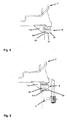
- FIGS. 5 and 6 another embodiment of the invention is shown.
- the figures show a section through the tub 1 a washing machine to a holding portion 11 a, to which a pin-like support member 62 is connected.
- the locking element 61 which is formed in the same manner as the locking element 31 of the pin-like male member 3, integrally connected.
- the carrier element 62 forms with the latching element 61 a securing element 6 onto which the connecting element 21a can be plugged or pushed.
- the connecting element 21a, and thus also the motor 2 connected to the connecting element 21a, are connected to the thus formed securing element 6 in its in Fig. 6 Positioning shown locked position.
- the carrier element 62 and the latching element 61 can be produced together with the tub 1 as a component.
- the components are advantageously carried out in plastic. Thus, no further elements are required to secure the motor 2 to the tub 1.
- the securing element 6, which consists of the locking element 61 and the support member 62, and / or the holding portion 11a made of metal, wherein in such an embodiment, the securing element 6, for example, connected to the holding portion 11a via a screw, latching or welded connection is.
- FIGS. 5 and 6 only one holding area 11a is shown, which is connected to a securing element 6.
- a securing element 6 can also be provided for a plurality of holding areas or each holding area.
- This first end region 61 is wider at an end adjacent to a central region 62 of the securing element 6 and has an at least partially circumferential web. This web is formed analogously to the web 31b of the securing element 3.
- the securing element 6 at least in the region of the first end region having a slot, not shown.
- the slotted area may also protrude partially into the central area 62.
- at least the first end region 61 and a part of the middle region 62 are separated from one another, so that a division into at least the first end region 61 is effected by the slotted region.
- a blocking element can be inserted into a hollow channel 64, which is formed at least in the middle region 62 and in the second end region 63.
- the hollow channel 64 or the bore extends to the slotted area.
- the blocking element has a length which is greater than the length of the securing element 6.
- the blocking element as in the exemplary embodiment of the securing element 3, is designed as a securing pin and extends from the outermost end of the first end region 61 beyond the second end region 63.
- the holding portions (11a, 11b, 12a, 12b) are arranged on a tub 1 a laundry washing machine.
- the invention is not limited to such an arrangement.
- the holding areas can also be arranged on other components of the household appliance, for example on a load-bearing housing component of a tumble dryer.
Landscapes
- Engineering & Computer Science (AREA)
- Textile Engineering (AREA)
- General Engineering & Computer Science (AREA)
- Mechanical Engineering (AREA)
- Power Engineering (AREA)
- Main Body Construction Of Washing Machines And Laundry Dryers (AREA)
- Connection Of Plates (AREA)
- Snaps, Bayonet Connections, Set Pins, And Snap Rings (AREA)
Priority Applications (1)
| Application Number | Priority Date | Filing Date | Title |
|---|---|---|---|
| PL06830184T PL1963559T3 (pl) | 2005-12-16 | 2006-11-29 | Urządzenie mocujące dla silnika w sprzęcie gospodarstwa domowego |
Applications Claiming Priority (2)
| Application Number | Priority Date | Filing Date | Title |
|---|---|---|---|
| DE102005060362A DE102005060362A1 (de) | 2005-12-16 | 2005-12-16 | Befestigungsvorrichtung für einen Motor in einem Haushaltgerät |
| PCT/EP2006/069042 WO2007068589A1 (de) | 2005-12-16 | 2006-11-29 | Befestigungsvorrichtung für einen motor in einem haushaltgerät |
Publications (2)
| Publication Number | Publication Date |
|---|---|
| EP1963559A1 EP1963559A1 (de) | 2008-09-03 |
| EP1963559B1 true EP1963559B1 (de) | 2013-01-09 |
Family
ID=37772823
Family Applications (1)
| Application Number | Title | Priority Date | Filing Date |
|---|---|---|---|
| EP06830184A Not-in-force EP1963559B1 (de) | 2005-12-16 | 2006-11-29 | Befestigungsvorrichtung für einen motor in einem haushaltgerät |
Country Status (8)
| Country | Link |
|---|---|
| US (1) | US20090051237A1 (pl) |
| EP (1) | EP1963559B1 (pl) |
| KR (1) | KR20080083663A (pl) |
| CN (1) | CN101331259B (pl) |
| DE (1) | DE102005060362A1 (pl) |
| EA (1) | EA013319B1 (pl) |
| PL (1) | PL1963559T3 (pl) |
| WO (1) | WO2007068589A1 (pl) |
Families Citing this family (8)
| Publication number | Priority date | Publication date | Assignee | Title |
|---|---|---|---|---|
| ES2336871B1 (es) * | 2007-09-28 | 2011-02-16 | Bsh Electrodomesticos España S.A. | Lavadora. |
| DE102011005315A1 (de) * | 2011-03-09 | 2012-09-13 | BSH Bosch und Siemens Hausgeräte GmbH | Anordnung aus einem Laugenbehälter einer Haushaltwaschmaschine und einem Antriebsmotor |
| ITPN20130015U1 (it) | 2013-03-07 | 2014-09-08 | Nidec Sole Motor Corp S R L | Apparato per il fissaggio di un motore alla vasca di una macchina lavatrice |
| CN106702675A (zh) * | 2015-07-31 | 2017-05-24 | 青岛海尔滚筒洗衣机有限公司 | 一种滚筒洗衣机电机安装装置 |
| EP3165664B1 (en) * | 2015-11-05 | 2020-07-22 | Electrolux Appliances Aktiebolag | Washing group for laundry washing machines |
| US11703179B2 (en) * | 2020-10-30 | 2023-07-18 | Hanon Systems | Bracket for aligning a compressor to an engine |
| CN112713698A (zh) * | 2020-12-29 | 2021-04-27 | 蓓慈电器有限公司 | 一种旋转式固定电机组件及足浴器 |
| KR20240085036A (ko) * | 2022-12-07 | 2024-06-14 | 삼성전자주식회사 | 모터 고정 구조체 및 이를 포함하는 세탁기 |
Family Cites Families (36)
| Publication number | Priority date | Publication date | Assignee | Title |
|---|---|---|---|---|
| DE7738479U1 (pl) * | 1900-01-01 | Bosch-Siemens Hausgeraete Gmbh, 7000 Stuttgart | ||
| US362548A (en) * | 1887-05-10 | Obeblin smith | ||
| US919925A (en) * | 1909-03-13 | 1909-04-27 | Mcwhorter Mfg Company | Cotter-key. |
| US1688119A (en) * | 1926-06-01 | 1928-10-16 | Modern Laundry Machine Mfg Com | Motor support for washing machines |
| US2136787A (en) * | 1928-09-25 | 1938-11-15 | Winchester Repeating Arms Co | Washing machine |
| US1913378A (en) * | 1928-09-25 | 1933-06-13 | Whirldry Corp | Laundry apparatus |
| US1815190A (en) * | 1928-12-03 | 1931-07-21 | Bush Ag | Driving mechanism for combined washers and driers |
| US1957770A (en) * | 1932-07-08 | 1934-05-08 | American Rolling Mill Co | Fastening device |
| US2058338A (en) * | 1934-06-01 | 1936-10-20 | William E Meissner | Hollow rivet |
| US2086931A (en) * | 1934-12-01 | 1937-07-13 | Thomas W Behan | Speed reduction and motion translating mechanism |
| US2109576A (en) * | 1935-04-06 | 1938-03-01 | George E Gagnier | Fastener |
| US2275189A (en) * | 1939-04-22 | 1942-03-03 | Albert O Wieghart | Dishwashing machine |
| US2360278A (en) * | 1942-03-25 | 1944-10-10 | Westinghouse Electric & Mfg Co | Apparatus for cleaning fabrics |
| US2699849A (en) * | 1952-06-13 | 1955-01-18 | Solar Corp | Drive for washing machines |
| US4037513A (en) * | 1976-09-03 | 1977-07-26 | Portec, Inc. | Cotter pin |
| US4662808A (en) * | 1985-10-02 | 1987-05-05 | Lee-Rowan Company | Wall anchor |
| IT211132Z2 (it) * | 1986-05-08 | 1989-02-13 | Zanussi Elettromecc | Dispositivo per il fissaggio del motore di una macchine asciugabiancheria. |
| US4830556A (en) * | 1987-07-01 | 1989-05-16 | Illinois Tool Works Inc. | Plastic rivet having flexible drive pin |
| US4922151A (en) * | 1988-08-02 | 1990-05-01 | Emerson Electric Co. | Electric motor mounting assembly |
| IT1289377B1 (it) * | 1996-05-22 | 1998-10-02 | Electrolux Zanussi Elettrodome | Dispositivo per il montaggio del motore in una macchina lavabiancheria |
| SE508291C2 (sv) * | 1997-01-20 | 1998-09-21 | Electrolux Ab | Tvättmaskin med bottenventil och nivåavkänningsorgan |
| US5857819A (en) * | 1997-04-29 | 1999-01-12 | Macbrud Corporation | Press-fit cotter pin |
| US5944497A (en) * | 1997-11-25 | 1999-08-31 | Siemens Canada Limited | Fan assembly having an air directing member to cool a motor |
| ES2154536B1 (es) * | 1998-02-19 | 2001-11-01 | Balay Sa | Sistema de sujecion del motor a la cuba de lavadoras. |
| CN2346112Y (zh) * | 1998-06-10 | 1999-10-27 | 广东美的集团股份有限公司 | 柜机电机安装装置 |
| WO2004009408A1 (en) * | 2002-07-19 | 2004-01-29 | Magna Donnelly North America, L.L.C. | Rear view mirror with snap connection |
| ES2241404B1 (es) * | 2002-11-06 | 2006-07-01 | Bsh Electrodomesticos España, S.A. | Sistema de fijacion de motor a cuba en lavadoras. |
| ES2239491B1 (es) * | 2002-11-27 | 2006-12-01 | Bsh Electrodomesticos España, S.A. | Sistema de sujecion de motor a cuba en lavadoras. |
| JP2005188579A (ja) * | 2003-12-25 | 2005-07-14 | Nippon Pop Rivets & Fasteners Ltd | パネル等の固定具 |
| KR101133607B1 (ko) * | 2004-02-25 | 2012-04-10 | 엘지전자 주식회사 | 드럼세탁기의 댐퍼 핀 |
| KR101028079B1 (ko) * | 2004-03-02 | 2011-04-08 | 엘지전자 주식회사 | 세탁기의 댐퍼 조립구조 |
| ATE407250T1 (de) * | 2004-03-03 | 2008-09-15 | Suspa Holding Gmbh | Anlenk-vorrichtung zur anlenkung eines schwingungsdämpfers an einem waschaggregat und/oder einem maschinengestell einer waschmaschine |
| CN2701158Y (zh) * | 2004-05-25 | 2005-05-18 | 上海鲍麦克斯电子科技有限公司 | 驱动电机固定装置 |
| WO2005118937A1 (en) * | 2004-06-01 | 2005-12-15 | Lg Electronics Inc. | Damper pin in drum type washing machine |
| US20070063603A1 (en) * | 2005-08-22 | 2007-03-22 | Levine Gregory M | Integrated motor and controller assemblies for horizontal axis washing machines |
| US7352092B2 (en) * | 2005-08-22 | 2008-04-01 | Emerson Electric Co. | Integrated motor and controller assemblies for horizontal axis washing machines |
-
2005
- 2005-12-16 DE DE102005060362A patent/DE102005060362A1/de not_active Withdrawn
-
2006
- 2006-11-29 US US12/086,462 patent/US20090051237A1/en not_active Abandoned
- 2006-11-29 WO PCT/EP2006/069042 patent/WO2007068589A1/de not_active Ceased
- 2006-11-29 EP EP06830184A patent/EP1963559B1/de not_active Not-in-force
- 2006-11-29 KR KR1020087017176A patent/KR20080083663A/ko not_active Ceased
- 2006-11-29 EA EA200870056A patent/EA013319B1/ru not_active IP Right Cessation
- 2006-11-29 PL PL06830184T patent/PL1963559T3/pl unknown
- 2006-11-29 CN CN2006800472307A patent/CN101331259B/zh not_active Expired - Fee Related
Also Published As
| Publication number | Publication date |
|---|---|
| EP1963559A1 (de) | 2008-09-03 |
| CN101331259B (zh) | 2010-11-17 |
| EA013319B1 (ru) | 2010-04-30 |
| EA200870056A1 (ru) | 2008-12-30 |
| PL1963559T3 (pl) | 2013-06-28 |
| KR20080083663A (ko) | 2008-09-18 |
| WO2007068589A1 (de) | 2007-06-21 |
| DE102005060362A1 (de) | 2007-06-21 |
| CN101331259A (zh) | 2008-12-24 |
| US20090051237A1 (en) | 2009-02-26 |
Similar Documents
| Publication | Publication Date | Title |
|---|---|---|
| EP1958825B1 (de) | Befestigungsvorrichtung | |
| EP2436933B1 (de) | Tragegestell für einen Axiallüfter | |
| DE69122172T2 (de) | Geteilte Zahnradvorrichtung | |
| DE10319086A1 (de) | Befestigungsvorrichtung | |
| WO1993017250A1 (de) | Zusammengesetztes radial-axial-gleitlager | |
| EP2615725B1 (de) | Antriebsvorrichtung, insbesondere für ein elektronisches Haushaltsgerät | |
| EP1963559A1 (de) | Befestigungsvorrichtung für einen motor in einem haushaltgerät | |
| CH695673A5 (de) | Elektrowerkzeugmaschine mit mehreren in getrennten Gehäusen untergebrachten Funktionsbaugruppen. | |
| DE102010028084B4 (de) | Elastisches Lager zur Aufhängung einer Abgasanlage mit einer einfach zu montierenden Grundplatte | |
| DE19923487B4 (de) | Widerlager mit Formteil zum Befestigen von Betätigungszügen | |
| EP3819138B1 (de) | Einbaueinheit | |
| DE102004042906B4 (de) | Vorrichtung zum Verbinden eines Bauteils einer Verstelleinrichtung eines Kraftfahrzeugs mit einer Befestigungsplatte | |
| EP4051528B1 (de) | Getriebeanordnung für eine spindelantriebsanordnung, spindelantriebsanordnung und fahrzeugsitz | |
| EP1885936A1 (de) | Haushaltgerät zur pflege von wäschestücken, insbesondere wäschetrockner | |
| EP0384219B1 (de) | Antriebsteil für einen Bowdenzug-Fensterheber | |
| DE29720772U1 (de) | Abstandshalter für Leiterplatten | |
| DE19939255A1 (de) | Fahrzeugsitzvorrichtung | |
| DE4313739A1 (de) | Vorrichtung zum Befestigen eines zweiten Bauteils an einem ersten Bauteil | |
| DE4213578A1 (de) | Vorrichtung zur Befestigung von Bauelementen auf einer Träger- oder Leiterplatte | |
| EP3926762B1 (de) | Schutzkontaktsteckdose | |
| DE20318994U1 (de) | Torantriebsgehäuse | |
| DE19844828B4 (de) | Verkupplungssystem zwischen einer Welle und einem hohlen Blindorgan insbesondere für Planetengetriebe | |
| EP2017037A1 (de) | Ringzange | |
| DE10144982C2 (de) | Befestigungselement | |
| EP3660350B1 (de) | Kettenglied und kette mit kettenrad |
Legal Events
| Date | Code | Title | Description |
|---|---|---|---|
| PUAI | Public reference made under article 153(3) epc to a published international application that has entered the european phase |
Free format text: ORIGINAL CODE: 0009012 |
|
| 17P | Request for examination filed |
Effective date: 20080716 |
|
| AK | Designated contracting states |
Kind code of ref document: A1 Designated state(s): AT BE BG CH CY CZ DE DK EE ES FI FR GB GR HU IE IS IT LI LT LU LV MC NL PL PT RO SE SI SK TR |
|
| DAX | Request for extension of the european patent (deleted) | ||
| GRAP | Despatch of communication of intention to grant a patent |
Free format text: ORIGINAL CODE: EPIDOSNIGR1 |
|
| GRAS | Grant fee paid |
Free format text: ORIGINAL CODE: EPIDOSNIGR3 |
|
| GRAA | (expected) grant |
Free format text: ORIGINAL CODE: 0009210 |
|
| AK | Designated contracting states |
Kind code of ref document: B1 Designated state(s): AT BE BG CH CY CZ DE DK EE ES FI FR GB GR HU IE IS IT LI LT LU LV MC NL PL PT RO SE SI SK TR |
|
| REG | Reference to a national code |
Ref country code: GB Ref legal event code: FG4D Free format text: NOT ENGLISH |
|
| REG | Reference to a national code |
Ref country code: CH Ref legal event code: EP Ref country code: AT Ref legal event code: REF Ref document number: 592833 Country of ref document: AT Kind code of ref document: T Effective date: 20130115 |
|
| REG | Reference to a national code |
Ref country code: IE Ref legal event code: FG4D Free format text: LANGUAGE OF EP DOCUMENT: GERMAN |
|
| REG | Reference to a national code |
Ref country code: DE Ref legal event code: R096 Ref document number: 502006012414 Country of ref document: DE Effective date: 20130307 |
|
| PG25 | Lapsed in a contracting state [announced via postgrant information from national office to epo] |
Ref country code: SI Free format text: LAPSE BECAUSE OF FAILURE TO SUBMIT A TRANSLATION OF THE DESCRIPTION OR TO PAY THE FEE WITHIN THE PRESCRIBED TIME-LIMIT Effective date: 20130109 |
|
| REG | Reference to a national code |
Ref country code: NL Ref legal event code: VDEP Effective date: 20130109 |
|
| REG | Reference to a national code |
Ref country code: LT Ref legal event code: MG4D |
|
| REG | Reference to a national code |
Ref country code: PL Ref legal event code: T3 |
|
| PG25 | Lapsed in a contracting state [announced via postgrant information from national office to epo] |
Ref country code: SE Free format text: LAPSE BECAUSE OF FAILURE TO SUBMIT A TRANSLATION OF THE DESCRIPTION OR TO PAY THE FEE WITHIN THE PRESCRIBED TIME-LIMIT Effective date: 20130109 Ref country code: CY Free format text: LAPSE BECAUSE OF FAILURE TO SUBMIT A TRANSLATION OF THE DESCRIPTION OR TO PAY THE FEE WITHIN THE PRESCRIBED TIME-LIMIT Effective date: 20130109 Ref country code: LT Free format text: LAPSE BECAUSE OF FAILURE TO SUBMIT A TRANSLATION OF THE DESCRIPTION OR TO PAY THE FEE WITHIN THE PRESCRIBED TIME-LIMIT Effective date: 20130109 Ref country code: BG Free format text: LAPSE BECAUSE OF FAILURE TO SUBMIT A TRANSLATION OF THE DESCRIPTION OR TO PAY THE FEE WITHIN THE PRESCRIBED TIME-LIMIT Effective date: 20130409 Ref country code: IS Free format text: LAPSE BECAUSE OF FAILURE TO SUBMIT A TRANSLATION OF THE DESCRIPTION OR TO PAY THE FEE WITHIN THE PRESCRIBED TIME-LIMIT Effective date: 20130509 Ref country code: ES Free format text: LAPSE BECAUSE OF FAILURE TO SUBMIT A TRANSLATION OF THE DESCRIPTION OR TO PAY THE FEE WITHIN THE PRESCRIBED TIME-LIMIT Effective date: 20130420 |
|
| PG25 | Lapsed in a contracting state [announced via postgrant information from national office to epo] |
Ref country code: PT Free format text: LAPSE BECAUSE OF FAILURE TO SUBMIT A TRANSLATION OF THE DESCRIPTION OR TO PAY THE FEE WITHIN THE PRESCRIBED TIME-LIMIT Effective date: 20130509 Ref country code: LV Free format text: LAPSE BECAUSE OF FAILURE TO SUBMIT A TRANSLATION OF THE DESCRIPTION OR TO PAY THE FEE WITHIN THE PRESCRIBED TIME-LIMIT Effective date: 20130109 Ref country code: FI Free format text: LAPSE BECAUSE OF FAILURE TO SUBMIT A TRANSLATION OF THE DESCRIPTION OR TO PAY THE FEE WITHIN THE PRESCRIBED TIME-LIMIT Effective date: 20130109 Ref country code: GR Free format text: LAPSE BECAUSE OF FAILURE TO SUBMIT A TRANSLATION OF THE DESCRIPTION OR TO PAY THE FEE WITHIN THE PRESCRIBED TIME-LIMIT Effective date: 20130410 Ref country code: NL Free format text: LAPSE BECAUSE OF FAILURE TO SUBMIT A TRANSLATION OF THE DESCRIPTION OR TO PAY THE FEE WITHIN THE PRESCRIBED TIME-LIMIT Effective date: 20130109 |
|
| PG25 | Lapsed in a contracting state [announced via postgrant information from national office to epo] |
Ref country code: DK Free format text: LAPSE BECAUSE OF FAILURE TO SUBMIT A TRANSLATION OF THE DESCRIPTION OR TO PAY THE FEE WITHIN THE PRESCRIBED TIME-LIMIT Effective date: 20130109 Ref country code: EE Free format text: LAPSE BECAUSE OF FAILURE TO SUBMIT A TRANSLATION OF THE DESCRIPTION OR TO PAY THE FEE WITHIN THE PRESCRIBED TIME-LIMIT Effective date: 20130109 Ref country code: CZ Free format text: LAPSE BECAUSE OF FAILURE TO SUBMIT A TRANSLATION OF THE DESCRIPTION OR TO PAY THE FEE WITHIN THE PRESCRIBED TIME-LIMIT Effective date: 20130109 Ref country code: RO Free format text: LAPSE BECAUSE OF FAILURE TO SUBMIT A TRANSLATION OF THE DESCRIPTION OR TO PAY THE FEE WITHIN THE PRESCRIBED TIME-LIMIT Effective date: 20130109 Ref country code: SK Free format text: LAPSE BECAUSE OF FAILURE TO SUBMIT A TRANSLATION OF THE DESCRIPTION OR TO PAY THE FEE WITHIN THE PRESCRIBED TIME-LIMIT Effective date: 20130109 |
|
| PLBE | No opposition filed within time limit |
Free format text: ORIGINAL CODE: 0009261 |
|
| STAA | Information on the status of an ep patent application or granted ep patent |
Free format text: STATUS: NO OPPOSITION FILED WITHIN TIME LIMIT |
|
| 26N | No opposition filed |
Effective date: 20131010 |
|
| REG | Reference to a national code |
Ref country code: DE Ref legal event code: R097 Ref document number: 502006012414 Country of ref document: DE Effective date: 20131010 |
|
| BERE | Be: lapsed |
Owner name: BSH BOSCH UND SIEMENS HAUSGERATE G.M.B.H. Effective date: 20131130 |
|
| REG | Reference to a national code |
Ref country code: CH Ref legal event code: PL |
|
| GBPC | Gb: european patent ceased through non-payment of renewal fee |
Effective date: 20131129 |
|
| PG25 | Lapsed in a contracting state [announced via postgrant information from national office to epo] |
Ref country code: CH Free format text: LAPSE BECAUSE OF NON-PAYMENT OF DUE FEES Effective date: 20131130 Ref country code: LI Free format text: LAPSE BECAUSE OF NON-PAYMENT OF DUE FEES Effective date: 20131130 Ref country code: MC Free format text: LAPSE BECAUSE OF FAILURE TO SUBMIT A TRANSLATION OF THE DESCRIPTION OR TO PAY THE FEE WITHIN THE PRESCRIBED TIME-LIMIT Effective date: 20130109 |
|
| REG | Reference to a national code |
Ref country code: FR Ref legal event code: ST Effective date: 20140731 |
|
| REG | Reference to a national code |
Ref country code: IE Ref legal event code: MM4A |
|
| PG25 | Lapsed in a contracting state [announced via postgrant information from national office to epo] |
Ref country code: BE Free format text: LAPSE BECAUSE OF NON-PAYMENT OF DUE FEES Effective date: 20131130 |
|
| PG25 | Lapsed in a contracting state [announced via postgrant information from national office to epo] |
Ref country code: IE Free format text: LAPSE BECAUSE OF NON-PAYMENT OF DUE FEES Effective date: 20131129 |
|
| PG25 | Lapsed in a contracting state [announced via postgrant information from national office to epo] |
Ref country code: GB Free format text: LAPSE BECAUSE OF NON-PAYMENT OF DUE FEES Effective date: 20131129 Ref country code: FR Free format text: LAPSE BECAUSE OF NON-PAYMENT OF DUE FEES Effective date: 20131202 |
|
| REG | Reference to a national code |
Ref country code: AT Ref legal event code: MM01 Ref document number: 592833 Country of ref document: AT Kind code of ref document: T Effective date: 20131129 |
|
| PG25 | Lapsed in a contracting state [announced via postgrant information from national office to epo] |
Ref country code: AT Free format text: LAPSE BECAUSE OF NON-PAYMENT OF DUE FEES Effective date: 20131129 |
|
| REG | Reference to a national code |
Ref country code: DE Ref legal event code: R081 Ref document number: 502006012414 Country of ref document: DE Owner name: BSH HAUSGERAETE GMBH, DE Free format text: FORMER OWNER: BSH BOSCH UND SIEMENS HAUSGERAETE GMBH, 81739 MUENCHEN, DE Effective date: 20150407 |
|
| PG25 | Lapsed in a contracting state [announced via postgrant information from national office to epo] |
Ref country code: HU Free format text: LAPSE BECAUSE OF FAILURE TO SUBMIT A TRANSLATION OF THE DESCRIPTION OR TO PAY THE FEE WITHIN THE PRESCRIBED TIME-LIMIT; INVALID AB INITIO Effective date: 20061129 Ref country code: LU Free format text: LAPSE BECAUSE OF NON-PAYMENT OF DUE FEES Effective date: 20131129 |
|
| PGFP | Annual fee paid to national office [announced via postgrant information from national office to epo] |
Ref country code: IT Payment date: 20161124 Year of fee payment: 11 Ref country code: PL Payment date: 20161116 Year of fee payment: 11 |
|
| PGFP | Annual fee paid to national office [announced via postgrant information from national office to epo] |
Ref country code: TR Payment date: 20161122 Year of fee payment: 11 |
|
| PG25 | Lapsed in a contracting state [announced via postgrant information from national office to epo] |
Ref country code: IT Free format text: LAPSE BECAUSE OF NON-PAYMENT OF DUE FEES Effective date: 20171129 |
|
| PG25 | Lapsed in a contracting state [announced via postgrant information from national office to epo] |
Ref country code: PL Free format text: LAPSE BECAUSE OF NON-PAYMENT OF DUE FEES Effective date: 20171129 |
|
| REG | Reference to a national code |
Ref country code: DE Ref legal event code: R084 Ref document number: 502006012414 Country of ref document: DE |
|
| PGFP | Annual fee paid to national office [announced via postgrant information from national office to epo] |
Ref country code: DE Payment date: 20201130 Year of fee payment: 15 |
|
| REG | Reference to a national code |
Ref country code: DE Ref legal event code: R119 Ref document number: 502006012414 Country of ref document: DE |
|
| PG25 | Lapsed in a contracting state [announced via postgrant information from national office to epo] |
Ref country code: TR Free format text: LAPSE BECAUSE OF NON-PAYMENT OF DUE FEES Effective date: 20171129 |
|
| PG25 | Lapsed in a contracting state [announced via postgrant information from national office to epo] |
Ref country code: DE Free format text: LAPSE BECAUSE OF NON-PAYMENT OF DUE FEES Effective date: 20220601 |