EP1963187B1 - Hood packaging installation with device for producing side folds - Google Patents
Hood packaging installation with device for producing side folds Download PDFInfo
- Publication number
- EP1963187B1 EP1963187B1 EP06829864A EP06829864A EP1963187B1 EP 1963187 B1 EP1963187 B1 EP 1963187B1 EP 06829864 A EP06829864 A EP 06829864A EP 06829864 A EP06829864 A EP 06829864A EP 1963187 B1 EP1963187 B1 EP 1963187B1
- Authority
- EP
- European Patent Office
- Prior art keywords
- tube
- sheet
- flexible
- film
- section
- Prior art date
- Legal status (The legal status is an assumption and is not a legal conclusion. Google has not performed a legal analysis and makes no representation as to the accuracy of the status listed.)
- Not-in-force
Links
Images


Classifications
-
- B—PERFORMING OPERATIONS; TRANSPORTING
- B65—CONVEYING; PACKING; STORING; HANDLING THIN OR FILAMENTARY MATERIAL
- B65B—MACHINES, APPARATUS OR DEVICES FOR, OR METHODS OF, PACKAGING ARTICLES OR MATERIALS; UNPACKING
- B65B9/00—Enclosing successive articles, or quantities of material, e.g. liquids or semiliquids, in flat, folded, or tubular webs of flexible sheet material; Subdividing filled flexible tubes to form packages
- B65B9/10—Enclosing successive articles, or quantities of material, in preformed tubular webs, or in webs formed into tubes around filling nozzles, e.g. extruded tubular webs
- B65B9/13—Enclosing successive articles, or quantities of material, in preformed tubular webs, or in webs formed into tubes around filling nozzles, e.g. extruded tubular webs the preformed tubular webs being supplied in a flattened state
- B65B9/135—Enclosing successive articles, or quantities of material, in preformed tubular webs, or in webs formed into tubes around filling nozzles, e.g. extruded tubular webs the preformed tubular webs being supplied in a flattened state for palletised loads
-
- B—PERFORMING OPERATIONS; TRANSPORTING
- B65—CONVEYING; PACKING; STORING; HANDLING THIN OR FILAMENTARY MATERIAL
- B65B—MACHINES, APPARATUS OR DEVICES FOR, OR METHODS OF, PACKAGING ARTICLES OR MATERIALS; UNPACKING
- B65B9/00—Enclosing successive articles, or quantities of material, e.g. liquids or semiliquids, in flat, folded, or tubular webs of flexible sheet material; Subdividing filled flexible tubes to form packages
- B65B9/10—Enclosing successive articles, or quantities of material, in preformed tubular webs, or in webs formed into tubes around filling nozzles, e.g. extruded tubular webs
- B65B9/13—Enclosing successive articles, or quantities of material, in preformed tubular webs, or in webs formed into tubes around filling nozzles, e.g. extruded tubular webs the preformed tubular webs being supplied in a flattened state
-
- B—PERFORMING OPERATIONS; TRANSPORTING
- B65—CONVEYING; PACKING; STORING; HANDLING THIN OR FILAMENTARY MATERIAL
- B65B—MACHINES, APPARATUS OR DEVICES FOR, OR METHODS OF, PACKAGING ARTICLES OR MATERIALS; UNPACKING
- B65B9/00—Enclosing successive articles, or quantities of material, e.g. liquids or semiliquids, in flat, folded, or tubular webs of flexible sheet material; Subdividing filled flexible tubes to form packages
- B65B9/10—Enclosing successive articles, or quantities of material, in preformed tubular webs, or in webs formed into tubes around filling nozzles, e.g. extruded tubular webs
Definitions
- the invention relates to a method and a device for packaging a stack of goods according to the preamble of claim 1 (method) or of claim 7 (device).
- Hood shrinkage process or after the so-called. Hood stretch process.
- a foil hood is pulled over the objects to be packed (usually from above).
- the film hood is then brought to heat shrinkage by heat. She pulls herself together and holds the stack together.
- the hood stretching method the hood is stretched elastically, before and optionally during the coating, horizontally and / or vertically. Due to this, it lays under pretension against the stack to be packaged and holds it together.
- a device operating according to the so-called hood shrinking method is known, for example, from US Pat DE 32 42 677 C2 known.
- the known system is equipped with a horizontal shrink frame, which is vertically movable along a stand.
- the shrink frame is designed such that it can be packed with a roughly box-like or parallelepiped stack.
- the film is in the form of a tube and comes from an endless supply roll at the back of the device. From there, the hose is guided over rollers or slide rails upwards over the device and into a bracket which ends above the shrink frame.
- devices for cutting off and welding the hose together are provided in the console.
- the console also includes a pair of rollers, via which the film feed to the machine is controlled by the rollers specify the peeling speed, with which the hose is withdrawn from its supply roll.
- the device comprises suction boxes for opening the tube. If the next tube to be opened, then the suction boxes are moved up to the film of the hose. The two superimposed film sections are each sucked by the suction box assigned to them and thus opened. The film hood is then welded up and cut off, then over pulled the stack or now completely pulled over the stack. Thereafter, the shrinkage of the film.
- the film tube used by this system for producing the packaging hoods is a gusseted tube prefabricated by the film manufacturer and then wound into a supply roll, d. H. around a flat folded tube, which in its folded state along its two sides has V-shaped folds - such that the two film webs forming the main surfaces of the film tube not immediately in the region of the outer sides of the tube, but each including a V-shaped, lying with the pleat tip to the middle of the tube extending film fold each other.
- Gusseted tubes are relatively expensive because of their special pretreatment with the film manufacturer.
- gusseted tubing on the supply roll is relatively thick, such that only a smaller number of running meters (about 50%) of gusseted tubing is to be accommodated on a supply roll having a maximum machine diameter as compared to the number of running meters that fit such a supply roll.
- a flat tube which consists of two integrally connected one behind the other film webs, which are folded only once at their edges by 180 degrees and thus lie flat on the entire width.
- These jagged protruding hood sections are visually unattractive. They also affect the packaging result in technical terms.
- the jagged hood sections are easily pinched or damaged due to their protrusion during transport-related handling of the load (eg stacking of individual loads). As a result, the moisture protection of the packaging is impaired.
- a hood is designed as a shrink-film hood, it may be that the protruding corners in the course of the made for the purpose of shrinking Heating up to be very soft. Under certain circumstances, they come too close to the heat source used for shrinking because of their distance and are overheated. Actually, they at least collapse and come in sticky doughy state in contact with surrounding film areas. Under certain circumstances, then melt several layers of film together.
- the resulting thicker film layer develops extreme shrinkage forces. It can then happen that the film is pulled thin at the transition between the regular layer and the layers glued together, ie at the end there has a local thin point and under the influence of transport-related forces breaks at some point.
- the initially protruding lobes are to be inserted by means of special insertion elements between the cargo and the regularly fitting film.
- Such insertion requires a relatively "long-stroke” movement and costs valuable cycle time. It thus reduces the operating speed of the system.
- this insertion is a source of possible interference, especially at high clock frequencies. This is because the (fast) widening of one film section and the insertion of another film section must take place when the film has already been pulled over the charge and therefore already more or less tensioned. There is therefore a considerable risk that the film tears in the widened area.
- foil breaks are to be avoided as far as possible. Because they may lead to the fact that the system goes to fault and switches off.
- the hose used in the form of a flat hose is folded in such a V-shape only after the final removal from its stock, and before closing, from its outer sides, the two film webs in the region of the outer sides of the hose and at the level of the closure point during the Closing in each case no longer directly, but with the inclusion of a V-shaped, with the pleat tip to the tube center extending towards film folds lie on each other and wherein the closure is such that the V-shaped folds and immediately surrounding areas of the film web in the closure area relative to each other be fixed.
- a device having the features of claim 7 is used.
- the tube In order to place precision folds, the tube is opened at its corresponding height prior to folding in such a way that it forms an approximately quadrangular tube cross section there. Then, by means of suitable folding members, the film is guided on two opposite sides of this roughly quadrangular tube cross-section in a V-shape towards the middle of the tube. Then, the tube cross-section is reduced, so that on the sides, which are guided inwards, each with its tip to the center of the tube cross-section facing V-shaped fold between the other two the hose cross-section bounding sides sets.
- V-shaped folds in the form of a simple "V” precise and trouble-free to lay - the term V-shaped is functional to understand and describes the principle of the fold.
- a V-shaped fold may also take the form of a double V, d. H. two concertina-shaped juxtaposed "VV” have.
- a V-shaped fold in the form of a simple "V” is preferred.
- Such a fold is by far the easiest and most reliable. It goes without saying that the "V" of the V-shaped fold has almost parallel pressed legs, as soon as the film tube after folding is possibly completely temporarily folded flat again - about fed to the section of the machine about more transport or guide rollers in which the closing, separating, etc. takes place.
- the size of the two V-shaped pleats (ie the distance between the top of the V and the end of the two legs of the V) is adjusted by adjusting the length of the two sides of the tube cross-section which are moved towards each other when the V-shaped pleats are laid to pick up the V-shaped folds between them Beginning of folding is chosen accordingly.
- parallelepipedic charges require virtually no or only relatively small V-shaped folds, it is necessary to provide relatively large V-shaped folds in the case of cargoes of significantly rectangular cross-section that deviate greatly from the square cross-section in order to avoid earing.
- a size of the V-shaped folds chosen as well as possible is particularly important for the tear strength or durability of the hood in the closure area. Namely, the V-shaped folds are not dimensioned correctly, then occur z. B. in the hood closing the weld at the point of transition from four to two layers significantly tensile forces. These lead to tears, possibly even to the complete rupture of the film hood. This danger is especially true in stretch film hoods. It is at least in the approach but also recorded where the hood is shrunk in the area of a badly fitting after the coating and thus exposed to stress weld.
- the specified object is achieved by the device according to claim 7.
- the packaging system and its basic components can be arranged approximately as from the Fig. 1 of the DE 32 42 677 C2 , which is hereby incorporated by reference. If the packaging system is designed as a shrink system, it will have the shrink frame shown there. Otherwise it will they are equipped, for example, with a reef frame for meeting, transverse stretching and vertical stretching of the film hood (the vertical stretch takes place during the coating in which the removal of the film from the reforgants is controlled "braked").
- the means for laying the V-shaped folds which essentially consist of the film grippers to be described in more detail below and the folding members associated therewith, are in the first two embodiments, as seen in the removal direction of the film tube, behind the feed rollers 13 (which are in the case of FIG DE 32 42 677 C2 integrated into the console 5), above the height of the largest charge to be packed.
- the means for laying the V-shaped folds in Abziehraum the film tube are seen before the (last) feed rollers mounted.
- the two first embodiments showing figures carry the feed rollers the reference numeral thirteenth
- the film tube is either open at the time discussed here (on the basis of the figures) and at least partially pulled over the load. Alternatively, it is, for example, when the plant is designed to carry out a hood stretching process, etcrefft at this time on the Refforgane. In both cases, the upper end of the film tube at the time to be considered here is still connected to the stored flat hose.
- the film grippers are now moved in the horizontal direction so far that they (as seen in the stripping) come to rest just behind the later to form a film hood to be closed section of the film tube film hood.
- the film tube is still at least almost unopened at this point, d. H. the two film webs forming the flat film tube lie flat against each other.
- the film grippers are constructed in principle, as from the DE 43 26 827 A1 known, which is hereby made the subject of the description.
- Each of the film grippers (2, 4) consists of a suction box 4, which carries a suction / gripping element 2.
- Each suction box has a suction surface 3 on its side facing the film. The latter consists approximately of a corresponding opening, which is covered with a grid.
- the suction gripping element 2 is pivotally hinged to the suction box 4.
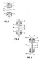
- Fig. 1 shows a snapshot of this situation.
- each of the film gripper takes with the pressed onto the suction surface 3 of its suction box 4 film, so that the film tube is opened to a, initially small, enclosed between the film webs A, B cross-section, as the Fig. 2 shows.
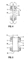
- suction gripping elements 2 are folded away at an angle of preferably ⁇ 90 ° from the film. They thereby also release a suction opening at the respective outwardly facing end face of the relevant suction box 4.
- the sections of the film webs A, B projecting outwardly beyond the cross-section bounded by the four film grippers are thereby sucked in by the released end faces of the suction boxes 4.
- the film gets into the region of the gap, which has opened by the pivoting back of the suction gripper elements 2 between them and the end faces of the suction boxes 4, see. Fig.
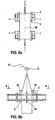
- the folding members are now approached by advancing in approximately horizontal direction.
- the folding members are here designed as narrow and elongated perpendicular to the plane extending folding plates 14.
- the Fig. 6b shows this in one Side view, the Fig. 6a in a view from above along that sectional plane AA, the in Fig. 6b is marked.
- the folding plates 14 are now moved further horizontally in the direction of the tube center of the approximately stretched to the square film tube. In this way, they fold the film tube, which has hitherto been opened approximately into a quadrilateral, from two of its outer sides C, D in the direction of the center of the hood M into a V shape.
- the film gripper are moved towards each other in pairs in the horizontal direction, so that the voltage of the folding plates 14 V-shaped folded sides of the film tube is kept controlled, or in any case overstretching of the film is prevented.
- This process shows the Fig. 7b Seen from the side or the Fig. 7a seen from above, in Fig. 7b by AA marked cutting plane.
- Fig. 8a and 8b finally show (each seen from the same point of view, as the previously discussed Fig. 6a and 6b or 7a and 7b) the position in which the two V-shaped folds are completely laid.
- the flat film tube previously clamped to form a quadrangle is folded in a V shape from its outer sides C, D which formerly had a 180 ° fold. in such a way that the two held by the suction boxes 4 and the suction / gripping means 2, opposing wide film webs A, B in the region of the outer sides of the hose no longer directly, but each including a V-shaped, with the Wrinkle tip to the tube center extending film folder lie on each other.
- This V-shaped fold is not only in the area of the film gripper 2, 4, but extends at least upwards into the area, which is to be subsequently closed, ie at the height of the subsequent closure point.
- the closing device 15 is activated.
- the closing in various ways, such. B. by folding and / or stapling done.
- a weld is pulled, which extends meaningfully over the entire width of the film tube away, but this is not mandatory.
- the hose as seen in the stripping, separated from the rest of the hose supply before the closing device.
- a horizontally guided blade 16 cuts through the hose.
- a hot wire can be used.
- the finished film hood can be covered over the charge or the already started coating of the film can be completed.
- the film grippers 2, 4 are designed and moved such that they can be used both to open, as seen in Abziehhraum, the extreme end of the hood and make the hood ready to cover, as well as serve the hood at the height the later closure point (just below) to open and so in cooperation with the Faltorganen 14 to accomplish the folding.
- FIGS. 9 and 10 illustrate this. While the Fig. 9 shows how relatively small V-shaped folds are formed, the shows Fig. 10 the formation of relatively large V-shaped folds.
- the film gripper from the position they were previously in folding under the Fig. 9 had engaged each other before folding the folds for the next hood along arrows E, Fig. 10 ,
- the sides A, B of the film hood which are grasped and held by the suction boxes 4 or the suction / gripping devices 2 are now shorter. Accordingly, the V-shaped folds can be pulled deeper from the now longer sides C, D forth inwardly towards the middle of the tube, in which the folding plates 14 are further retracted accordingly in the direction of the hood center M.
- the film tension is controlled in both cases, as described above, by a yielding in the direction of the arrows FL.
- Such a design of the film gripper 2, 4 also makes it possible to process flat tubes, which have different widths of their own. This ensures a high degree of flexibility. Because not all cases can be achieved with a flat tube one and the same width only on the variation of the wrinkle size optimal results.
- the charge sensors As soon as the charge sensors have detected the cross-section of the charge now to be packed in each case, they send a corresponding signal to the machine control, which in turn calculates the required size of the V-shaped folds and then takes the necessary precautions - such as the pairwise movement of the foil grippers along the arrows "E" and "FL” in the required position.
- the result is a biaxial motion - projected onto a two-axis coordinate system lying horizontally in space.
- the folding organs are controlled appropriately.
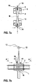
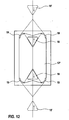
- a second embodiment operating in a similar manner as the first embodiment, show the Fig. 11 and 12 , This embodiment avoids it to open the film tube for the purpose of folding at a place other than its end of the hose in addition to lay there the wrinkles.
- the film tube is opened after passing through the film feed rollers 13 and aufgerfft in a known manner to a puller 19 for the subsequent hood.
- a puller 19 for the subsequent hood.
- an approximately roof-shaped cross-sectional profile (roof section 12 *) is formed between the opened-up section of the film tube and the still unopened section of the film tube.
- wedge-shaped folding elements 18 are pressed into the roof section 12 * from two sides, forcing it to have a V-shaped bend inwards.
- the position of the folding mechanism 18 and the still unfolded film area in Fig. 12 shown in dashed lines.
- the devices 15 provided here in the form of sealing bars for closing the film tube are brought together. They take the foil of the roof section 12 * with them, compress them inwards and also grasp the two V-shaped inward creases of the foil, which are thereby placed in each case into a V-shaped fold. Then it is welded. The V-shaped folds are welded to the film in contact with them and thus fixed. The film hood is then cut off by means of a knife 20 running along the welding bar. The finished film hood can now be stretched as usual and covered or pulled over and shrunk. The folding members 18 are here wedge-shaped with an inwardly directed towards the center of the film tube tip. This favors the V-shaped inward buckling of the film. Ideally, the acute angle "W" between 55 and 85 ° and can be adjusted if necessary, so it is adjustable, for example, depending on film thickness and strength, which leads to a good buckling, without the film by a too large peak is significantly overloaded.
- a third embodiment show the FIGS. 13 and 14 ,
- the flat tube during removal from its supply continuously (so to speak in a continuous process) to fold laterally - so that it is provided over its entire length with lateral V-shaped folds "VF" of the type in question here, before it enters the area of the machine in which the sealing of the film tube as well as the separation and coating of the hood takes place.
- the laying of the folds takes place with a hood stretch hood or hood shrinkage system which is unchanged from those described in the preceding exemplary embodiments, unless otherwise described below.
- two pairs of rollers 13a and 13b are now provided in this case.
- each carries a roll of Roller pair 13a and 13b a soft, supple and thus well-sealing wear layer, while the other roller consists at its periphery of smooth, usually ground metal. They press from both sides with the necessary pressure on the film between them.
- the beginning of the new film tube between the pairs of rollers 13 a and 13 b is inserted.
- the rollers of each pair of rollers are delivered against each other, so that the hose section B located between the two pairs of rollers 13a and 13b is practically completely sealed.
- the plant operator now injects, for. B. by piercing a corresponding nozzle 22a through the film, a certain amount of compressed air in the sealed tube section so that it forms a balloon.
- the injection hole is z. B. closed by an adhesive strip.
- the inflation of the tube section to be carried out in an inital manner can also be automated, but i. d. R. be made by the system operator to keep the equipment costs small. Because with a suitable selection of the lining and the contact pressure of the roller pairs 13a and 13b, the air losses will go to zero.
- the hose section B must then be inflated after each roll change only once, which is easy to accomplish by hand.
- the folding wedges 14 are delivered from two sides, which press the balloon-like tube section B at least in regions from two sides inwards in a V-shape and for this purpose preferably form a funnel-shaped geometry between them, through which the balloon-like tube section tapers onto the roller pair 13b ,
- guide surfaces 14a are additionally supplied to the foil balloon (here in a plane arranged approximately perpendicular thereto). These baffles 14a do not induce wrinkling, but prevent the balloon from undesirably evading or being undesirably deformed under the action of the folding wedges 14.
- the guide surfaces also preferably form a funnel-shaped geometry between them, through which the balloon-like hose section tapers onto the roller pair 13b.
- guide surfaces and folding wedges may also be rigidly mounted or displaced only as required for adjustment purposes.
- rollers of the roller pairs (with the film between them) roll on each other, the trapped compressed air is not lost. Instead, it can be said that it is "pumped" into the region of the film tube by the rollers from the region of the film tube which is about to move out of the area between the roller pairs 13a and 13b between the rollers of the roller pair 13b. which enters via the rollers of the roller pair 13a for the first time in the area between the roller pairs 13a and 13b.
- roller pairs 13a and 13b unlike purely exemplary in the FIGS. 13 and 14 shown, as a rule, will not include a horizontal plane between them.
- Fig. 15 instead, they are placed in the machine so as to enclose an approximately vertical plane - namely in the ascending region, in which the flat tube, after its removal from the supply in the machine, is led upwards and then from above as a hood over the to be pulled to be packed items, or, instead, in the descending region, in which the flat tube from the top coming down in the direction of the objects to be packaged is performed.
- the Fig. 15 illustrates these two alternatives summarized in one picture. In the left half of the picture is shown how the of the FIGS.
- folding device 13a, 13b, 14, 14a
- the machine can be extremely compact, as otherwise used only with low intensity space is used and there (important in hood shrinking machines) of the blown and thus sensitive film section is kept outside the waste heat zone.
- the means for folding 13a ', 13b', 14, 14a '
- the means for folding can also be arranged in the descending region of the machine, in the vicinity of the charge to be packaged.
Abstract
Description
Die Erfindung betrifft ein Verfahren und eine Vorrichtung zum Verpacken eines Gutstapels gemäß dem Oberbegriff des Anspruchs 1 (Verfahren) bzw. des Anspruchs 7 (Vorrichtung).The invention relates to a method and a device for packaging a stack of goods according to the preamble of claim 1 (method) or of claim 7 (device).
Gattungsgemäße Verpackungsanlagen arbeiten entweder nach dem sog. Haubenschrumpfverfahren oder nach dem sog. Haubenstretchverfahren. In beiden Fällen wird eine Folienhaube über die zu verpackenden Gegenstände gezogen (im Regelfall von oben). Im Falle eines Haubenschrumpfverfahrens wird die Folienhaube anschließend durch Wärmeeinwirkung zum Schrumpfen gebracht. Sie zieht sich dadurch zusammen und hält so den Gutstapel zusammen. Im Falle des Haubenstretchverfahrens wird die Haube vor und ggf. während des Überziehens elastisch federnd gedehnt, horizontal und/oder vertikal. Sie legt sich auf Grund dessen unter Vorspannung an den zu verpackenden Gutstapel an und hält diesen so zusammen.Generic packaging systems work either after the so-called. Hood shrinkage process or after the so-called. Hood stretch process. In both cases, a foil hood is pulled over the objects to be packed (usually from above). In the case of a hood shrinking process, the film hood is then brought to heat shrinkage by heat. She pulls herself together and holds the stack together. In the case of the hood stretching method, the hood is stretched elastically, before and optionally during the coating, horizontally and / or vertically. Due to this, it lays under pretension against the stack to be packaged and holds it together.
Eine nach dem sogenannten Haubenschrumpfverfahren arbeitende Vorrichtung ist beispielsweise aus der
Bei dem von dieser Anlage zum Herstellen der Verpackungshauben verwendeten Folienschlauch handelt es sich um einen vom Folienhersteller vorgefertigten und dann zu einer Vorratsrolle aufgewickelten Seitenfaltenschlauch, d. h. um einen flach zusammengelegten Schlauch, der in seinem zusammengelegtem Zustand entlang seiner beiden Seiten V-förmige Falten besitzt - derart, dass die beiden die Hauptflächen des Folienschlauchs bildenden Folienbahnen im Bereich der Außenseiten des Schlauchs nicht unmittelbar, sondern jeweils unter Einschluss einer V-förmigen, sich mit der Faltenspitze zur Schlauchmitte hin erstreckenden Folienfalte aufeinander liegen.The film tube used by this system for producing the packaging hoods is a gusseted tube prefabricated by the film manufacturer and then wound into a supply roll, d. H. around a flat folded tube, which in its folded state along its two sides has V-shaped folds - such that the two film webs forming the main surfaces of the film tube not immediately in the region of the outer sides of the tube, but each including a V-shaped, lying with the pleat tip to the middle of the tube extending film fold each other.
Seitenfaltenschläuche sind auf Grund ihrer speziellen Vorbehandlung beim Folienhersteller relativ teuer. Zudem tragen Seitenfaltenschläuche auf der Vorratsrolle relativ dick auf, so dass auf einer Vorratsrolle mit einem maschinenseitig vorgegebenen Maximaldurchmesser nur eine geringere Anzahl laufender Meter (etwa 50 %) eines Seitenfaltenschlauchs unterzubringen sind, verglichen mit der Anzahl an laufenden Metern die auf eine derartigen Vorratsrolle passen, wenn ein Flachschlauch aufgewickelt wird. - ein Flachschlauch, der aus zwei einstückig hintereinander verbundenen Folienbahnen besteht, die lediglich an ihren Kanten einmal um 180 Grad gefaltet sind und dadurch auf ganzer Breite flach aufeinanderliegen.Gusseted tubes are relatively expensive because of their special pretreatment with the film manufacturer. In addition, gusseted tubing on the supply roll is relatively thick, such that only a smaller number of running meters (about 50%) of gusseted tubing is to be accommodated on a supply roll having a maximum machine diameter as compared to the number of running meters that fit such a supply roll. when a flat hose is wound up. - A flat tube, which consists of two integrally connected one behind the other film webs, which are folded only once at their edges by 180 degrees and thus lie flat on the entire width.
Es sind daher auch Maschinen bekannt, die statt der fertig vorkonfektionierten Seitenfaltenschläuche sog. Flachschläuche verarbeiten. Solange keine besonderen Maßnahmen getroffen werden, ergibt sich bei der Verarbeitung von Flachschläuchen zu Folienhauben das Problem, dass nach dem Überziehen der Folienhaube über den zu verpackenden Gutstapel an dessen Oberseite zwei zipfelförmige Haubenabschnitte abstehen. Dieses Problem der Zipfelbildung wird von der
Diese zipfelartig abstehenden Haubenabschnitte sind optisch unschön. Sie beinträchtigen das Verpackungsergebnis auch in technischer Hinsicht. Die zipfelartigen Haubenabschnitte werden auf Grund ihres Abstehens beim transportbedingten Handling der Ladung (z. B. dem Aufeinanderstapeln einzelner Ladungen) leicht eingeklemmt bzw. beschädigt. Hierdurch wird der Feuchtigkeitsschutz der Verpackung beeinträchtigt. Wird eine solche Haube als Schrumpffolienhaube ausgeführt, kann es sein, dass die abstehenden Zipfel im Zuge der zum Zwecke des Schrumpfens vorgenommenen Erwärmung sehr weich werden. Unter Umständen kommen sie wegen ihres Abstehens sogar zu dicht an die zum Schrumpfen eingesetzte Wärmequelle heran und werden überhitzt. Wie dem auch sei - sie sacken zumindest in sich zusammen und kommen in klebrig-teigigem Zustand in Kontakt mit umliegenden Folienbereichen. Unter Umständen verschmelzen dann mehrere Folienlagen miteinander. Dort, wo verschiedene Folienschichten miteinander verschmolzen sind, entwickelt die sich so ergebende dickere Folienlage extreme Schrumpfkräfte. Es kann dann passieren, dass die Folie am Übergang zwischen der regulären Schicht und der miteinander verklebten Schichten dünngezogen wird, d. h. am Ende dort eine örtliche Dünnstelle aufweist und unter dem Einfluss der transportbedingten Kräfte irgendwann reißt.These jagged protruding hood sections are visually unattractive. They also affect the packaging result in technical terms. The jagged hood sections are easily pinched or damaged due to their protrusion during transport-related handling of the load (eg stacking of individual loads). As a result, the moisture protection of the packaging is impaired. If such a hood is designed as a shrink-film hood, it may be that the protruding corners in the course of the made for the purpose of shrinking Heating up to be very soft. Under certain circumstances, they come too close to the heat source used for shrinking because of their distance and are overheated. Anyway, they at least collapse and come in sticky doughy state in contact with surrounding film areas. Under certain circumstances, then melt several layers of film together. Where different film layers are fused together, the resulting thicker film layer develops extreme shrinkage forces. It can then happen that the film is pulled thin at the transition between the regular layer and the layers glued together, ie at the end there has a local thin point and under the influence of transport-related forces breaks at some point.
Auch bei Verwendung einer solchen Haube als Stretchfolienhaube ergeben sich Nachteile. Denn im Bereich der Zipfel kann sich die Folie u. U. unzulässig lockern.Even when using such a hood as a stretch film hood disadvantages. Because in the area of the corner, the film u. U. inadmissible loose.
Um die störenden Zipfel der Folienhaube zu vermeiden, schlägt die
Aus der
Angesichts dessen ist es Aufgabe der Erfindung, ein Verpackungsverfahreri anzugeben bzw. eine Verpackungsanlage zu schaffen, die sich zum maschineninternen Herstellen der Folienhauben eines Flachschlauchs bedient, aber die beim Verpacken mit aus Flachschlauch hergestellten Hauben typischerweise auftretende, störende Zipfelbildung an der fertigen Haube vermeidet und die auf ein unerwünschtes Nachbehandeln der über den Gutstapel gezogenen Haube zur Beseitigung von Zipfel verzichtet.In view of this, it is an object of the invention to provide a Verpackungsverfahreri or to create a packaging system that makes use of the machine-internal production of the film hoods of a flat hose, but the packaging when produced with flat-tube hoods typically occurring, annoying earing the finished hood avoids and waives an unwanted after-treatment of the pulled over the stack of goods to eliminate Zipfel.
Diese Aufgabe wird durch ein Verfahren mit den Merkmalen von Anspruch 1 und einer Vorrichtung mit den Merkmalen von Patentanspruch 7 gelöst. Vorteilhafte Weiterbildungen der Erfindung sind Gegenstand der Unteransprüche.This object is achieved by a method having the features of
Der in Form eines Flachschlauchs eingesetzte Schlauch wird erst nach dem endgültigen Abziehen von seinem Vorrat, und vor dem Verschließen, von seinen Außenseiten her derart V-förmig eingefaltet wobei, die zwei Folienbahnen im Bereich der Außenseiten des Schlauchs und auf der Höhe der Verschlussstelle während des Verschließens jeweils nicht mehr unmittelbar, sondern unter Einschluss einer V-förmigen, sich mit der Faltenspitze zur Schlauchmitte hin erstreckenden Folienfalte aufeinander liegen und wobei das Verschließen derart erfolgt, dass die V-förmigen Falten und die sie unmittelbar umgebenden Bereiche der Folienbahn im Verschlussbereich relativ zueinander fixiert werden. Bei der Durchführung des Verfahrens kommt eine Vorrichtung mit den Merkmalen von Patentanspruch 7 zur Anwendung.The hose used in the form of a flat hose is folded in such a V-shape only after the final removal from its stock, and before closing, from its outer sides, the two film webs in the region of the outer sides of the hose and at the level of the closure point during the Closing in each case no longer directly, but with the inclusion of a V-shaped, with the pleat tip to the tube center extending towards film folds lie on each other and wherein the closure is such that the V-shaped folds and immediately surrounding areas of the film web in the closure area relative to each other be fixed. In carrying out the method, a device having the features of claim 7 is used.
Auf diese Art und Weise wird der Schlauch in dem Bereich, in dem er später verschlossen wird, vor dem Verschließen sauber zusammengelegt. Die nach innen eingefalteten Bereiche der Folie, die ansonsten überflüssig wären und zur Zipfelbildung geführt hätten, werden im Zuge des Verschließens des Schlauchs fixiert. Beim anschließenden (ggf. auch nur vervollständigenden) Überziehen kommt es auf diese Art und Weise von vorneherein gar nicht erst zu einer Zipfelbildung. Die nachträgliche Beseitigung von Zipfeln entfällt.In this way, the hose in the area in which it is sealed later, neatly folded before closing. The folded-in areas of the film, which would otherwise be superfluous and would have led to earing, are fixed in the course of closing the tube. In the subsequent (possibly only completing) coating it comes in this way from the outset not only to a Zipfelbildung. The subsequent removal of corners is eliminated.
Einer der entscheidenden Vorteile dabei ist, dass sich das Verfahren zur Herstellung der Haube eines Flachschlauches bedient. Denn simpler Flachschlauch ist deutlich günstiger als vorgefertigter Seitenfaltenschlauch und zudem flexibler verwendbar - die Anwendungsbandbreite eines vorgefertigten Seitenfaltenschlauchs ist durch die vorausgewählte Größe der Seitenfalten begrenzt. Gleichwohl müssen trotz Einsatz eines Flachschlauchs keine Abstriche bei der Qualität der fertigen Verpackung hingenommen werden.One of the key advantages of this is that the method of making the hood of a flat hose uses. Because simple flat hose is much cheaper than prefabricated gusseted hose and also more flexible - the application range of a prefabricated gusseted hose is limited by the preselected size of the gussets. Nevertheless, despite the use of a flat hose no compromise on the quality of the finished packaging must be accepted.
Auch im Hinblick auf die Zahl der pro Stunde verpackbaren Ladungseinheiten ergeben sich in jedem Fall Vorteile. Da auf einer Rolle, deren Maximaldimensionen fest vorgegeben sind, deutlich mehr laufende Meter Flachschlauch aufgewickelt sind, werden die Intervalle, in denen der Verpackungsprozess zum Zwecke des Einlegens einer neuen Folienrolle stillgesetzt werden muss, etwa 50% kleiner. Legt man nun die benötigten V-förmigen Falten über die gesamte Schlauchlänge hinweg im Durchlaufverfahren (meist ohne dass irgendeine Zusatzbewegung notwendig ist) ergibt sich ein klarer Zeitvorteil. Gleiches gilt, wenn nur lokal Falten gelegt werden und dabei auf ein zusätzliches lokales Aufziehen des Schlauches verzichtet wird. Selbst wenn die Zusatzbewegung "Schlauch lokal aufziehen und einfalten" durchgeführt wird, um besonders präzise Falten zu legen, bleibt meist per saldo noch ein gewisser Zeitvorteil.There are also advantages in terms of the number of load units to be packaged per hour. Since on a roll whose maximum dimensions are fixed, significantly more running meter flat hose are wound, the intervals in which the packaging process for the purpose of inserting a new roll of film must be shut down, about 50% smaller. Now you put the required V-shaped Folding over the entire hose length in the continuous process (usually without any additional movement is necessary) results in a clear time advantage. The same applies if only local wrinkles are set and it is dispensed with an additional local mounting of the hose. Even if the additional movement "pulling and unfolding the hose locally" is carried out in order to create particularly precise wrinkles, there is usually a certain time advantage on balance.
Um Präzisionsfalten zu legen, wird der Schlauch vor dem Einfalten auf seiner entsprechenden Höhe so geöffnet, dass er dort einen etwa viereckigen Schlauchquerschnitt bildet. Daraufhin wird mittels geeigneter Faltorgane die Folie an zwei gegenüberliegenden Seiten dieses in etwa viereckigen Schlauchquerschnitts V-förmig zur Schlauchmitte hin geführt. Dann wird der Schlauchquerschnitt verkleinert, so dass sich an den Seiten, die nach innen geführt werden, jeweils eine mit ihrer Spitze zur Mitte des Schlauchquerschnitts weisende V-förmige Falte zwischen die beiden anderen den Schlauchquerschnitt begrenzenden Seiten legt.In order to place precision folds, the tube is opened at its corresponding height prior to folding in such a way that it forms an approximately quadrangular tube cross section there. Then, by means of suitable folding members, the film is guided on two opposite sides of this roughly quadrangular tube cross-section in a V-shape towards the middle of the tube. Then, the tube cross-section is reduced, so that on the sides, which are guided inwards, each with its tip to the center of the tube cross-section facing V-shaped fold between the other two the hose cross-section bounding sides sets.
Auf diese Art und Weise ist es sehr einfach möglich, insbesondere V-förmige Falten in Form eines einfachen "V" präzise und störungsfrei zu legen - der Begriff V-förmig ist funktional zu verstehen und beschreibt das Prinzip der Falte. Eine V-förmige Falte kann beispielsweise auch die Form eines doppelten V, d. h. zweier ziehharmonikaförmig nebeneinander liegender "VV" haben. Bevorzugt ist allerdings eine V-förmige Falte in Form eines einfachen "V". Eine solche Falte lässt sich bei weitem am einfachsten und zuverlässigsten legen. Es versteht sich von selbst, dass das "V" der V-förmigen Falte nahezu parallel gedrückte Schenkel aufweist, sobald der Folienschlauch nach dem Faltenlegen ggf. zeitweilig wieder vollständig flach zusammengelegt wird - etwa um über weitere Transport- oder Umlenkwalzen dem Abschnitt der Maschine zugeführt zu werden, in dem das Verschließen, Abtrennen usw. erfolgt.In this way, it is very easy, especially V-shaped folds in the form of a simple "V" precise and trouble-free to lay - the term V-shaped is functional to understand and describes the principle of the fold. For example, a V-shaped fold may also take the form of a double V, d. H. two concertina-shaped juxtaposed "VV" have. However, a V-shaped fold in the form of a simple "V" is preferred. Such a fold is by far the easiest and most reliable. It goes without saying that the "V" of the V-shaped fold has almost parallel pressed legs, as soon as the film tube after folding is possibly completely temporarily folded flat again - about fed to the section of the machine about more transport or guide rollers in which the closing, separating, etc. takes place.
Dabei werden die Seiten des Schlauchquerschnitts, die nicht zur Bildung einer V-förmigen Falte nach innen geführt werden, aufeinanderzubewegt. Auf diese Art und Weise kann während des Legens der V-förmigen Falten sehr einfach eine kontrollierte Folienspannung aufrechterhalten werden, so dass saubere Falten gelegt werden ohne dass die Gefahr einer Überbeanspruchung der Folie besteht.The sides of the tube cross-section, which are not guided inwardly to form a V-shaped fold, are moved towards one another. In this way, it is very easy to maintain a controlled film tension during the laying of the V-shaped pleats, so that clean pleats are laid without the risk of overstressing the film.
Die Größe der beiden V-förmigen Falten (d. h. der Abstand zwischen der Spitze des V und dem Ende der beiden Schenkel des V) wird dadurch eingestellt, dass die Länge der beiden Seiten des Schlauchquerschnitts, die beim Legen der V-förmigen Falten aufeinanderzubewegt werden und die V-förmigen Falten zwischen sich aufnehmen, vor Beginn des Faltenlegens entsprechend gewählt wird. Auf diese Art und Weise wird es möglich, die Größe der Seitenfalten und damit die Größe der Folienhaube ideal an die Kontur der jeweils zu verpackenden Ladung anzupassen. Während nämlich nahezu ideal quaderförmige Ladungen praktisch keine oder nur relativ kleine V-förmigen Falten benötigen, ist es bei stark vom quadratischen Querschnitt abweichenden Ladungen mit deutlich rechteckigem Querschnitt erforderlich, relativ große V-förmige Falten vorzusehen, um Zipfelbildung zu vermeiden. Eine möglichst gut angepasst gewählte Größe der V-förmigen Falten ist insbesondere auch für die Reißfestigkeit bzw. Haltbarkeit der Haube im Verschlussbereich wichtig. Sind nämlich die V-förmigen Falten nicht korrekt dimensioniert, dann treten z. B. in der die Haube verschließenden Schweißnaht an der Stelle des Übergangs von vier auf zwei Schichten erheblich Zugkräfte auf. Diese führen zu Einrissen, ggf. sogar zum vollständigen Zerreißen der Folienhaube. Diese Gefahr besteht in besonderem Maße bei Stretchfolienhauben. Sie ist zumindest im Ansatz aber auch dort zu verzeichnen, wo die Haube im Bereich einer nach dem Überziehen schlecht sitzenden und damit Spannungen ausgesetzten Schweißnaht geschrumpft wird.The size of the two V-shaped pleats (ie the distance between the top of the V and the end of the two legs of the V) is adjusted by adjusting the length of the two sides of the tube cross-section which are moved towards each other when the V-shaped pleats are laid to pick up the V-shaped folds between them Beginning of folding is chosen accordingly. In this way, it is possible to adjust the size of the gussets and thus the size of the film hood ideally to the contour of each charge to be packaged. For while virtually ideal parallelepipedic charges require virtually no or only relatively small V-shaped folds, it is necessary to provide relatively large V-shaped folds in the case of cargoes of significantly rectangular cross-section that deviate greatly from the square cross-section in order to avoid earing. A size of the V-shaped folds chosen as well as possible is particularly important for the tear strength or durability of the hood in the closure area. Namely, the V-shaped folds are not dimensioned correctly, then occur z. B. in the hood closing the weld at the point of transition from four to two layers significantly tensile forces. These lead to tears, possibly even to the complete rupture of the film hood. This danger is especially true in stretch film hoods. It is at least in the approach but also recorded where the hood is shrunk in the area of a badly fitting after the coating and thus exposed to stress weld.
Vorrichtungsseitig wird die angegebene Aufgabe durch die Vorrichtung gemäß Anspruch 7 gelöst.On the device side, the specified object is achieved by the device according to claim 7.
Weitere Vorteile, Merkmale und Einzelheiten werden bei der nachfolgenden detaillierten Beschreibung eines Ausführungsbeispiels anhand der beigefügten Zeichnungen deutlich. Die
- Fig. 1
bis 5 - eine als solche bekannte Einrichtung zum Öffnen eines Folienschlauchs mittels Foliengreifern;
- Fig. 6a
- eine Aufsicht auf die als solche bekannte Einrichtung zum Öffnen der Folienhaube in dem Moment, in dem die Faltorgane gemäß eines ersten Ausführungsbeispiels in Wirkung zu treten beginnen;
- Fig. 6b
- die von
Fig. 6a gezeigte Anordnung in Seitenansicht; - Fig. 7a
- das Zusammenwirken der von
Fig. 6a und 6b gezeigten Foliengreifer und Faltorgane in einem fortgeschrittenen Stadium des Einfaltens zweier Seiten des Folienschlauchs; - Fig. 7b
- die von
Fig. 7a gezeigte Anordnung in Seitenansicht; - Fig. 8a
- das Zusammenwirken der von den
Fig. 6a und 6b gezeigten Foliengreifer und Faltorgane, nachdem die Falten vollständig gelegt wurden und die Folienhaube in Abziehrichtung gesehen vor (oberhalb) den Foliengreifern und den Faltorganen zugeschweißt und abgetrennt wird; - Fig. 8b
- die von
Fig. 8a gezeigte Anordnung in Seitenansicht; - Fig. 9
- die Foliengreifer und Faltorgane der ersten Ausführungsform in einer Variante, bei der die Foliengreifer zweiachsig in der Horizontalebene verfahrbar sind um so die Größe der V-förmigen Falten einstellen zu können und hier so verfahren wurden, dass kleine V-förmige Falten gelegt werden;
- Fig. 10
- die von
Fig. 9 gezeigten Foliengreifer und Faltorgane, wobei die Foliengreifer hier so positioniert wurden, dass große V-förmige Falten gelegt werden; - Fig. 11
- ein zweite Ausführungsform bei der die Falten zur Realisierung höherer Taktzeiten in den Dachabschnitt des Folienschlauches gelegt werden;
- Fig. 12
- eine teilgeschnittene Aufsicht auf die von
Fig. 11 gezeigte zweite Ausführungsform; - Fig. 13
- eine dritte Ausführungsform, die es ermöglicht die falten im Durchlaufverfahren zu legen, allerdings in einer Position, bevor die Faltplatten zugestellt wurden um so auf den Schlauch einzuwirken;
- Fig. 14
- die dritte Ausführungsform zu Schichtbeginn oder nach Wechsel der Vorratsrolle für den Folienschlauch;
- Fig. 15
- Anlagenschema zur Realisierung der dritten Ausführungsform.
- Fig. 1 to 5
- a device known as such for opening a film tube by means of film grippers;
- Fig. 6a
- a plan view of the known as such means for opening the film hood at the moment in which the folding members according to a first embodiment begin to take effect;
- Fig. 6b
- the of
Fig. 6a arrangement shown in side view; - Fig. 7a
- the interaction of the
Fig. 6a and 6b shown film gripper and Faltorgane in an advanced stage of Einfalts two sides of the film tube; - Fig. 7b
- the of
Fig. 7a arrangement shown in side view; - Fig. 8a
- the interaction of the
Fig. 6a and 6b shown film gripper and Faltorgane after the wrinkles have been completely laid and the film hood in Abziehrichtung seen before (above) the film grippers and the Faltorganen welded and separated; - Fig. 8b
- the of
Fig. 8a arrangement shown in side view; - Fig. 9
- the film gripper and Faltorgane the first embodiment in a variant in which the film gripper are biaxially movable in the horizontal plane so as to be able to adjust the size of the V-shaped folds and have been moved so that small V-shaped folds are placed;
- Fig. 10
- the of
Fig. 9 shown film gripper and Faltorgane, the film gripper have been positioned here so that large V-shaped folds are placed; - Fig. 11
- a second embodiment in which the folds are placed in the roof portion of the film tube to realize higher cycle times;
- Fig. 12
- a partially cut top view of the
Fig. 11 shown second embodiment; - Fig. 13
- a third embodiment, which allows the folds to be laid in a continuous process, but in a position before the folding plates were delivered so as to act on the tube;
- Fig. 14
- the third embodiment at the beginning of the shift or after changing the supply roll for the film tube;
- Fig. 15
- Plant schematic for the realization of the third embodiment.
Für alle nachfolgend beschriebenen Ausführungsbeispiele gilt, dass die Verpackungsanlage und ihre grundsätzlichen Komponenten etwa so angeordnet sein können, wie von der
Die Mittel zum Legen der V-förmigen Falten, die hier im wesentlichen aus den sogleich näher zu beschreibenden Foliengreifern und den diesen zugeordneten Faltorganen bestehen, sind bei den ersten beiden Ausführungsbeispielen in Abziehrichtung des Folienschlauchs gesehen hinter den Vorschubwalzen 13 (die bei der
Der Folienschlauch ist zu dem hier (an Hand der Figuren) erörterten Zeitpunkt entweder geöffnet und wenigstens zum Teil bereits über die Ladung gezogen. Alternativ ist er, etwa wenn die Anlage zur Durchführung eines Haubenstretchverfahrens konzipiert ist, zu diesem Zeitpunkt auf die Refforgane aufgerefft. In beiden Fällen ist das obere Ende des Folienschlauchs zu dem hier zu betrachtenden Zeitpunkt noch mit dem bevorrateten Flachschlauch verbunden.The film tube is either open at the time discussed here (on the basis of the figures) and at least partially pulled over the load. Alternatively, it is, for example, when the plant is designed to carry out a hood stretching process, aufgerefft at this time on the Refforgane. In both cases, the upper end of the film tube at the time to be considered here is still connected to the stored flat hose.
Die Foliengreifer werden nun in horizontaler Richtung soweit verfahren, dass sie (in Abziehrichtung gesehen) knapp hinter dem später zur Bildung einer Folienhaube zu verschließenden Abschnitt des Folienschlauchs Folienhaube zu liegen kommen. Der Folienschlauch ist an dieser Stelle noch zumindest nahezu ungeöffnet, d. h. die beiden den Flachfolienschlauch bildenden Folienbahnen liegen plan aufeinander.The film grippers are now moved in the horizontal direction so far that they (as seen in the stripping) come to rest just behind the later to form a film hood to be closed section of the film tube film hood. The film tube is still at least almost unopened at this point, d. H. the two film webs forming the flat film tube lie flat against each other.
Die Foliengreifer sind im Prinzip so aufgebaut, wie aus der
Jeder der Foliengreifer (2, 4) besteht aus einem Saugkasten 4, der ein Saug/Greifelement 2 trägt. Jeder Saugkasten weist an seiner der Folie zugewandten Seite eine Saugfläche 3 auf. Letztere besteht etwa aus einer entsprechenden Öffnung, welche mit einem Gitter abgedeckt ist. Das Saug-Greifelement 2 ist schwenkbar an dem Saugkasten 4 angelenkt.Each of the film grippers (2, 4) consists of a
Sobald die vier Saugkästen 4 der Foliengreifer mit der Folien in Kontakt gebracht worden sind, wird durch Einschalten des entsprechenden Sauggebläses Vakuum angelegt, so dass die Folienbahnen A, B abschnittweise an die Saugflächen 3 angedrückt werden. Die
Sodann werden die Foliengreifer paarweise in horizontaler Richtung auseinandergefahren. Jede der Foliengreifer nimmt die an der Saugfläche 3 seines Saugkastens 4 angedrückte Folie mit, so dass der Folienschlauch zu einem, zunächst noch kleinen, zwischen den Folienbahnen A, B eingeschlossenen Querschnitt geöffnet wird, so wie dies die
Dann werden die jeweils schwenkbar an den Saugkästen 4 gelagerten Saug-Greifelemente 2 in einem Winkel von vorzugsweise < 90° von der Folie weggeklappt. Sie geben dadurch auch eine Saugöffnung an der jeweiligen nach außen gewandten Stirnseite des betreffenden Saugkastens 4 frei. Die nach außen über den von den vier Foliengreifern umgrenzten Querschnitt hinausragende Abschnitte der Folienbahnen A, B werden dadurch von den freigegebenen Stirnseiten der Saugkästen 4 angesaugt. So gerät die Folie in den Bereich des Spalts, der sich durch das Zurückschwenken der Saug-Greifelemente 2 zwischen diesen und den Stirnseiten der Saugkästen 4 aufgetan hat, vgl.
Daran anschließend werden die Foliengreifer paarweise in horizontaler Richtung weiter auseinander gefahren, so dass Flachschlauch nun zu einem in etwa viereckigen Querschnitt geöffnet ist, so wie von
Bis hierher entspricht die Handhabung des Folienschlauchs vom Grundsatz her in etwa dem von der
An diejenigen Seiten C, D, auf die im wesentlichen nicht unmittelbar durch die Foliengreifer eingewirkt wird, werden nun durch Zustellen in etwa horizontaler Richtung die Faltorgane herangefahren. Die Faltorgane sind hier als schmale und sich länglich senkrecht zur Zeichenebene erstreckende Faltplatten 14 ausgeführt. Die
Die Faltplatten 14 werden nun weiter horizontal in Richtung der Schlauchmitte des etwa zum Viereck aufgespannten Folienschlauchs verfahren. Sie falten auf diese Art und Weise den bislang in etwa zu einem Viereck geöffneten Folienschlauch von zwei seiner Außenseiten C, D her in Richtung der Haubenmitte M V-förmig ein. Während dieses Einfaltens werden die Foliengreifer paarweise in horizontaler Richtung aufeinanderzubewegt, so dass die Spannung der von den Faltplatten 14 V-förmig eingefalteten Seiten des Folienschlauchs kontrolliert gehalten wird, bzw. jedenfalls eine Überdehnung der Folie verhindert wird. Diesen Vorgang zeigt die
Die
Jetzt wird, was die
Sodann wird der Schlauch, in Abziehrichtung gesehen, vor der Verschließeinrichtung vom übrigen Schlauchvorrat abgetrennt. Etwa in dem etwa eine horizontal geführte Klinge 16 den Schlauch durchschneidet. Alternativ kann auch ein Heißdraht eingesetzt werden.Then the hose, as seen in the stripping, separated from the rest of the hose supply before the closing device. For example, in which about a horizontally guided
Nun kann die fertige Folienhaube über die Ladung übergezogen bzw. das bereits zuvor begonnene Überziehen der Folie vervollständigt werden.Now the finished film hood can be covered over the charge or the already started coating of the film can be completed.
Vorteilhafterweise sind die Foliengreifer 2, 4 derart ausgebildet und verfahrbar, dass sie sowohl dazu eingesetzt werden können, das, in Abziehrichtung gesehen, äußerste Ende der Haube zu öffnen und die Haube überziehfertig zu machen, als auch dazu dienen können, die Haube auf der Höhe der späteren Verschlussstelle (knapp unterhalb) zu öffnen und so in Zusammenwirkung mit den Faltorganen 14 das Faltenlegen zu bewerkstelligen.Advantageously, the
Hervorzuheben ist noch, dass bei dem hier beschriebenen ersten Ausführungsbeispiel nur örtlich im Bereich der späteren Verschlussstelle V-förmige Falten gelegt werden. Dies schont die Folie und schützt vor unnötigen Folienrissen, die den gesamten Prozess aufhalten. Denn es ist nicht nötig, über die gesamte Länge der späteren Folienhaube hinweg V-förmige Falten zu legen. Dies, weil letztere außerhalb des Nahbereichs der Verschlussstelle beim Überziehen der Haube über die Ladung ja doch wieder aufgezogen werden. Das hat seinen Grund darin, dass außerhalb des Nahbereichs der Verschlussstelle im Regelfall der gesamte Folienquerschnitt gebraucht wird, um die zu verpackende Ladung zu umhüllen.It should also be emphasized that in the first exemplary embodiment described here, only locally in the region of the later closure point are V-shaped folds laid. This protects the film and protects against unnecessary film tears that stop the entire process. Because it is not necessary to put over the entire length of the later film hood away V-shaped folds. This is because the latter, outside the vicinity of the closing point, are pulled up again when the hood is pulled over the load. The reason for this is that, outside the vicinity of the closure, as a rule, the entire film cross-section is needed in order to envelop the charge to be packaged.
Gestaltet man die Foliengreifer 2, 4 so, dass sie paarweise in einer ersten horizontalen Richtung aufeinander zu und voneinander weg fahren können und dass sie paarweise (aber in anderer Paarung) in einer zweiten horizontalen Richtung, orthogonal zur ersten horizontalen Richtung, aufeinander zu und voneinander weg fahren können, dann lässt sich auf sehr einfache Art und Weise die gewünschte Größe einstellen, die die V-förmigen Falten bei ihrem Legen erhalten. Auf diese Art und Weise ist es möglich, in individueller Anpassung an den Querschnitt der jeweils zu verpackenden Ladung V-förmige Falten von optimaler Größe zu legen - so dass die für diese, individuell zu verpackende Ladung hergestellte Foliehaube optimal an der Ladung "sitzt".Forming the
Die
Zu diesem Zweck wurden die Foliengreifer aus der Position, die sie zuvor beim Faltenlegen im Rahmen der
Auf die gleiche Art und Weise können, durch entsprechendes paarweises Auseinanderfahren der Foliengreifer längs der durch die Pfeile E gekennzeichneten Achsen auch Folienhauben mit kleineren V-förmigen Falten hergestellt werden.In the same way, by corresponding pairwise moving apart of the film gripper along the axes indicated by the arrows E and film hoods can be made with smaller V-shaped folds.
Die Folienspannung wird in beiden Fällen, wie vorbeschrieben, durch ein Nachgeben in Richtung der Pfeile FL gesteuert.The film tension is controlled in both cases, as described above, by a yielding in the direction of the arrows FL.
Eine derartige Gestaltung der Foliengreifer 2, 4 ermöglicht es des Weiteren, Flachschläuche zu verarbeiten, die von Hause aus unterschiedliche Breiten haben. Dies gewährleistet eine hohe Flexibilität. Denn nicht in allen Fällen lassen sich mit einem Flachschlauch ein und derselben Breite nur über die Variation der Faltengröße optimale Ergebnisse erzielen.Such a design of the
Die Variabilität im Hinblick auf die Größe der V-förmigen Falten bringt erhebliche Vorteile. Wo früher entweder die Folienrollen gewechselt werden mussten, oder aber Maschinen, die verschiedene Folien bevorraten und auf Abruf zum Einsatz bringen können, erforderlich waren, genügt heute eine Maschine mit einem einzigen Folienvorrat. Dadurch wird nicht nur der maschinelle Aufwand kleiner und die Qualität der fertigen Verpackung höher. Vielmehr steigt auch die Taktgeschwindigkeit. Und zwar selbst dann, wenn die zu verpackenden Ladungen immer wieder stark unterschiedliche Dimensionen aufweisen. Denn ein Umrüsten der Maschine (auch wenn es automatisch möglich sein mag) erübrigt sich jeweils. Sobald die Ladungssensoren den Querschnitt der nun jeweils zu verpackenden Ladung erfasst haben, übermitteln sie entsprechendes Signal an die Maschinensteuerung, die ihrerseits die benötigte Größe der V-förmigen Falten errechnet und dann die nötigen Veranlassungen trifft - wie etwa das paarweise Verfahren der Foliengreifer längs der Pfeile "E" und "FL" in die benötigte Position. Die Bewegung erfolgt dabei im Ergebnis zweiachsig - projiziert auf ein gedachtes horizontal im Raum liegendes, zweiachsiges Koordinatensystem. Die Faltorgane werden passend angesteuert.The variability in terms of the size of the V-shaped folds brings significant benefits. Where previously either the rolls of film had to be changed, or machines that could store different films and put them on call were required, today a machine with a single supply of film is sufficient. As a result, not only the mechanical complexity is smaller and the quality of the finished packaging higher. Rather, the clock speed increases. And even then, even if the loads to be packaged always have very different dimensions. Because a conversion of the machine (even if it may be automatically possible) is unnecessary in each case. As soon as the charge sensors have detected the cross-section of the charge now to be packed in each case, they send a corresponding signal to the machine control, which in turn calculates the required size of the V-shaped folds and then takes the necessary precautions - such as the pairwise movement of the foil grippers along the arrows "E" and "FL" in the required position. The result is a biaxial motion - projected onto a two-axis coordinate system lying horizontally in space. The folding organs are controlled appropriately.
Eine zweites, in ähnlicher Weise wie das erste Ausführungsbeispiel arbeitendes Ausführungsbeispiel zeigen die
Bei diesem Ausführungsbeispiel wird der Folienschlauch nach dem Passieren der Folienvorschubwalzen 13 geöffnet und in bekannter Art und Weise auf eine Überzieheinrichtung 19 für die spätere Haube aufgerefft. Daraufhin bildet sich zwischen dem aufgerefften Abschnitt des Folienschlauchs und dem noch ungeöffneten Abschnitt des Folienschlauchs ein etwa dachförmiger Querschnittsverlauf (Dachabschnitt 12*) aus. In diesem ohnehin geöffneten Bereich des Folienschlauchs werden auch die Falten gelegt. Zu diesem Zweck werden knapp oberhalb der Überzieheinrichtung 19 von zwei Seiten her keilförmig ausgestaltete Faltorgane 18 in den Dachabschnitt 12* eingedrückt und zwingen diesem so einen V-förmigen Knick nach innen auf. Die Position der Faltorgane 18 und der noch uneingefaltete Folienbereich in
Ein drittes Ausführungsbeispiel zeigen die
Nach jedem Wechsel der Folienrolle wird der Anfang des neuen Folienschlauchs zwischen die Walzenpaare 13a und 13 b eingelegt. Dann werden die Walzen jedes Walzenpaares gegeneinander zugestellt, so dass der zwischen den beiden Walzenpaaren 13a und 13b befindliche Schlauchabschnitt B praktisch vollständig abgedichtet ist. Der Anlagenfahrer injiziert nun, z. B. indem er eine entsprechende Düse 22a durch die Folie sticht, eine bestimmte Menge Druckluft in den abgedichteten Schlauchabschnitt, so dass dieser einen Ballon bildet. Das Injektionsloch wird z. B. durch einen Klebestreifen verschlossen. Das inital vorzunehmende Aufblasen des Schlauchabschnitts kann auch automatisiert erfolgen, wird aber i. d. R. vom Anlagenfahrer vorgenommen werden, um den apparativen Aufwand klein zu halten. Denn bei geeigneter Auswahl des Belages und der Anpressung der Walzenpaare 13a und 13b werden die Luftverluste gegen Null gehen. Der Schlauchabschnitt B muss dann nach jedem Rollenwechsel nur einmalig aufgeblasen werden, was problemlos von Hand zu bewerkstelligen ist.After each change of the film roll, the beginning of the new film tube between the pairs of
Insbesondere bei Anlagen, die wegen ihres großen Folienvorrats von einem Rollenwechsel zum nächsten sehr lange laufen, kann es sich empfehlen, statt des Rollenpaares 13b einen z. B. Rollendrilling 13b vorzusehen. Entscheidend ist es, den Kontakt zwischen den Rollen und der Folie an der Dichtstelle durch Umlenkung zu intensivieren und so die Abdichtung zu perfektionieren - um nicht zwischendurch die Anlage zum Zweck des Nachfüllens des Ballons mit Druckluft anhalten zu müssen. Die
Nun werden von zwei Seiten her die Faltkeile 14 zugestellt, die den ballonartigen Schlauchabschnitt B zumindest bereichsweise von zwei Seiten her V-förmig nach innen drücken und zu diesem Zweck bevorzugt eine trichterförmige Geometrie zwischen sich bilden, durch die der ballonartige Schlauchabschnitt auf das Walzenpaar 13b zuläuft. Bevorzugt werden (hier in einer in etwa senkrecht dazu angeordneten Ebene) zusätzlich auch Leitflächen 14a an den Folienballon zugestellt. Diese Leitflächen 14a induzieren keine Faltenbildung, sondern verhindern, dass der Ballon unter der Einwirkung der Faltkeile 14 unerwünscht ausweicht oder unerwünscht deformiert wird. Auch die Leitflächen bilden bevorzugt eine trichterförmige Geometrie zwischen sich, durch die der ballonartige Schlauchabschnitt auf das Walzenpaar 13b zuläuft. Sodann wird der Folienvorschub angefahren, so dass sich der Folienschlauch in Richtung der Pfeile V bewegt. Die Seiten des Folienschlauchs gleiten die nun zugestellten Faltkeile 14 entlang und werden von den Faltkeilen 14 kontinuierlich V-förmig "vorgefaltet" (nicht explizit dargestellt). Sobald der derart vorbehandelte Schlauch zwischen die Walzen des Walzenpaares 13b gezogen wird, werden seine vorgefalteten Abschnitte sauber V-förmig zusammengefaltet. Der als Flachschlauch in den Bereich zwischen den Walzenpaaren 13a und 13b eintretende Folienschlauch verlässt den Bereich zwischen den Walzenpaaren 13a und 13b also als Seitenfaltenschlauch, d. h. ist mit V-förmigen Falten "VF" versehen - die allerdings etwas weiter innen liegen als sie in
Soweit hier von Zustellung der Faltkeile 14 und der Leitflächen 14a gesprochen wird, ist dies lediglich eine u. a. den Folienwechsel erleichternde Option. Leitflächen und Faltkeile können stattdessen auch starr oder nur bedarfsweise zu Einstellungszwecken verschiebbar angebracht sein.As far as here talk of delivery of the
Obgleich die Walzen der Walzenpaare (mit der Folie zwischen ihnen) aufeinander abwälzen geht die eingeschlossene Druckluft nicht verloren. Statt dessen kann man sagen, dass sie durch die Walzen aus dem Bereich des Folienschlauchs, der im Begriff ist sich zwischen den Walzen des Walzenpaares 13b hindurch aus dem Bereich zwischen den Walzenpaaren 13a und 13b herauszubewegen, in den Bereich des Folienschlauchs "umgepumpt" wird, der über die Walzen des Walzenpaares 13a erstmals in den Bereich zwischen den Walzenpaaren 13a und 13b eintritt.Although the rollers of the roller pairs (with the film between them) roll on each other, the trapped compressed air is not lost. Instead, it can be said that it is "pumped" into the region of the film tube by the rollers from the region of the film tube which is about to move out of the area between the roller pairs 13a and 13b between the rollers of the roller pair 13b. which enters via the rollers of the
Anzumerken ist nur noch, dass die Walzenpaare 13a und 13b, anders als rein beispielhaft in den
Claims (10)
- Method of packaging articles, in particular palletized stacks, with a sheet-material cover, having the following steps:withdrawing a length of a flat flexible tube from a supply, the flat flexible tube comprising two webs of a single-piece sheet material which are each pleated externally and thus lie flatly, and directly, one upon the other over the entire width,opening the front end of the flexible tube, as seen in the withdrawal direction,at least partially closing the flexible-tube length withdrawn from the sheet-material supply essentially transversely to the withdrawal direction at a closure location remote from the front end of the flexible tube,severing the flexible tube from the rest of the flexible-tube supply at a location upstream of the closure location, as seen in the withdrawal direction,drawing the flexible tube over the articles which are to be packaged, preferably with the cover, or the flexible-tube portion which forms essentially at a subsequent point in time, being reefed onto a reefing device beforehand,wherein the flat flexible tube, following definitive withdrawal from its supply and prior to closure, is pleated in a V-shaped manner from its outer sides such that the two sheet-material webs (A, B) no longer lie directly one upon the other in each case in the region of the outer sides of the flexible tube, andlevel with the closure location, during closure; rather, they lie one upon the other with the inclusion of a V-shaped sheet-material pleat which has its tip extending in the direction of the centre (M) of the flexible tube,and wherein closure takes place such that the V-shaped pleats and those regions of the sheet-material webs which immediately surround the same are fixed relative to one another in the closure region,characterized in thatthe method is implemented by using an apparatus according to one of Claims 7 to 10.
- Method according to Claim 1, characterized in that the cross section of the flexible tube is opened for the purpose of producing the V-shaped pleat and then, from two opposite sides (C, D), a portion of the sheet material which bounds the flexible-tube cross section is guided locally inwards, in the direction of the centre (M) of the flexible-tube cross section, whereupon the cross section of the flexible tube is essentially closed again.
- Method according to Claim 2, characterized in that, prior to being pleated, the flexible tube is opened at the subsequent pleating location such that it forms an approximately quadrilateral flexible-tube cross section there, whereupon, by means of the pleating mechanisms (14), the sheet material, on two opposite sides of this flexible-tube cross section, is guided in a V-shaped manner in the direction of the centre (M) of the flexible tube and then the flexible-tube cross section is reduced in size, in which case the sides (C, D), which are guided inwards, establish themselves in each case as a V-shaped pleat, which has its tip oriented towards the centre of the flexible-tube cross section, between the two other sides (A, B) forming the flexible-tube cross section.
- Method according to one of the preceding claims, characterized in that the flexible-tube cross section is reduced in size by virtue of the fact that the sides (A, B) of the flexible-tube cross section, these sides not being guided inwards for the purpose of forming a V-shaped pleat, are moved towards one another.
- Method according to Claim 4, characterized in that the lengths of the sides (A, B) of the flexible-tube cross section, these sides being moved towards one another, are kept essentially constant.
- Method according to one of the preceding claims, characterized in that the size of the V-shaped pleats is established in that the lengths of the two sides (A, B) of the flexible-tube cross section, these sides being moved towards one another as the V-shaped pleat is being produced, is selected correspondingly at the beginning of the operation of producing the pleats.
- Apparatus for packaging articles, in particular palletized stacks, with a sheet-material cover, having means (13; 13a; 13b) for withdrawing and feeding a flat flexible tube made of packaging sheet material from a supply, having a gripping device (2, 4) which is formed from sheet-material grippers and is intended for opening the laid-flat flexible tube, having a sheet-material-closing device (15) for at least partially closing the flexible tube approximately transversely to its longitudinal axis, having a cutting device (16) for separating the flexible tube into individual portions, and having a drawing-over device (19) for drawing the required length of flexible tube over the articles which are to be packaged, wherein the apparatus comprises means (2, 4 and 14; 18) by way of which the flat flexible tube, following definitive withdrawal from its supply and prior to closure, is pleated in a V-shaped manner from the outer sides such that the two sheet-material webs (A, B), which were formerly laid flat to form the flat flexible tube, no longer lie directly one upon the other in the region of the outer sides of the flexible tube, and level with the closure location, during closure; rather, they lie one upon the other with the inclusion of a V-shaped sheet-material pleat which has its tip extending in the direction of the centre of the flexible tube, and the apparatus comprises further means, which close the flexible tube such that the V-shaped pleats and those regions of the sheet-material webs which immediately surround the same are fixed relative to one another at the closure location, characterized in that the means for pleating the flexible tube are arranged downstream of the flat-flexible-tube-withdrawing advancement rollers (13), as seen in the withdrawal direction of the flexible tube, and comprise the sheet-material grippers (2, 4), which grip the sheet material of the flat flexible tube and open the flat flexible tube to form an approximately quadrilateral cross section, and pleating mechanisms, (14; 18), which guide two opposite sides (C, D) of the approximately quadrilateral cross section in a V-shaped manner inwards, in the direction of the centre (M) of the flexible-tube cross section, wherein the sheet-material grippers (2, 4) are configured such that they grip the sheet material locally at at least four locations, and that the sheet-material grippers (2, 4) can be displaced relative to one another along two axes such that the positionally predetermined lengths of the longitudinal and transverse edges of the quadrilateral into which they open the sheet material when pleats are being produced can be varied relative to one another, in order thus to set the size of the V-shaped pleats.
- Apparatus according to Claim 7, characterized in that the pleating mechanisms are configured as pleating bars or pleating plates (14; 18) which, for the purpose of producing pleats, are displaced in the direction of the centre (M) of the sheet-material cross section and are synchronized with the approximately simultaneous movement of the sheet-material grippers such that the latter pleat the two sides (C, D) of the sheet material inwards, in the form of a V, in a defined manner without overloading the sheet material.
- Apparatus according to either of Claims 7 and 8, characterized in that the sheet-material grippers (2, 4), when pleats are being produced, are moved together until they butt against pleating bars or pleating plates (14), with the interposition of the pleated sheet material.
- Apparatus according to Claim 9, characterized in that, during fixing of the V-shaped pleats and of those regions of the sheet-material webs which immediately surround the same, the pleating bars or pleating plates (14) are guided such that they remain between the sheet-material grippers (2, 4), and they are drawn back only once fixing has taken place.
Applications Claiming Priority (2)
| Application Number | Priority Date | Filing Date | Title |
|---|---|---|---|
| DE102005062609A DE102005062609A1 (en) | 2005-12-23 | 2005-12-23 | Method for packing articles e.g. palleted stack of goods with a film hood, involves folding flat hose in v-shape, after final removal from supply and before closing outer sides |
| PCT/EP2006/012493 WO2007076983A1 (en) | 2005-12-23 | 2006-12-22 | Hood packaging installation with device for producing side folds |
Publications (2)
| Publication Number | Publication Date |
|---|---|
| EP1963187A1 EP1963187A1 (en) | 2008-09-03 |
| EP1963187B1 true EP1963187B1 (en) | 2010-08-04 |
Family
ID=37808163
Family Applications (1)
| Application Number | Title | Priority Date | Filing Date |
|---|---|---|---|
| EP06829864A Not-in-force EP1963187B1 (en) | 2005-12-23 | 2006-12-22 | Hood packaging installation with device for producing side folds |
Country Status (15)
| Country | Link |
|---|---|
| US (1) | US7975456B2 (en) |
| EP (1) | EP1963187B1 (en) |
| JP (1) | JP2009520650A (en) |
| KR (1) | KR20080078003A (en) |
| CN (1) | CN101331062B (en) |
| AT (1) | ATE476364T1 (en) |
| AU (1) | AU2006332100A1 (en) |
| BR (1) | BRPI0620335A2 (en) |
| CA (1) | CA2634517C (en) |
| DE (2) | DE102005062609A1 (en) |
| ES (1) | ES2350404T3 (en) |
| MX (1) | MX2008007995A (en) |
| RU (1) | RU2432304C2 (en) |
| TW (1) | TW200804137A (en) |
| WO (1) | WO2007076983A1 (en) |
Families Citing this family (10)
| Publication number | Priority date | Publication date | Assignee | Title |
|---|---|---|---|---|
| DE102011000205B4 (en) | 2011-01-18 | 2014-07-17 | Illinois Tool Works Inc. | Apparatus and method for reefing a tubular film section |
| DE102011075451B4 (en) * | 2011-05-06 | 2014-05-08 | Illinois Tool Works Inc. | Method and device for impinging a tubular film section on the refining fingers of a packaging installation |
| FI124180B (en) | 2011-09-30 | 2014-04-15 | Illinois Tool Works | Method of bringing a winding machine into a transport position and winding machine |
| FI125661B (en) | 2012-09-07 | 2015-12-31 | Signode Int Ip Holdings Llc | Method and apparatus for attaching corner guard to a load |
| FI125411B (en) | 2013-10-31 | 2015-10-15 | Signode Internat Ip Holdings Llc | Method and Attachment Device for Attaching the End of a Wrapping Film Web to a Wrapping Machine, and a Wrapping Machine |
| DE102014106365B4 (en) | 2014-05-07 | 2017-06-14 | Lachenmeier Aps | Packaging process for packaging a good |
| DE202014102841U1 (en) * | 2014-06-23 | 2015-09-24 | MSK-Verpackungs-Systeme Gesellschaft mit beschränkter Haftung | Opening device for opening a gusseted in a flat folded state, in particular of a hose supply, gusseted hose |
| DE102015101489A1 (en) | 2015-02-02 | 2016-08-04 | Signode Industrial Group Llc | Packaging device and method of operating the same |
| DE102016212436B4 (en) | 2016-07-07 | 2018-07-26 | Signode Industrial Group Llc | Packaging process and hood stretcher |
| US11492155B2 (en) | 2020-05-14 | 2022-11-08 | Signode Industrial Group Llc | Stretch-hood machine |
Family Cites Families (20)
| Publication number | Priority date | Publication date | Assignee | Title |
|---|---|---|---|---|
| DE1278925B (en) * | 1964-11-21 | 1968-09-26 | Hoeflinger & Karg | Device for folding in and cross-closing a packaging tube |
| DE1586456A1 (en) * | 1967-10-12 | 1970-05-21 | Alkor Oerlikon Plastic Gmbh | Transport and storage unit |
| SU322039A1 (en) * | 1971-01-04 | 1973-10-19 | Северодонецкий филиал Всесоюзного научно исследовательского | DEVICE FOR MANUFACTURING, FILLING AND |
| JPS5429943B2 (en) * | 1971-09-12 | 1979-09-27 | ||
| JPS5365191A (en) * | 1976-11-22 | 1978-06-10 | Kisaku Suzuki | Packing method employing cylindrical film |
| FR2413270A1 (en) * | 1977-12-30 | 1979-07-27 | Thimon Sa Ets | IMPROVEMENTS IN MACHINES FOR THE CONFECTION AND PLACEMENT OF A COVER ON A PACKAGING SET |
| US4262581A (en) * | 1979-05-04 | 1981-04-21 | Kcl Corporation | Method and apparatus for making printed gusset bags |
| DE3169527D1 (en) * | 1980-07-05 | 1985-05-02 | Msk Verpackung Syst Gmbh | Apparatus for drawing a shrinkable film hood over a stack of goods |
| DE3117531A1 (en) * | 1981-05-04 | 1982-11-18 | Kurt Lachenmeier ApS, 6400 Soenderborg | METHOD AND APPARATUS FOR PACKAGING STACKS AND THE LIKE WITH A HOT SHRINK FILM |
| FR2573030B1 (en) * | 1984-11-12 | 1987-09-25 | Newtec Int | METHOD AND MACHINE FOR PACKAGING A LOAD IN A SHEATH SECTION OF A FLEXIBLE MATERIAL |
| FR2664234B1 (en) * | 1990-07-05 | 1994-09-16 | Newtec Int | PROCESS FOR OVERPACKING A PALLETIZED LOAD USING A STRETCHABLE PLASTIC FILM COVER. |
| DE4326827B4 (en) * | 1993-08-10 | 2006-04-13 | Kurt Lachenmeier A/S | Method and device for gripping, holding and transporting film |
| DE4326877C1 (en) | 1993-08-11 | 1994-10-13 | Babcock Bsh Ag | Method of drying plates, and drier |
| US5466210A (en) * | 1994-03-23 | 1995-11-14 | Reynolds Metals Company | Apparatus for opening tube material |
| ES2122869B1 (en) * | 1995-05-16 | 1999-06-16 | Daumar Talleres | PROCEDURE FOR OBTAINING PACKAGES FULL OF PRODUCTS THROUGH A CONTINUOUS MESH TUBE. |
| DE20101909U1 (en) * | 2001-01-25 | 2002-06-13 | Msk Verpackung Syst Gmbh | Device for wrapping a stack of goods |
| DE20103153U1 (en) * | 2001-02-22 | 2001-06-07 | Msk Verpackung Syst Gmbh | Device for introducing excess film |
| US6918232B2 (en) * | 2001-06-20 | 2005-07-19 | Bki Holdinfs Corporation | Packaging a strip of material in side by side stacks spliced end to end |
| US6722106B2 (en) * | 2002-03-18 | 2004-04-20 | Recot, Inc. | Vertical stand-up pouch |
| EP1497176B9 (en) * | 2002-04-19 | 2008-01-09 | Msk-Verpackungs-Systeme Gesellschaft Mit Beschränkter Haftung | Device and method for wrapping unit loads or packaged goods |
-
2005
- 2005-12-23 DE DE102005062609A patent/DE102005062609A1/en not_active Withdrawn
-
2006
- 2006-12-22 ES ES06829864T patent/ES2350404T3/en active Active
- 2006-12-22 CN CN2006800476030A patent/CN101331062B/en not_active Expired - Fee Related
- 2006-12-22 WO PCT/EP2006/012493 patent/WO2007076983A1/en active Application Filing
- 2006-12-22 KR KR1020087015029A patent/KR20080078003A/en not_active Application Discontinuation
- 2006-12-22 CA CA2634517A patent/CA2634517C/en not_active Expired - Fee Related
- 2006-12-22 RU RU2008130358/21A patent/RU2432304C2/en not_active IP Right Cessation
- 2006-12-22 DE DE502006007610T patent/DE502006007610D1/en active Active
- 2006-12-22 AT AT06829864T patent/ATE476364T1/en active
- 2006-12-22 MX MX2008007995A patent/MX2008007995A/en active IP Right Grant
- 2006-12-22 US US12/085,824 patent/US7975456B2/en not_active Expired - Fee Related
- 2006-12-22 AU AU2006332100A patent/AU2006332100A1/en not_active Abandoned
- 2006-12-22 EP EP06829864A patent/EP1963187B1/en not_active Not-in-force
- 2006-12-22 BR BRPI0620335-3A patent/BRPI0620335A2/en not_active IP Right Cessation
- 2006-12-22 JP JP2008546285A patent/JP2009520650A/en active Pending
- 2006-12-25 TW TW095148841A patent/TW200804137A/en unknown
Also Published As
| Publication number | Publication date |
|---|---|
| ATE476364T1 (en) | 2010-08-15 |
| KR20080078003A (en) | 2008-08-26 |
| DE102005062609A1 (en) | 2007-07-05 |
| CN101331062A (en) | 2008-12-24 |
| CA2634517C (en) | 2011-07-12 |
| ES2350404T3 (en) | 2011-01-21 |
| WO2007076983A1 (en) | 2007-07-12 |
| AU2006332100A1 (en) | 2007-07-12 |
| JP2009520650A (en) | 2009-05-28 |
| EP1963187A1 (en) | 2008-09-03 |
| US20090211205A1 (en) | 2009-08-27 |
| DE502006007610D1 (en) | 2010-09-16 |
| TW200804137A (en) | 2008-01-16 |
| US7975456B2 (en) | 2011-07-12 |
| RU2008130358A (en) | 2010-01-27 |
| BRPI0620335A2 (en) | 2011-11-08 |
| CN101331062B (en) | 2011-06-29 |
| MX2008007995A (en) | 2008-12-03 |
| CA2634517A1 (en) | 2007-07-12 |
| RU2432304C2 (en) | 2011-10-27 |
Similar Documents
| Publication | Publication Date | Title |
|---|---|---|
| EP1963187B1 (en) | Hood packaging installation with device for producing side folds | |
| EP0344815B2 (en) | Method and device for wrapping products, in particular stacks of products, in a stretchable film cover | |
| DE19732298C1 (en) | Machine for covering stacked articles with film packaging | |
| EP0120251B1 (en) | Method and device for enveloping preferably quadrangular objects with a tape-like enveloping material | |
| EP2199214B1 (en) | Method and device for drawing a tubular film or a film cover over a stack | |
| DE60038639T2 (en) | Plastic bag | |
| EP2251267B1 (en) | Device and method for packaging a charging unit with film | |
| EP1059233A1 (en) | Method and device for packaging objects in a film-hood | |
| EP0890509A1 (en) | Method and device for tying single objects or stacks of objects | |
| EP1808374A1 (en) | Film packaging machine for packaged goods of varying size | |
| DE3917110C2 (en) | ||
| DE2729964A1 (en) | METHOD AND DEVICE FOR AUTOMATICALLY WRAPPING A TRAY FILLED WITH GOODS IN A PLASTIC FILM | |
| EP0348823B1 (en) | Method and device for manufacturing bags with thermoplastic pull strings | |
| EP2130771B1 (en) | Device and method for covering a stack of goods with protective film | |
| DE1479312A1 (en) | Machine for the execution of applications and work inside a tubular, continuous work piece made of thermoplastic or the like. material | |
| WO2003062062A1 (en) | Method and device for packaging unit loads | |
| DE202009008118U1 (en) | Device for wrapping general cargo | |
| DE60311050T2 (en) | Method and apparatus for wrapping a palletized load with a stretch film hood | |
| DE2420970A1 (en) | METHOD OF MANUFACTURING BAGS AND DEVICE FOR CARRYING OUT THE METHOD | |
| DE2510515C3 (en) | Device for inserting a deep fold in a blown film tube | |
| DE102022112633A1 (en) | Packaging machine and method for packaging objects in a paper packaging | |
| EP0796789A1 (en) | Method and device for making packaging hoods of plastic material foil | |
| EP0445443B1 (en) | Fusseted tubing made of stretch-film for packaging items | |
| EP1048565B1 (en) | Method and device for packaging objects in a film-hood | |
| EP1048566A1 (en) | Method and device for packaging objects in a film-hood |
Legal Events
| Date | Code | Title | Description |
|---|---|---|---|
| PUAI | Public reference made under article 153(3) epc to a published international application that has entered the european phase |
Free format text: ORIGINAL CODE: 0009012 |
|
| 17P | Request for examination filed |
Effective date: 20080626 |
|
| AK | Designated contracting states |
Kind code of ref document: A1 Designated state(s): AT BE BG CH CY CZ DE DK EE ES FI FR GB GR HU IE IS IT LI LT LU LV MC NL PL PT RO SE SI SK TR |
|
| 17Q | First examination report despatched |
Effective date: 20081114 |
|
| GRAP | Despatch of communication of intention to grant a patent |
Free format text: ORIGINAL CODE: EPIDOSNIGR1 |
|
| GRAS | Grant fee paid |
Free format text: ORIGINAL CODE: EPIDOSNIGR3 |
|
| GRAA | (expected) grant |
Free format text: ORIGINAL CODE: 0009210 |
|
| AK | Designated contracting states |
Kind code of ref document: B1 Designated state(s): AT BE BG CH CY CZ DE DK EE ES FI FR GB GR HU IE IS IT LI LT LU LV MC NL PL PT RO SE SI SK TR |
|
| REG | Reference to a national code |
Ref country code: GB Ref legal event code: FG4D Free format text: NOT ENGLISH |
|
| REG | Reference to a national code |
Ref country code: CH Ref legal event code: EP |
|
| REG | Reference to a national code |
Ref country code: IE Ref legal event code: FG4D Free format text: LANGUAGE OF EP DOCUMENT: GERMAN |
|
| REF | Corresponds to: |
Ref document number: 502006007610 Country of ref document: DE Date of ref document: 20100916 Kind code of ref document: P |
|
| REG | Reference to a national code |
Ref country code: NL Ref legal event code: T3 |
|
| REG | Reference to a national code |
Ref country code: ES Ref legal event code: FG2A Effective date: 20110111 |
|
| LTIE | Lt: invalidation of european patent or patent extension |
Effective date: 20100804 |
|
| PG25 | Lapsed in a contracting state [announced via postgrant information from national office to epo] |
Ref country code: LT Free format text: LAPSE BECAUSE OF FAILURE TO SUBMIT A TRANSLATION OF THE DESCRIPTION OR TO PAY THE FEE WITHIN THE PRESCRIBED TIME-LIMIT Effective date: 20100804 Ref country code: FI Free format text: LAPSE BECAUSE OF FAILURE TO SUBMIT A TRANSLATION OF THE DESCRIPTION OR TO PAY THE FEE WITHIN THE PRESCRIBED TIME-LIMIT Effective date: 20100804 |
|
| PGFP | Annual fee paid to national office [announced via postgrant information from national office to epo] |
Ref country code: FR Payment date: 20110107 Year of fee payment: 5 |
|
| PG25 | Lapsed in a contracting state [announced via postgrant information from national office to epo] |
Ref country code: IS Free format text: LAPSE BECAUSE OF FAILURE TO SUBMIT A TRANSLATION OF THE DESCRIPTION OR TO PAY THE FEE WITHIN THE PRESCRIBED TIME-LIMIT Effective date: 20101204 Ref country code: BG Free format text: LAPSE BECAUSE OF FAILURE TO SUBMIT A TRANSLATION OF THE DESCRIPTION OR TO PAY THE FEE WITHIN THE PRESCRIBED TIME-LIMIT Effective date: 20101104 Ref country code: CY Free format text: LAPSE BECAUSE OF FAILURE TO SUBMIT A TRANSLATION OF THE DESCRIPTION OR TO PAY THE FEE WITHIN THE PRESCRIBED TIME-LIMIT Effective date: 20100804 Ref country code: PL Free format text: LAPSE BECAUSE OF FAILURE TO SUBMIT A TRANSLATION OF THE DESCRIPTION OR TO PAY THE FEE WITHIN THE PRESCRIBED TIME-LIMIT Effective date: 20100804 Ref country code: PT Free format text: LAPSE BECAUSE OF FAILURE TO SUBMIT A TRANSLATION OF THE DESCRIPTION OR TO PAY THE FEE WITHIN THE PRESCRIBED TIME-LIMIT Effective date: 20101206 Ref country code: SI Free format text: LAPSE BECAUSE OF FAILURE TO SUBMIT A TRANSLATION OF THE DESCRIPTION OR TO PAY THE FEE WITHIN THE PRESCRIBED TIME-LIMIT Effective date: 20100804 |
|
| PGFP | Annual fee paid to national office [announced via postgrant information from national office to epo] |
Ref country code: HU Payment date: 20101215 Year of fee payment: 5 |
|
| REG | Reference to a national code |
Ref country code: IE Ref legal event code: FD4D |
|
| REG | Reference to a national code |
Ref country code: HU Ref legal event code: AG4A Ref document number: E009537 Country of ref document: HU |
|
| PG25 | Lapsed in a contracting state [announced via postgrant information from national office to epo] |
Ref country code: SE Free format text: LAPSE BECAUSE OF FAILURE TO SUBMIT A TRANSLATION OF THE DESCRIPTION OR TO PAY THE FEE WITHIN THE PRESCRIBED TIME-LIMIT Effective date: 20100804 Ref country code: GR Free format text: LAPSE BECAUSE OF FAILURE TO SUBMIT A TRANSLATION OF THE DESCRIPTION OR TO PAY THE FEE WITHIN THE PRESCRIBED TIME-LIMIT Effective date: 20101105 Ref country code: LV Free format text: LAPSE BECAUSE OF FAILURE TO SUBMIT A TRANSLATION OF THE DESCRIPTION OR TO PAY THE FEE WITHIN THE PRESCRIBED TIME-LIMIT Effective date: 20100804 |
|
| PGFP | Annual fee paid to national office [announced via postgrant information from national office to epo] |
Ref country code: NL Payment date: 20101224 Year of fee payment: 5 Ref country code: GB Payment date: 20101229 Year of fee payment: 5 Ref country code: IT Payment date: 20101222 Year of fee payment: 5 |
|
| PG25 | Lapsed in a contracting state [announced via postgrant information from national office to epo] |
Ref country code: IE Free format text: LAPSE BECAUSE OF FAILURE TO SUBMIT A TRANSLATION OF THE DESCRIPTION OR TO PAY THE FEE WITHIN THE PRESCRIBED TIME-LIMIT Effective date: 20100804 Ref country code: DK Free format text: LAPSE BECAUSE OF FAILURE TO SUBMIT A TRANSLATION OF THE DESCRIPTION OR TO PAY THE FEE WITHIN THE PRESCRIBED TIME-LIMIT Effective date: 20100804 |
|
| PG25 | Lapsed in a contracting state [announced via postgrant information from national office to epo] |
Ref country code: SK Free format text: LAPSE BECAUSE OF FAILURE TO SUBMIT A TRANSLATION OF THE DESCRIPTION OR TO PAY THE FEE WITHIN THE PRESCRIBED TIME-LIMIT Effective date: 20100804 Ref country code: EE Free format text: LAPSE BECAUSE OF FAILURE TO SUBMIT A TRANSLATION OF THE DESCRIPTION OR TO PAY THE FEE WITHIN THE PRESCRIBED TIME-LIMIT Effective date: 20100804 Ref country code: RO Free format text: LAPSE BECAUSE OF FAILURE TO SUBMIT A TRANSLATION OF THE DESCRIPTION OR TO PAY THE FEE WITHIN THE PRESCRIBED TIME-LIMIT Effective date: 20100804 Ref country code: CZ Free format text: LAPSE BECAUSE OF FAILURE TO SUBMIT A TRANSLATION OF THE DESCRIPTION OR TO PAY THE FEE WITHIN THE PRESCRIBED TIME-LIMIT Effective date: 20100804 |
|
| PGFP | Annual fee paid to national office [announced via postgrant information from national office to epo] |
Ref country code: DE Payment date: 20101229 Year of fee payment: 5 |
|
| PLBE | No opposition filed within time limit |
Free format text: ORIGINAL CODE: 0009261 |
|
| STAA | Information on the status of an ep patent application or granted ep patent |
Free format text: STATUS: NO OPPOSITION FILED WITHIN TIME LIMIT |
|
| PGFP | Annual fee paid to national office [announced via postgrant information from national office to epo] |
Ref country code: ES Payment date: 20101227 Year of fee payment: 5 Ref country code: BE Payment date: 20101224 Year of fee payment: 5 |
|
| 26N | No opposition filed |
Effective date: 20110506 |
|
| PG25 | Lapsed in a contracting state [announced via postgrant information from national office to epo] |
Ref country code: MC Free format text: LAPSE BECAUSE OF NON-PAYMENT OF DUE FEES Effective date: 20101231 |
|
| REG | Reference to a national code |
Ref country code: CH Ref legal event code: PL |
|
| REG | Reference to a national code |
Ref country code: DE Ref legal event code: R097 Ref document number: 502006007610 Country of ref document: DE Effective date: 20110506 |
|
| PG25 | Lapsed in a contracting state [announced via postgrant information from national office to epo] |
Ref country code: CH Free format text: LAPSE BECAUSE OF NON-PAYMENT OF DUE FEES Effective date: 20101231 Ref country code: LI Free format text: LAPSE BECAUSE OF NON-PAYMENT OF DUE FEES Effective date: 20101231 |
|
| BERE | Be: lapsed |
Owner name: LACHENMEIER A/S Effective date: 20111231 |
|
| REG | Reference to a national code |
Ref country code: NL Ref legal event code: V1 Effective date: 20120701 |
|
| GBPC | Gb: european patent ceased through non-payment of renewal fee |
Effective date: 20111222 |
|
| REG | Reference to a national code |
Ref country code: FR Ref legal event code: ST Effective date: 20120831 |
|
| PG25 | Lapsed in a contracting state [announced via postgrant information from national office to epo] |
Ref country code: LU Free format text: LAPSE BECAUSE OF NON-PAYMENT OF DUE FEES Effective date: 20101222 |
|
| REG | Reference to a national code |
Ref country code: DE Ref legal event code: R119 Ref document number: 502006007610 Country of ref document: DE Effective date: 20120703 |
|
| PG25 | Lapsed in a contracting state [announced via postgrant information from national office to epo] |
Ref country code: GB Free format text: LAPSE BECAUSE OF NON-PAYMENT OF DUE FEES Effective date: 20111222 Ref country code: BE Free format text: LAPSE BECAUSE OF NON-PAYMENT OF DUE FEES Effective date: 20111231 Ref country code: DE Free format text: LAPSE BECAUSE OF NON-PAYMENT OF DUE FEES Effective date: 20120703 Ref country code: TR Free format text: LAPSE BECAUSE OF FAILURE TO SUBMIT A TRANSLATION OF THE DESCRIPTION OR TO PAY THE FEE WITHIN THE PRESCRIBED TIME-LIMIT Effective date: 20100804 |
|
| PG25 | Lapsed in a contracting state [announced via postgrant information from national office to epo] |
Ref country code: IT Free format text: LAPSE BECAUSE OF NON-PAYMENT OF DUE FEES Effective date: 20111222 Ref country code: HU Free format text: LAPSE BECAUSE OF NON-PAYMENT OF DUE FEES Effective date: 20111223 |
|
| PG25 | Lapsed in a contracting state [announced via postgrant information from national office to epo] |
Ref country code: NL Free format text: LAPSE BECAUSE OF NON-PAYMENT OF DUE FEES Effective date: 20120701 |
|
| REG | Reference to a national code |
Ref country code: AT Ref legal event code: MM01 Ref document number: 476364 Country of ref document: AT Kind code of ref document: T Effective date: 20111222 |
|
| PG25 | Lapsed in a contracting state [announced via postgrant information from national office to epo] |
Ref country code: FR Free format text: LAPSE BECAUSE OF NON-PAYMENT OF DUE FEES Effective date: 20120102 |
|
| PG25 | Lapsed in a contracting state [announced via postgrant information from national office to epo] |
Ref country code: AT Free format text: LAPSE BECAUSE OF NON-PAYMENT OF DUE FEES Effective date: 20111222 |
|
| REG | Reference to a national code |
Ref country code: ES Ref legal event code: FD2A Effective date: 20131021 |
|
| PG25 | Lapsed in a contracting state [announced via postgrant information from national office to epo] |
Ref country code: ES Free format text: LAPSE BECAUSE OF NON-PAYMENT OF DUE FEES Effective date: 20111223 |