EP1963075B1 - Ein folgeglied und eine nockenbahn einsetzender steuervorrichtung für ein maschinenelement zur bearbeitung von behältern und solch eine vorrichtung umfassende behälterbearbeitungsmaschine - Google Patents
Ein folgeglied und eine nockenbahn einsetzender steuervorrichtung für ein maschinenelement zur bearbeitung von behältern und solch eine vorrichtung umfassende behälterbearbeitungsmaschine Download PDFInfo
- Publication number
- EP1963075B1 EP1963075B1 EP06841945A EP06841945A EP1963075B1 EP 1963075 B1 EP1963075 B1 EP 1963075B1 EP 06841945 A EP06841945 A EP 06841945A EP 06841945 A EP06841945 A EP 06841945A EP 1963075 B1 EP1963075 B1 EP 1963075B1
- Authority
- EP
- European Patent Office
- Prior art keywords
- rollers
- cam
- rigid assembly
- follower member
- rigid
- Prior art date
- Legal status (The legal status is an assumption and is not a legal conclusion. Google has not performed a legal analysis and makes no representation as to the accuracy of the status listed.)
- Not-in-force
Links
- 238000012545 processing Methods 0.000 title claims description 10
- 238000006073 displacement reaction Methods 0.000 claims abstract description 12
- 238000000071 blow moulding Methods 0.000 claims description 18
- 230000000712 assembly Effects 0.000 claims description 6
- 238000000429 assembly Methods 0.000 claims description 6
- 229920001169 thermoplastic Polymers 0.000 claims description 2
- 239000004416 thermosoftening plastic Substances 0.000 claims description 2
- 238000007664 blowing Methods 0.000 description 22
- 238000000034 method Methods 0.000 description 18
- 229920000139 polyethylene terephthalate Polymers 0.000 description 11
- 239000005020 polyethylene terephthalate Substances 0.000 description 11
- 238000004519 manufacturing process Methods 0.000 description 8
- 230000008569 process Effects 0.000 description 8
- 238000005096 rolling process Methods 0.000 description 6
- 238000012546 transfer Methods 0.000 description 4
- LYCAIKOWRPUZTN-UHFFFAOYSA-N Ethylene glycol Chemical compound OCCO LYCAIKOWRPUZTN-UHFFFAOYSA-N 0.000 description 3
- 230000008859 change Effects 0.000 description 3
- 238000010276 construction Methods 0.000 description 3
- 230000001276 controlling effect Effects 0.000 description 3
- 239000000463 material Substances 0.000 description 3
- 230000004048 modification Effects 0.000 description 3
- 238000012986 modification Methods 0.000 description 3
- 210000000056 organ Anatomy 0.000 description 3
- 125000006850 spacer group Chemical group 0.000 description 3
- KKEYFWRCBNTPAC-UHFFFAOYSA-N Terephthalic acid Chemical compound OC(=O)C1=CC=C(C(O)=O)C=C1 KKEYFWRCBNTPAC-UHFFFAOYSA-N 0.000 description 2
- 230000009471 action Effects 0.000 description 2
- 230000006978 adaptation Effects 0.000 description 2
- 244000245420 ail Species 0.000 description 2
- 239000012530 fluid Substances 0.000 description 2
- 230000009477 glass transition Effects 0.000 description 2
- 238000009998 heat setting Methods 0.000 description 2
- 238000009434 installation Methods 0.000 description 2
- 230000007246 mechanism Effects 0.000 description 2
- 229920000728 polyester Polymers 0.000 description 2
- 230000001105 regulatory effect Effects 0.000 description 2
- 239000012815 thermoplastic material Substances 0.000 description 2
- 241000135309 Processus Species 0.000 description 1
- 238000013459 approach Methods 0.000 description 1
- 210000000078 claw Anatomy 0.000 description 1
- 230000003750 conditioning effect Effects 0.000 description 1
- 238000001816 cooling Methods 0.000 description 1
- UHPJWJRERDJHOJ-UHFFFAOYSA-N ethene;naphthalene-1-carboxylic acid Chemical compound C=C.C1=CC=C2C(C(=O)O)=CC=CC2=C1 UHPJWJRERDJHOJ-UHFFFAOYSA-N 0.000 description 1
- 239000000945 filler Substances 0.000 description 1
- 239000006260 foam Substances 0.000 description 1
- -1 for example Substances 0.000 description 1
- 238000010438 heat treatment Methods 0.000 description 1
- 238000003754 machining Methods 0.000 description 1
- 238000000465 moulding Methods 0.000 description 1
- 230000000149 penetrating effect Effects 0.000 description 1
- 238000007747 plating Methods 0.000 description 1
- 238000006068 polycondensation reaction Methods 0.000 description 1
- 238000003825 pressing Methods 0.000 description 1
Images


Classifications
-
- B—PERFORMING OPERATIONS; TRANSPORTING
- B29—WORKING OF PLASTICS; WORKING OF SUBSTANCES IN A PLASTIC STATE IN GENERAL
- B29C—SHAPING OR JOINING OF PLASTICS; SHAPING OF MATERIAL IN A PLASTIC STATE, NOT OTHERWISE PROVIDED FOR; AFTER-TREATMENT OF THE SHAPED PRODUCTS, e.g. REPAIRING
- B29C49/00—Blow-moulding, i.e. blowing a preform or parison to a desired shape within a mould; Apparatus therefor
- B29C49/08—Biaxial stretching during blow-moulding
- B29C49/10—Biaxial stretching during blow-moulding using mechanical means for prestretching
- B29C49/122—Drive means therefor
- B29C49/1229—Drive means therefor being a cam mechanism
-
- B—PERFORMING OPERATIONS; TRANSPORTING
- B29—WORKING OF PLASTICS; WORKING OF SUBSTANCES IN A PLASTIC STATE IN GENERAL
- B29C—SHAPING OR JOINING OF PLASTICS; SHAPING OF MATERIAL IN A PLASTIC STATE, NOT OTHERWISE PROVIDED FOR; AFTER-TREATMENT OF THE SHAPED PRODUCTS, e.g. REPAIRING
- B29C49/00—Blow-moulding, i.e. blowing a preform or parison to a desired shape within a mould; Apparatus therefor
- B29C49/42—Component parts, details or accessories; Auxiliary operations
- B29C49/56—Opening, closing or clamping means
- B29C49/5601—Mechanically operated, i.e. closing or opening of the mould parts is done by mechanic means
- B29C49/5602—Mechanically operated, i.e. closing or opening of the mould parts is done by mechanic means using cams
-
- F—MECHANICAL ENGINEERING; LIGHTING; HEATING; WEAPONS; BLASTING
- F16—ENGINEERING ELEMENTS AND UNITS; GENERAL MEASURES FOR PRODUCING AND MAINTAINING EFFECTIVE FUNCTIONING OF MACHINES OR INSTALLATIONS; THERMAL INSULATION IN GENERAL
- F16H—GEARING
- F16H53/00—Cams or cam-followers, e.g. rollers for gearing mechanisms
- F16H53/08—Multi-track cams, e.g. for cycles consisting of several revolutions; Cam-followers specially adapted for such cams
-
- B—PERFORMING OPERATIONS; TRANSPORTING
- B29—WORKING OF PLASTICS; WORKING OF SUBSTANCES IN A PLASTIC STATE IN GENERAL
- B29C—SHAPING OR JOINING OF PLASTICS; SHAPING OF MATERIAL IN A PLASTIC STATE, NOT OTHERWISE PROVIDED FOR; AFTER-TREATMENT OF THE SHAPED PRODUCTS, e.g. REPAIRING
- B29C49/00—Blow-moulding, i.e. blowing a preform or parison to a desired shape within a mould; Apparatus therefor
- B29C49/42—Component parts, details or accessories; Auxiliary operations
- B29C49/78—Measuring, controlling or regulating
- B29C2049/7879—Stretching, e.g. stretch rod
-
- B—PERFORMING OPERATIONS; TRANSPORTING
- B29—WORKING OF PLASTICS; WORKING OF SUBSTANCES IN A PLASTIC STATE IN GENERAL
- B29C—SHAPING OR JOINING OF PLASTICS; SHAPING OF MATERIAL IN A PLASTIC STATE, NOT OTHERWISE PROVIDED FOR; AFTER-TREATMENT OF THE SHAPED PRODUCTS, e.g. REPAIRING
- B29C2949/00—Indexing scheme relating to blow-moulding
- B29C2949/07—Preforms or parisons characterised by their configuration
- B29C2949/0715—Preforms or parisons characterised by their configuration the preform having one end closed
-
- B—PERFORMING OPERATIONS; TRANSPORTING
- B29—WORKING OF PLASTICS; WORKING OF SUBSTANCES IN A PLASTIC STATE IN GENERAL
- B29C—SHAPING OR JOINING OF PLASTICS; SHAPING OF MATERIAL IN A PLASTIC STATE, NOT OTHERWISE PROVIDED FOR; AFTER-TREATMENT OF THE SHAPED PRODUCTS, e.g. REPAIRING
- B29C49/00—Blow-moulding, i.e. blowing a preform or parison to a desired shape within a mould; Apparatus therefor
- B29C49/02—Combined blow-moulding and manufacture of the preform or the parison
- B29C49/06—Injection blow-moulding
-
- B—PERFORMING OPERATIONS; TRANSPORTING
- B29—WORKING OF PLASTICS; WORKING OF SUBSTANCES IN A PLASTIC STATE IN GENERAL
- B29C—SHAPING OR JOINING OF PLASTICS; SHAPING OF MATERIAL IN A PLASTIC STATE, NOT OTHERWISE PROVIDED FOR; AFTER-TREATMENT OF THE SHAPED PRODUCTS, e.g. REPAIRING
- B29C49/00—Blow-moulding, i.e. blowing a preform or parison to a desired shape within a mould; Apparatus therefor
- B29C49/28—Blow-moulding apparatus
- B29C49/30—Blow-moulding apparatus having movable moulds or mould parts
- B29C49/36—Blow-moulding apparatus having movable moulds or mould parts rotatable about one axis
-
- B—PERFORMING OPERATIONS; TRANSPORTING
- B29—WORKING OF PLASTICS; WORKING OF SUBSTANCES IN A PLASTIC STATE IN GENERAL
- B29K—INDEXING SCHEME ASSOCIATED WITH SUBCLASSES B29B, B29C OR B29D, RELATING TO MOULDING MATERIALS OR TO MATERIALS FOR MOULDS, REINFORCEMENTS, FILLERS OR PREFORMED PARTS, e.g. INSERTS
- B29K2067/00—Use of polyesters or derivatives thereof, as moulding material
-
- B—PERFORMING OPERATIONS; TRANSPORTING
- B29—WORKING OF PLASTICS; WORKING OF SUBSTANCES IN A PLASTIC STATE IN GENERAL
- B29L—INDEXING SCHEME ASSOCIATED WITH SUBCLASS B29C, RELATING TO PARTICULAR ARTICLES
- B29L2031/00—Other particular articles
- B29L2031/712—Containers; Packaging elements or accessories, Packages
- B29L2031/7158—Bottles
-
- Y—GENERAL TAGGING OF NEW TECHNOLOGICAL DEVELOPMENTS; GENERAL TAGGING OF CROSS-SECTIONAL TECHNOLOGIES SPANNING OVER SEVERAL SECTIONS OF THE IPC; TECHNICAL SUBJECTS COVERED BY FORMER USPC CROSS-REFERENCE ART COLLECTIONS [XRACs] AND DIGESTS
- Y10—TECHNICAL SUBJECTS COVERED BY FORMER USPC
- Y10S—TECHNICAL SUBJECTS COVERED BY FORMER USPC CROSS-REFERENCE ART COLLECTIONS [XRACs] AND DIGESTS
- Y10S425/00—Plastic article or earthenware shaping or treating: apparatus
- Y10S425/005—Cammed
-
- Y—GENERAL TAGGING OF NEW TECHNOLOGICAL DEVELOPMENTS; GENERAL TAGGING OF CROSS-SECTIONAL TECHNOLOGIES SPANNING OVER SEVERAL SECTIONS OF THE IPC; TECHNICAL SUBJECTS COVERED BY FORMER USPC CROSS-REFERENCE ART COLLECTIONS [XRACs] AND DIGESTS
- Y10—TECHNICAL SUBJECTS COVERED BY FORMER USPC
- Y10T—TECHNICAL SUBJECTS COVERED BY FORMER US CLASSIFICATION
- Y10T74/00—Machine element or mechanism
- Y10T74/21—Elements
- Y10T74/2101—Cams
Definitions
- the invention particularly relates to rotary type processing machines.
- blowing stations mounted on the periphery of a carousel which is continuously rotated about its axis.
- Each blowing station comprises in particular a blow mold, a blowing device and a drawing device.
- each filling station comprises in particular a filling head under which is brought a container.
- Each filling station comprises movable members, such as valves in each head, or organs for moving the heads relative to the containers (for example to approach the container of the filling hole of the head, or press against this hole)
- PET poly (ethylene terephthalate), that is to say a polyester obtained for example by polycondensation, from terephthalic acid and ethylene glycol.
- PEN poly (ethylene naphthalate). It is also a polyester.
- roughing is meant a preform or an intermediate container.
- a preform is generally a substantially tubular object closed at one axial end and whose opening has the final shape of the neck of the final hollow body, such as a bottle or a bottle.
- blowing means a process in which the blank is placed in a finishing mold containing the impression of the container to be obtained, a blowing nozzle (or blowing nozzle) being introduced into the opening (the neck) of this blank, a high pressure blowing fluid plating the material of the blank against the walls of the mold.
- the finishing mold is for example of the wallet type, that is to say that it comprises two parts opening by spacing by pivoting about a common axis.
- the blowing fluid is generally air.
- stretch blow molding is designated a process in which an elongation rod (also called cane) the preform is stretched in the blow mold by pressing against the bottom wall of the preform.
- elongation rod also called cane
- Such a method is used in particular for blowing previously injected preforms, stretching (or elongation) being performed before or during the blowing of the preform.
- stretching or elongation
- pre-blowing is generally performed to prevent the material from becoming tight on the extension rod.
- thermoplastic preforms are heated in a conditioning oven to be raised to a temperature above the glass transition temperature of the thermoplastic material.
- stretch blow molding is also referred to herein as a process in which an elongation rod stretches an intermediate container. Such a method is used in so-called double blow machines.
- the rolling members are carried by the processing stations, and the cams are carried by the chassis of the machine.
- the control of the axial elongation speed is of great importance for the quality of the blown product. It is also necessary to ensure the synchronization of the movement of the drawing rod with the triggering of the blowing. It is therefore necessary to control the kinematics of the elongation rods. This control is difficult, especially for current stretch blow molding machines whose rates are very high.
- the drawing speed is regulated by means of a roller and cam device placed at the top of the machine.
- This device is so conventional that it is often not even represented (see for example the document FR 2 863 929 of the Applicant).
- This roller and cam device aims to synchronize the axial position of the drawing rod according to the angular position of the blowing station considered around the axis of rotation of the carousel.
- the machine of the prior art illustrated in figure 1 of this document FR 2,814,392 is rotary: it has several stretch-blow molding stations mounted on a carousel.
- the carousel is rotated continuously about its axis A1.
- Each stretch-blow molding station comprises a blow mold, a blowing nozzle, a drawing rod, a slide, a rail and control means. displacements of the drawing rod.
- the rods are fixed at their upper end on the slider which can slide vertically on the rail mounted on the carousel.
- Each blowing station comprises a single-acting pneumatic cylinder controlled in all or nothing, this cylinder acting on the slide to slide axially downwards.
- the drawing speed is controlled by a control cam which is carried by the frame of the machine and extends along a helix around the axis A1 of the carousel:
- the slider comprises a roller which, under the action of the cylinder , is pressed on said cam.
- a safety cam which is similar to the control cam but which is configured to force the return of the rod to its retracted position if the roller comes into contact with it.
- the safety cam makes it possible to be sure that the rod is disengaged from the mold when it is desired to eject the container at the end of molding if, for example as a result of a fluidic problem, the ram for raising the rod does not work. .
- the document FR 2 863 928 also in the name of the Applicant, illustrates another configuration of the control of the movement of the drawing rod, by a roller mechanism and regulation cam.
- Two regulating cams fixed, circular and superimposed, each define on their inner face a rolling surface for two rocker rollers. These rolling surfaces are provided with bumps. The rolling of the rollers on these bumps causes rotation of the rocker arm.
- a compass mechanism transforms the rotary movement of the rocker arm into a linear, vertical back and forth movement of the drawing rod.
- the document FR 2 653 058 of the Applicant illustrates an embodiment of the cam control of the opening / closing of a wall-type mold, and the locking / unlocking of the mold.
- the document FR 2,479,077 describes a possible arrangement of a rotating claw animated by a movement complex rotation and radial displacement under the action of a cam. This clamp grasps the hot preforms at the exit of the oven and brings them into the open mold.
- the kinematics of these transfer clamps depends on the kinematics of opening and closing of the molds.
- Controlling the speed or amplitude of displacements of valves or equivalent members in a filling head may be essential to obtain a correct filling.
- it is important to control the filling rate thus, it is known to start the filling phase with a high flow rate and to complete it with a lower flow rate to absorb the foam that may have formed during the cooling phase. high flow rate filling.
- the movement of the valves is slaved to the displacement of a roller following a guide cam. This control is difficult, especially for the current filling machines whose rates are very high.
- Controlling the relative movements of the containers and filling heads may be essential to obtain correct filling. As mentioned, it is also necessary to ensure the synchronization of the movement of valves with the positioning of the container under the opening of the filling head. It is therefore necessary to control the relative kinematics of the containers (including vertically movable transfer clips) and the heads (or some movable parts of the heads), to ensure proper positioning of the containers and the filling holes.
- the Applicant has identified the wish, not expressed, for some users, to have machines allowing the implementation not of a single and determined process, but of two or more manufacturing processes.
- the Applicant has identified, in particular, the wish, not expressed, of a small number of users, to have container manufacturing machines for both the manufacture of PET containers for hot filling, than PET containers unfit for hot filling.
- the PET containers obtained by stretching and blowing a preform raised to the orientation temperature of the PET exhibit, when they are raised to a temperature above the glass transition temperature Tg, a significant shrinkage, related to the release of the stresses. residuals created in the material during its orientation (longitudinal stretching then blowing causing transverse stretching).
- heat setting is conventionally performed.
- thermofixation processes For example, the walls of the mold are brought to a temperature 40 ° C higher than the minimum orientation temperature, then the container, held for several seconds under pressure against the walls of the mold, is cooled.
- the Applicant has also identified, in particular, the unexpressed wish of a small number of users to have filling machines for filling containers of different volume, or products not having the same flow characteristics, this necessitates adapting the sequence and the respective durations of the various stages of filling.
- control cams dedicated to a given kinematics organs (molds, elongation rod, clamps, valves ...), specific kinematics of the process, become unusable and must be changed.
- the invention relates, in a first aspect, to a control device, by follower and cam path, of a container processing machine element, this device comprising two cam paths defined by a only rigid assembly, as well as means for ensuring a relative displacement between the follower member and the rigid assembly, between at least two positions, the follower member cooperating with a first cam path in a first position, follower member cooperating with a second cam path in a second position, the follower member comprising two rollers carried by a common support axis, the first and second rollers respectively cooperating with first and second cam paths in a first position of the common support shaft relative to the rigid assembly, the first and the second rollers cooperating respectively with a third and a fourth cam paths in a second position of the xe common support with respect to the rigid set.
- the invention relates to a blowing or stretch blow molding machine comprising at least one device as presented above, in particular for the control of the movement of the elongation rod, or the control of the locking / unlocking molds, or the command to open / close molds.
- the invention relates, in a third aspect, to a container filling machine comprising at least one device as presented above, in particular for the control of opening and / or closing of the filling members, or the control movements of the filling heads, or the control of the movements of the containers.
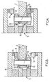
- FIGS. 1 and 2 illustrate an arm 1 carrying at one of its ends a common support shaft 2 on the end of which are mounted two rollers 3, 4 follower or idler rollers.
- the two rollers 3, 4 are substantially identical. In other embodiments, not shown, the rollers 3, 4 have different outer diameters, and / or different heights h, and / or different inner diameters Di.
- the two rollers 3, 4 are mounted at one end of the axis 2 towards the bottom of the figures, an assembly 5 defining a double pair of cams, generally gutter-shaped, having an opening 6 turned towards the top of figures 1 and 2 .
- an assembly 5 defining a double pair of cams, generally gutter-shaped, having an opening 6 turned towards the top of figures 1 and 2 .
- the device represented in figures 1 and 2 could be turned over, the opening of the assembly 5 being turned downwards, the axis 2 penetrating from below upwards in this assembly 5.
- the two rollers 3, 4 are spaced from one another by a spacer or a ring 7.
- the rigid assembly defining the double pair of Cams are rigid.
- rigid here is meant that the position of the cam paths 8, 9, 10, 11 in this set 5 is predetermined.
- the assembly 5 is formed of the assembly of sections 12, 13, 14, 15 carrying the cam paths 8, 9, 10, 11 and other intermediate sections 16, 17, 18, 19 and a base section 20, so that the assembly has a general shape of gutter, with a bottom wall, constituted by the base section 20, and two wings, each of the two wings supporting at least one of the cam paths (each of the two wings supports two cam paths in the illustrated examples).
- a first axis 2a is of such a length that the rollers 3a, 4a cooperate with the two lower cam paths 10, 11.
- a second axis 2b is of a length such that the rollers 3b, 4b cooperate with the two upper cam paths 8, 9.
- the rollers 3a, 4a, carried by the first axis 2a are substantially identical to the rollers 3b, 4b carried by the second axis 2b.
- the rollers 3b, 4b carried by the second axis 2b have external diameters Of different, and / or different heights h, and / or inner diameters Di different from those of the rollers 3a , 4a carried by the first axis 2a.
- a spacer 21 is mounted on the long axis 2a, between the upper roller 3a and an annular abutment 22. This spacer 21 is placed at a minimum clearance of the cam path that is closest thereto. As an indication this game is of the order of a millimeter.
- the arm 1 is rotatably mounted about an axis 23, substantially parallel to the axis of rotation 24 of the rollers. This axis of rotation 23 is at a fixed distance from the axis of rotation 24 of the rollers.
- the installation of the assembly 5 on the machine is carried out with the usual care to the fixing of a cam path on a machine (for example locating comparator, piontage).
- the assembly once placed on the machine, it is sufficient to change the support axes of rollers during the modification of the process, the short axis 2b which follows the cam paths 8, 9 corresponding to a first method, the long axis 2b following the cam paths 10, 11 corresponding to a second method independent of the first.
- the roller bearing shaft change does not require special adjustment and can be carried out quickly by relatively untrained personnel.
- This movable axis, with two positions, high and low, mounted on a fixed arm thus makes it possible to change the cam path used for the rollers, on the fixed assembly.
- the rigid assembly 5 is also formed by assembling elements of which only some define the cam paths.
- the assembly 5 forms a gutter with lateral opening 6, into which the arm 1 carrying the axis 2 supporting the rollers 3, 4 penetrates.
- the two rollers may be identical or not.
- the axis 2 can occupy two predetermined extreme positions.
- the axis 2 is movable and the assembly 5 is fixed.
- the axis 2 is fixed and the assembly 5 is movable.
- the relative displacement of the axis 2 and the assembly 5 is effected between two positions by up / down movement.
- the phrase "up / down" is here used in reference to the guidance given in Figures 3 and 4 and should not be seen as limiting.
- a first roller 3 cooperates with a first cam path 10.
- this first roller 3 cooperates with a second cam path 11.
- the device could, in one embodiment, have only this first roller 3 carried by the axis 2 and cooperating with one or other of the cam paths 10, 11.
- the axis 2 carries a second roller 4.
- the second roller 4 cooperates with a third cam path 9.
- This second roller 4 cooperates with a fourth cam path 8.
- the installation of the assembly 5 on the machine is carried out with the usual care to the fixing of a cam path on a machine (for example locating comparator, piontage).
- a machine for example locating comparator, piontage.
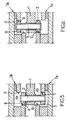
- two rigid sets 5a, 5b are each also formed by assembling elements of which only some define the cam paths.
- the advantages of this construction, exhibited in reference to the embodiment of figures 1 and 2 are still valid and are not repeated.
- each set 5a, 5b forms a gutter with openings 6a, 6b facing each other.
- each of these openings 6a, 6b penetrates an end portion of an arm 1 carrying the axis 2 supporting the rollers 3, 4.
- the two rollers may be identical or not.
- the axis 2 is movable and the sets 5a, 5b are fixed.
- the axis 2 is fixed and the sets 5a, 5b are movable. By relative displacement of the axis 2 and the sets 5a, 5b, the axis 2 can occupy two predetermined extreme positions, between these two positions by up / down movement.
- the expression “up / down” is used here in reference to the orientation given in Figures 5 and 6 and should not be seen as limiting.
- a first roller 3 In the first "high” position ( figure 6 ), a first roller 3 cooperates with a first cam path 10. In the second "low” position ( figure 5 ), this first roller 3 cooperates with a second cam path 11.
- the device could, in one embodiment, have only this first roller 3 carried by the axis 2 and cooperating with one or other of the cam paths 10, 11, only the assembly 5a carrying these two cam paths being present.
- the axis 2 carries a second roller 4. In the first "up” position ( figure 6 ), this second roller 4 cooperates with a third cam path 9. In the second "low” position ( figure 5 ), this second roller 4 cooperates with a fourth cam path 8.
- the implementation of the assemblies 5a, 5b on the machine is carried out with the usual care to the fixing of a cam path on a machine (for example locating to the comparator, pioneering). Once the sets have been placed on the machine, it suffices to make a relative displacement of the roller bearing pins 2 and subassemblies 5a, 5b during the modification of the method, the axis 2 following the cam paths 9, 10 corresponding to a first method, or according to the cam paths 8, 11 corresponding to a second method independent of the first. This relative movement does not require any particular adjustment and can be performed quickly by relatively untrained personnel, or be controlled by the operator.
- valve movement in particular for the opening and / or closing of the filling heads, or the control of the vertical movements of the filling heads, or the control of the vertical movements of the containers for machines. carousel type filling.
Landscapes
- Engineering & Computer Science (AREA)
- Mechanical Engineering (AREA)
- Manufacturing & Machinery (AREA)
- General Engineering & Computer Science (AREA)
- Blow-Moulding Or Thermoforming Of Plastics Or The Like (AREA)
- Transmission Devices (AREA)
- Filling Of Jars Or Cans And Processes For Cleaning And Sealing Jars (AREA)
- Basic Packing Technique (AREA)
- Moulds For Moulding Plastics Or The Like (AREA)
- Branching, Merging, And Special Transfer Between Conveyors (AREA)
- Sampling And Sample Adjustment (AREA)
- Control And Other Processes For Unpacking Of Materials (AREA)
- Electrical Discharge Machining, Electrochemical Machining, And Combined Machining (AREA)
- Finish Polishing, Edge Sharpening, And Grinding By Specific Grinding Devices (AREA)
Claims (11)
- Steuerungsvorrichtung durch Einsatz eines Folgeglieds und eines Nockenwegs für ein Maschinenelement zur Bearbeitung von Behältern, das zwei Nockenwege umfasst, die durch einen einzelnen starren Bausatz (5) ausgebildet werden, wobei Mittel die Gewährleistung einer relativen Bewegung zwischen dem Folgeglied und dem festen Bausatz (5) zwischen zumindest zwei Positionen ermöglichen, wobei das Folgeglied in einer ersten Position mit einem ersten Nockenweg wirkt, das Folgeglied in einer zweiten Position mit einem zweiten Nockenweg wirkt, dadurch gekennzeichnet, dass das Folgeglied zwei Rollen (3, 4) umfasst, die von einer gemeinsamen Trägerachse (2) getragen werden, wobei die erste und die zweite Rolle (3, 4) jeweils mit einem ersten und einem zweiten Nockenweg in einer ersten Position der gemeinsamen Trägerachse (2) in Bezug auf den starren Bausatz wirken und die erste und die zweite Rolle (3, 4) jeweils mit einem dritten und einem vierten Nockenweg in einer zweiten Position der Achse in Bezug zum starren Bausatz (5) wirken.
- Vorrichtung nach Anspruch 1, dadurch gekennzeichnet, dass der starre Bausatz (5), der die Nockenwege ausbildet, fest und die gemeinsame Trägerachse (2) mobil ist.
- Vorrichtung nach Anspruch 1, dadurch gekennzeichnet, dass der starre Bausatz (5) zur Ausbildung der Nockenwege mobil und die gemeinsame Trägerachse (2) fest ist.
- Vorrichtung nach einem der Ansprüche 1 bis 3, dadurch gekennzeichnet, dass der starre Bausatz (5) aus der Verbindung von Abschnitten (12-15), die die Nockenwege für das Folgeglied aufnehmen, und aus Zwischenabschnitten (16-19) ausgebildet ist.
- Vorrichtung nach einem der vorstehenden Ansprüche, dadurch gekennzeichnet, dass der starre Bausatz (5) eine allgemeine Rinnenform mit einer Bodenwand und zwei Flügeln aufweist, wobei die beiden Flügel jeweils zumindest einen Nockenweg aufnehmen.
- Vorrichtung nach einem der Ansprüche 1 bis 5, dadurch gekennzeichnet, dass sie zwei starre Bausätze (5a, 5b) umfasst, die jeweils eine Rinnenform aufweisen, wobei die Öffnungen (6a, 6b) dieser starren Bausätze zueinander gerichtet sind und die erste und die zweite Rolle jeweils mit einem Nockenweg jedes starren Elements in der ersten und in der zweiten Position wirkt.
- Vorrichtung nach einem der Ansprüche 1 bis 5, dadurch gekennzeichnet, dass der starre Bausatz (5) eine Rinnenform mit Seitenöffnung aufweist, wobei die Rollen auf eine Achse beidseitig von einem Arm (1) montiert sind, wobei dieser Arm mobil zwischen einer ersten Endstellung, in der sich der Arm (1) möglichst nah an einem ersten Seitenrand der Rinnenöffnung befindet, und einer zweiten Endstellung, in der sich der Arm möglichst nah an einem zweiten Seitenrand der Öffnung befindet, montiert ist.
- Vorrichtung nach einem der Ansprüche 1 bis 5, dadurch gekennzeichnet, dass der starre Bausatz (5) eine Rinnenform mit einer nahezu rechtwinkeligen Öffnung (6) zur Drehachse der Rollen aufweist, wobei die Rollenträgerachse (2, 3, 4) beweglich auf einem Trägerarm (1) montiert ist, wobei eine erste kurze Achse (2b) gewährleistet, dass die erste und die zweite Rolle jeweils mit einem ersten und einem zweiten Nockenweg des starren Bausatzes wirkt und eine zweite lange Achse gewährleistet, dass die erste und die zweite Rolle jeweils mit einem dritten und einem vierten Nockenweg des starren Bausatzes wirkt.
- Vorrichtung nach einem der vorstehenden Ansprüche, dadurch gekennzeichnet, dass das erste Folgeglied zwei oder mehr als zwei nahezu identische Rollen umfasst.
- Gebläse- und Streckgebläsemaschine, um thermoplastischen Behälter zu blasen oder strecken-blasen, die zumindest eine Vorrichtung nach einem der vorstehenden Ansprüche, insbesondere für die Bewegungssteuerung der Dehnungsstangen oder die Verriegelungs- und Entriegelungssteuerung der Formen oder die Öffnungs-/Schließsteuerung der Formen umfasst.
- Behälterfüllmaschine, die zumindest eine Vorrichtung nach einem der Ansprüche 1 bis 9, insbesondere für die Öffnungs- und/oder Schließsteuerung der Füllglieder oder die Steuerung der Bewegungen der Füllköpfe oder die Steuerung der Bewegungen der Behälter umfasst.
Applications Claiming Priority (2)
| Application Number | Priority Date | Filing Date | Title |
|---|---|---|---|
| FR0512862A FR2894867B1 (fr) | 2005-12-16 | 2005-12-16 | Dispositif de commande par organe suiveur et chemin de came d'un element de machine de traitement de recipients |
| PCT/FR2006/002742 WO2007080272A1 (fr) | 2005-12-16 | 2006-12-15 | Dispositif de commande par organe suiveur et chemin de came d'un element de machine de traitement de recipients et machine de traitement de recipients comprenant un tel dispositif |
Publications (2)
| Publication Number | Publication Date |
|---|---|
| EP1963075A1 EP1963075A1 (de) | 2008-09-03 |
| EP1963075B1 true EP1963075B1 (de) | 2009-02-18 |
Family
ID=36941961
Family Applications (1)
| Application Number | Title | Priority Date | Filing Date |
|---|---|---|---|
| EP06841945A Not-in-force EP1963075B1 (de) | 2005-12-16 | 2006-12-15 | Ein folgeglied und eine nockenbahn einsetzender steuervorrichtung für ein maschinenelement zur bearbeitung von behältern und solch eine vorrichtung umfassende behälterbearbeitungsmaschine |
Country Status (10)
| Country | Link |
|---|---|
| US (1) | US7922478B2 (de) |
| EP (1) | EP1963075B1 (de) |
| JP (1) | JP4814340B2 (de) |
| CN (1) | CN101374647B (de) |
| AT (1) | ATE422996T1 (de) |
| DE (1) | DE602006005267D1 (de) |
| ES (1) | ES2320808T3 (de) |
| FR (1) | FR2894867B1 (de) |
| PT (1) | PT1963075E (de) |
| WO (1) | WO2007080272A1 (de) |
Families Citing this family (4)
| Publication number | Priority date | Publication date | Assignee | Title |
|---|---|---|---|---|
| CN109843547B (zh) * | 2016-10-12 | 2021-08-10 | 日精Asb机械株式会社 | 吹塑成形模具 |
| JP7219982B1 (ja) | 2021-07-15 | 2023-02-09 | 俊行 秋山 | 共役カム装置 |
| DE102023104677A1 (de) * | 2023-02-27 | 2024-08-29 | Khs Gmbh | Blasanlage zum Umformen von Kunststoff-Vorformlingen |
| US20240359227A1 (en) * | 2023-04-28 | 2024-10-31 | Stolle Machinery Company, Llc | Reformer with 3-dimensional track groove cam assembly |
Family Cites Families (11)
| Publication number | Priority date | Publication date | Assignee | Title |
|---|---|---|---|---|
| JPS4738279U (de) * | 1971-05-24 | 1972-12-27 | ||
| US5195565A (en) * | 1991-10-11 | 1993-03-23 | Elopak Systems A.G. | Variable stroke lifter system |
| US5528879A (en) * | 1995-05-26 | 1996-06-25 | Diversified Capping Equipment, Inc. | Apparatus for applying closures to containers |
| JPH11201255A (ja) * | 1997-12-12 | 1999-07-27 | Molex Inc | 拘束直動カム装置における過負荷保護装置 |
| JP4335360B2 (ja) * | 1999-05-25 | 2009-09-30 | 株式会社日本製鋼所 | 溝カム作動機構 |
| FR2798093B1 (fr) * | 1999-09-03 | 2001-11-30 | Sidel Sa | Machine rotative d'etirage-soufflage comportant une commande magnetique de la tige d'etirage |
| FR2802191B1 (fr) * | 1999-12-13 | 2002-03-01 | Sidel Sa | Dispositif de convoyage d'entites discretes comportant un bras de transfert perfectionne et installation de soufflage de recipients munie d'un tel dispositif |
| DE20006524U1 (de) * | 2000-04-08 | 2000-06-29 | KRONES AG, 93073 Neutraubling | Streckblasmaschine |
| DE10110668B4 (de) * | 2001-03-06 | 2012-03-29 | Schaeffler Technologies Gmbh & Co. Kg | Kurvennuttrieb |
| FR2833330B1 (fr) * | 2001-12-12 | 2004-02-27 | Sidel Sa | Dispositif de guidage a came et installation de moulage en faisant application |
| DE10246685A1 (de) * | 2002-10-07 | 2004-04-29 | Sig Technology Ltd. | Vorrichtung zur Kurvensteuerung |
-
2005
- 2005-12-16 FR FR0512862A patent/FR2894867B1/fr not_active Expired - Fee Related
-
2006
- 2006-12-15 AT AT06841945T patent/ATE422996T1/de not_active IP Right Cessation
- 2006-12-15 EP EP06841945A patent/EP1963075B1/de not_active Not-in-force
- 2006-12-15 DE DE602006005267T patent/DE602006005267D1/de active Active
- 2006-12-15 ES ES06841945T patent/ES2320808T3/es active Active
- 2006-12-15 JP JP2008545043A patent/JP4814340B2/ja not_active Expired - Fee Related
- 2006-12-15 CN CN200680052990.7A patent/CN101374647B/zh not_active Expired - Fee Related
- 2006-12-15 US US12/097,357 patent/US7922478B2/en not_active Expired - Fee Related
- 2006-12-15 PT PT06841945T patent/PT1963075E/pt unknown
- 2006-12-15 WO PCT/FR2006/002742 patent/WO2007080272A1/fr not_active Ceased
Also Published As
| Publication number | Publication date |
|---|---|
| EP1963075A1 (de) | 2008-09-03 |
| JP4814340B2 (ja) | 2011-11-16 |
| DE602006005267D1 (de) | 2009-04-02 |
| CN101374647A (zh) | 2009-02-25 |
| CN101374647B (zh) | 2012-09-05 |
| ATE422996T1 (de) | 2009-03-15 |
| WO2007080272A1 (fr) | 2007-07-19 |
| JP2009519418A (ja) | 2009-05-14 |
| US7922478B2 (en) | 2011-04-12 |
| US20090011069A1 (en) | 2009-01-08 |
| PT1963075E (pt) | 2009-05-13 |
| FR2894867B1 (fr) | 2010-01-08 |
| ES2320808T3 (es) | 2009-05-28 |
| FR2894867A1 (fr) | 2007-06-22 |
Similar Documents
| Publication | Publication Date | Title |
|---|---|---|
| EP2139666B1 (de) | Transfervorrichtung und lineares gerät zur herstellung von behältern | |
| EP3057767B1 (de) | Formeinheit zur herstellung von behältern mit einem kompensationsgreifer | |
| FR2544655A1 (fr) | Procede et dispositif pour fabriquer des corps creux en une matiere plastique deformable | |
| CA2382398C (fr) | Machine rotative d'etirage-soufflage comportant une commande magnetique de la tige d'etirage | |
| FR2505249A1 (fr) | Machine et procede de fabrication, par moulage par soufflage, d'une bouteille en resine thermoplastique | |
| FR2765515A1 (fr) | Dispositif et procede de fabrication d'un objet en matiere plastique par soufflage | |
| EP1919689B1 (de) | Blasformstation für eine behälterstreck-/blasanlage und anlage mit einer derartigen anordnung | |
| EP3105034B1 (de) | Formeinheit zur herstellung von behältern aus vorformlingen aus kunststoffmaterial | |
| EP1963075B1 (de) | Ein folgeglied und eine nockenbahn einsetzender steuervorrichtung für ein maschinenelement zur bearbeitung von behältern und solch eine vorrichtung umfassende behälterbearbeitungsmaschine | |
| EP3587071B1 (de) | Formgusseinheit, die mit einem mobilen einsatz zur erstellung von boxen ausgestattet ist, der durch einen vom fluidkreislauf der boxen-erstellung abgeleiteten fluidkreislauf belüftet wird | |
| EP0000801B1 (de) | Verfahren zur Herstellung orientierter Hohlkörper | |
| FR2890589A1 (fr) | Unite de moulage de type lineaire pour une installation de fabrication de recipients. | |
| EP3131734B1 (de) | Giesseinheit mit formbodenbetätigungseinrichtung auf einer fixen halterung | |
| EP3181327A1 (de) | Giessformboden mit grossen auslassöffnungen für das formverfahren eines behälters | |
| FR2956610A1 (fr) | Procede et outillage pour le moulage de corps creux par injection-soufflage | |
| EP3173212B1 (de) | Verfahren zur steuerung einer spritzguss-einheit | |
| CH629699A5 (en) | Installation for manufacturing biaxially-oriented plastic articles and mandrel for the installation | |
| EP1779993B1 (de) | Vorrichtung sowie Verfahren zur Herstellung eines thermoplastischen Behälters durch Blasformen | |
| WO2023126366A1 (fr) | Dispositif de moulage, par soufflage ou étirage-soufflage, de récipients en matière thermoplastique | |
| FR2880834A1 (fr) | "dispositif et procede de thermoformage d'objets ayant une collerette de base, et objets ainsi obtenus | |
| FR3004985A1 (fr) | "procede de faconnage d'une preforme chaude par estampage et dispositif pour sa mise en oeuvre" | |
| FR3144541A1 (fr) | Dispositif de montage et/ou de démontage de nez de tournette et application à une unité de conditionnement thermique de préformes. | |
| WO2015004172A1 (fr) | Unité de moulage de récipients en matière thermoplastique comportant des moyens de compensation |
Legal Events
| Date | Code | Title | Description |
|---|---|---|---|
| PUAI | Public reference made under article 153(3) epc to a published international application that has entered the european phase |
Free format text: ORIGINAL CODE: 0009012 |
|
| 17P | Request for examination filed |
Effective date: 20080610 |
|
| AK | Designated contracting states |
Kind code of ref document: A1 Designated state(s): AT BE BG CH CY CZ DE DK EE ES FI FR GB GR HU IE IS IT LI LT LU LV MC NL PL PT RO SE SI SK TR |
|
| GRAP | Despatch of communication of intention to grant a patent |
Free format text: ORIGINAL CODE: EPIDOSNIGR1 |
|
| DAX | Request for extension of the european patent (deleted) | ||
| GRAS | Grant fee paid |
Free format text: ORIGINAL CODE: EPIDOSNIGR3 |
|
| GRAA | (expected) grant |
Free format text: ORIGINAL CODE: 0009210 |
|
| AK | Designated contracting states |
Kind code of ref document: B1 Designated state(s): AT BE BG CH CY CZ DE DK EE ES FI FR GB GR HU IE IS IT LI LT LU LV MC NL PL PT RO SE SI SK TR |
|
| REG | Reference to a national code |
Ref country code: GB Ref legal event code: FG4D Free format text: NOT ENGLISH |
|
| REG | Reference to a national code |
Ref country code: CH Ref legal event code: EP |
|
| REG | Reference to a national code |
Ref country code: IE Ref legal event code: FG4D Free format text: LANGUAGE OF EP DOCUMENT: FRENCH |
|
| REF | Corresponds to: |
Ref document number: 602006005267 Country of ref document: DE Date of ref document: 20090402 Kind code of ref document: P |
|
| REG | Reference to a national code |
Ref country code: PT Ref legal event code: SC4A Free format text: AVAILABILITY OF NATIONAL TRANSLATION Effective date: 20090507 |
|
| REG | Reference to a national code |
Ref country code: ES Ref legal event code: FG2A Ref document number: 2320808 Country of ref document: ES Kind code of ref document: T3 |
|
| PG25 | Lapsed in a contracting state [announced via postgrant information from national office to epo] |
Ref country code: FI Free format text: LAPSE BECAUSE OF FAILURE TO SUBMIT A TRANSLATION OF THE DESCRIPTION OR TO PAY THE FEE WITHIN THE PRESCRIBED TIME-LIMIT Effective date: 20090218 Ref country code: SI Free format text: LAPSE BECAUSE OF FAILURE TO SUBMIT A TRANSLATION OF THE DESCRIPTION OR TO PAY THE FEE WITHIN THE PRESCRIBED TIME-LIMIT Effective date: 20090218 Ref country code: LT Free format text: LAPSE BECAUSE OF FAILURE TO SUBMIT A TRANSLATION OF THE DESCRIPTION OR TO PAY THE FEE WITHIN THE PRESCRIBED TIME-LIMIT Effective date: 20090218 Ref country code: NL Free format text: LAPSE BECAUSE OF FAILURE TO SUBMIT A TRANSLATION OF THE DESCRIPTION OR TO PAY THE FEE WITHIN THE PRESCRIBED TIME-LIMIT Effective date: 20090218 |
|
| NLV1 | Nl: lapsed or annulled due to failure to fulfill the requirements of art. 29p and 29m of the patents act | ||
| PG25 | Lapsed in a contracting state [announced via postgrant information from national office to epo] |
Ref country code: SE Free format text: LAPSE BECAUSE OF FAILURE TO SUBMIT A TRANSLATION OF THE DESCRIPTION OR TO PAY THE FEE WITHIN THE PRESCRIBED TIME-LIMIT Effective date: 20090518 Ref country code: AT Free format text: LAPSE BECAUSE OF FAILURE TO SUBMIT A TRANSLATION OF THE DESCRIPTION OR TO PAY THE FEE WITHIN THE PRESCRIBED TIME-LIMIT Effective date: 20090218 Ref country code: IS Free format text: LAPSE BECAUSE OF FAILURE TO SUBMIT A TRANSLATION OF THE DESCRIPTION OR TO PAY THE FEE WITHIN THE PRESCRIBED TIME-LIMIT Effective date: 20090618 Ref country code: PL Free format text: LAPSE BECAUSE OF FAILURE TO SUBMIT A TRANSLATION OF THE DESCRIPTION OR TO PAY THE FEE WITHIN THE PRESCRIBED TIME-LIMIT Effective date: 20090218 Ref country code: LV Free format text: LAPSE BECAUSE OF FAILURE TO SUBMIT A TRANSLATION OF THE DESCRIPTION OR TO PAY THE FEE WITHIN THE PRESCRIBED TIME-LIMIT Effective date: 20090218 |
|
| REG | Reference to a national code |
Ref country code: IE Ref legal event code: FD4D |
|
| PG25 | Lapsed in a contracting state [announced via postgrant information from national office to epo] |
Ref country code: DK Free format text: LAPSE BECAUSE OF FAILURE TO SUBMIT A TRANSLATION OF THE DESCRIPTION OR TO PAY THE FEE WITHIN THE PRESCRIBED TIME-LIMIT Effective date: 20090218 Ref country code: CZ Free format text: LAPSE BECAUSE OF FAILURE TO SUBMIT A TRANSLATION OF THE DESCRIPTION OR TO PAY THE FEE WITHIN THE PRESCRIBED TIME-LIMIT Effective date: 20090218 Ref country code: IE Free format text: LAPSE BECAUSE OF FAILURE TO SUBMIT A TRANSLATION OF THE DESCRIPTION OR TO PAY THE FEE WITHIN THE PRESCRIBED TIME-LIMIT Effective date: 20090218 Ref country code: EE Free format text: LAPSE BECAUSE OF FAILURE TO SUBMIT A TRANSLATION OF THE DESCRIPTION OR TO PAY THE FEE WITHIN THE PRESCRIBED TIME-LIMIT Effective date: 20090218 |
|
| PG25 | Lapsed in a contracting state [announced via postgrant information from national office to epo] |
Ref country code: RO Free format text: LAPSE BECAUSE OF FAILURE TO SUBMIT A TRANSLATION OF THE DESCRIPTION OR TO PAY THE FEE WITHIN THE PRESCRIBED TIME-LIMIT Effective date: 20090218 Ref country code: SK Free format text: LAPSE BECAUSE OF FAILURE TO SUBMIT A TRANSLATION OF THE DESCRIPTION OR TO PAY THE FEE WITHIN THE PRESCRIBED TIME-LIMIT Effective date: 20090218 |
|
| PLBE | No opposition filed within time limit |
Free format text: ORIGINAL CODE: 0009261 |
|
| STAA | Information on the status of an ep patent application or granted ep patent |
Free format text: STATUS: NO OPPOSITION FILED WITHIN TIME LIMIT |
|
| 26N | No opposition filed |
Effective date: 20091119 |
|
| PG25 | Lapsed in a contracting state [announced via postgrant information from national office to epo] |
Ref country code: BG Free format text: LAPSE BECAUSE OF FAILURE TO SUBMIT A TRANSLATION OF THE DESCRIPTION OR TO PAY THE FEE WITHIN THE PRESCRIBED TIME-LIMIT Effective date: 20090518 |
|
| BERE | Be: lapsed |
Owner name: SIDEL PARTICIPATIONS Effective date: 20091231 |
|
| PG25 | Lapsed in a contracting state [announced via postgrant information from national office to epo] |
Ref country code: MC Free format text: LAPSE BECAUSE OF NON-PAYMENT OF DUE FEES Effective date: 20100701 |
|
| PG25 | Lapsed in a contracting state [announced via postgrant information from national office to epo] |
Ref country code: GR Free format text: LAPSE BECAUSE OF FAILURE TO SUBMIT A TRANSLATION OF THE DESCRIPTION OR TO PAY THE FEE WITHIN THE PRESCRIBED TIME-LIMIT Effective date: 20090519 Ref country code: BE Free format text: LAPSE BECAUSE OF NON-PAYMENT OF DUE FEES Effective date: 20091231 |
|
| PG25 | Lapsed in a contracting state [announced via postgrant information from national office to epo] |
Ref country code: LU Free format text: LAPSE BECAUSE OF NON-PAYMENT OF DUE FEES Effective date: 20091215 |
|
| PG25 | Lapsed in a contracting state [announced via postgrant information from national office to epo] |
Ref country code: HU Free format text: LAPSE BECAUSE OF FAILURE TO SUBMIT A TRANSLATION OF THE DESCRIPTION OR TO PAY THE FEE WITHIN THE PRESCRIBED TIME-LIMIT Effective date: 20090819 |
|
| REG | Reference to a national code |
Ref country code: CH Ref legal event code: PL |
|
| PG25 | Lapsed in a contracting state [announced via postgrant information from national office to epo] |
Ref country code: TR Free format text: LAPSE BECAUSE OF FAILURE TO SUBMIT A TRANSLATION OF THE DESCRIPTION OR TO PAY THE FEE WITHIN THE PRESCRIBED TIME-LIMIT Effective date: 20090218 |
|
| PG25 | Lapsed in a contracting state [announced via postgrant information from national office to epo] |
Ref country code: CY Free format text: LAPSE BECAUSE OF FAILURE TO SUBMIT A TRANSLATION OF THE DESCRIPTION OR TO PAY THE FEE WITHIN THE PRESCRIBED TIME-LIMIT Effective date: 20090218 |
|
| PG25 | Lapsed in a contracting state [announced via postgrant information from national office to epo] |
Ref country code: LI Free format text: LAPSE BECAUSE OF NON-PAYMENT OF DUE FEES Effective date: 20101231 Ref country code: CH Free format text: LAPSE BECAUSE OF NON-PAYMENT OF DUE FEES Effective date: 20101231 |
|
| PGFP | Annual fee paid to national office [announced via postgrant information from national office to epo] |
Ref country code: PT Payment date: 20141203 Year of fee payment: 9 |
|
| REG | Reference to a national code |
Ref country code: FR Ref legal event code: PLFP Year of fee payment: 10 |
|
| PGFP | Annual fee paid to national office [announced via postgrant information from national office to epo] |
Ref country code: GB Payment date: 20151125 Year of fee payment: 10 |
|
| PGFP | Annual fee paid to national office [announced via postgrant information from national office to epo] |
Ref country code: ES Payment date: 20151204 Year of fee payment: 10 |
|
| REG | Reference to a national code |
Ref country code: PT Ref legal event code: MM4A Free format text: LAPSE DUE TO NON-PAYMENT OF FEES Effective date: 20160615 |
|
| PG25 | Lapsed in a contracting state [announced via postgrant information from national office to epo] |
Ref country code: PT Free format text: LAPSE BECAUSE OF NON-PAYMENT OF DUE FEES Effective date: 20160615 |
|
| REG | Reference to a national code |
Ref country code: FR Ref legal event code: PLFP Year of fee payment: 11 |
|
| PGFP | Annual fee paid to national office [announced via postgrant information from national office to epo] |
Ref country code: DE Payment date: 20161121 Year of fee payment: 11 Ref country code: FR Payment date: 20161121 Year of fee payment: 11 |
|
| PGFP | Annual fee paid to national office [announced via postgrant information from national office to epo] |
Ref country code: IT Payment date: 20161125 Year of fee payment: 11 |
|
| GBPC | Gb: european patent ceased through non-payment of renewal fee |
Effective date: 20161215 |
|
| PG25 | Lapsed in a contracting state [announced via postgrant information from national office to epo] |
Ref country code: GB Free format text: LAPSE BECAUSE OF NON-PAYMENT OF DUE FEES Effective date: 20161215 |
|
| PG25 | Lapsed in a contracting state [announced via postgrant information from national office to epo] |
Ref country code: ES Free format text: LAPSE BECAUSE OF NON-PAYMENT OF DUE FEES Effective date: 20161216 |
|
| REG | Reference to a national code |
Ref country code: DE Ref legal event code: R119 Ref document number: 602006005267 Country of ref document: DE |
|
| REG | Reference to a national code |
Ref country code: FR Ref legal event code: ST Effective date: 20180831 |
|
| PG25 | Lapsed in a contracting state [announced via postgrant information from national office to epo] |
Ref country code: DE Free format text: LAPSE BECAUSE OF NON-PAYMENT OF DUE FEES Effective date: 20180703 Ref country code: FR Free format text: LAPSE BECAUSE OF NON-PAYMENT OF DUE FEES Effective date: 20180102 Ref country code: IT Free format text: LAPSE BECAUSE OF NON-PAYMENT OF DUE FEES Effective date: 20171215 |
|
| REG | Reference to a national code |
Ref country code: ES Ref legal event code: FD2A Effective date: 20181120 |