EP1960825B1 - Verfahrn zur bestimmung eines satzes progressiver multifokal-brillengläser - Google Patents
Verfahrn zur bestimmung eines satzes progressiver multifokal-brillengläser Download PDFInfo
- Publication number
- EP1960825B1 EP1960825B1 EP06841912.6A EP06841912A EP1960825B1 EP 1960825 B1 EP1960825 B1 EP 1960825B1 EP 06841912 A EP06841912 A EP 06841912A EP 1960825 B1 EP1960825 B1 EP 1960825B1
- Authority
- EP
- European Patent Office
- Prior art keywords
- wearer
- gaze
- add
- lens
- vision
- Prior art date
- Legal status (The legal status is an assumption and is not a legal conclusion. Google has not performed a legal analysis and makes no representation as to the accuracy of the status listed.)
- Active
Links
- 230000000750 progressive effect Effects 0.000 title claims description 43
- 238000000034 method Methods 0.000 title claims description 25
- 201000009310 astigmatism Diseases 0.000 claims description 56
- 230000007547 defect Effects 0.000 claims description 28
- 238000009826 distribution Methods 0.000 claims description 28
- 238000005457 optimization Methods 0.000 claims description 15
- 230000002051 biphasic effect Effects 0.000 claims description 2
- 238000007493 shaping process Methods 0.000 claims description 2
- 239000011521 glass Substances 0.000 claims 1
- 210000001508 eye Anatomy 0.000 description 60
- 208000001491 myopia Diseases 0.000 description 56
- 230000004438 eyesight Effects 0.000 description 52
- 210000003128 head Anatomy 0.000 description 49
- 230000003287 optical effect Effects 0.000 description 17
- 239000000969 carrier Substances 0.000 description 13
- 230000004308 accommodation Effects 0.000 description 9
- 230000006870 function Effects 0.000 description 9
- 230000000007 visual effect Effects 0.000 description 9
- 238000004364 calculation method Methods 0.000 description 7
- 238000010586 diagram Methods 0.000 description 6
- 238000005259 measurement Methods 0.000 description 5
- 238000003754 machining Methods 0.000 description 4
- 241000697035 Heteropriacanthus cruentatus Species 0.000 description 3
- 238000013461 design Methods 0.000 description 3
- 230000000694 effects Effects 0.000 description 3
- 208000029091 Refraction disease Diseases 0.000 description 2
- 230000004075 alteration Effects 0.000 description 2
- 238000012937 correction Methods 0.000 description 2
- 230000007423 decrease Effects 0.000 description 2
- 230000001419 dependent effect Effects 0.000 description 2
- 230000008034 disappearance Effects 0.000 description 2
- 210000000887 face Anatomy 0.000 description 2
- 208000014733 refractive error Diseases 0.000 description 2
- IYLGZMTXKJYONK-ACLXAEORSA-N (12s,15r)-15-hydroxy-11,16-dioxo-15,20-dihydrosenecionan-12-yl acetate Chemical compound O1C(=O)[C@](CC)(O)C[C@@H](C)[C@](C)(OC(C)=O)C(=O)OCC2=CCN3[C@H]2[C@H]1CC3 IYLGZMTXKJYONK-ACLXAEORSA-N 0.000 description 1
- 206010020675 Hypermetropia Diseases 0.000 description 1
- 238000007476 Maximum Likelihood Methods 0.000 description 1
- 230000004430 ametropia Effects 0.000 description 1
- 230000003542 behavioural effect Effects 0.000 description 1
- 210000005252 bulbus oculi Anatomy 0.000 description 1
- 230000000295 complement effect Effects 0.000 description 1
- 210000005069 ears Anatomy 0.000 description 1
- 230000003028 elevating effect Effects 0.000 description 1
- 230000004424 eye movement Effects 0.000 description 1
- 238000004519 manufacturing process Methods 0.000 description 1
- 239000000463 material Substances 0.000 description 1
- 230000004048 modification Effects 0.000 description 1
- 238000012986 modification Methods 0.000 description 1
- 230000000877 morphologic effect Effects 0.000 description 1
- 230000003387 muscular Effects 0.000 description 1
- 230000008447 perception Effects 0.000 description 1
- 230000002093 peripheral effect Effects 0.000 description 1
- 230000001144 postural effect Effects 0.000 description 1
- 201000010041 presbyopia Diseases 0.000 description 1
- 230000008569 process Effects 0.000 description 1
- 210000001747 pupil Anatomy 0.000 description 1
- 230000001179 pupillary effect Effects 0.000 description 1
- IYLGZMTXKJYONK-UHFFFAOYSA-N ruwenine Natural products O1C(=O)C(CC)(O)CC(C)C(C)(OC(C)=O)C(=O)OCC2=CCN3C2C1CC3 IYLGZMTXKJYONK-UHFFFAOYSA-N 0.000 description 1
- 210000003462 vein Anatomy 0.000 description 1
Images


Classifications
-
- G—PHYSICS
- G02—OPTICS
- G02C—SPECTACLES; SUNGLASSES OR GOGGLES INSOFAR AS THEY HAVE THE SAME FEATURES AS SPECTACLES; CONTACT LENSES
- G02C7/00—Optical parts
- G02C7/02—Lenses; Lens systems ; Methods of designing lenses
- G02C7/06—Lenses; Lens systems ; Methods of designing lenses bifocal; multifocal ; progressive
- G02C7/061—Spectacle lenses with progressively varying focal power
- G02C7/063—Shape of the progressive surface
- G02C7/066—Shape, location or size of the viewing zones
-
- G—PHYSICS
- G02—OPTICS
- G02C—SPECTACLES; SUNGLASSES OR GOGGLES INSOFAR AS THEY HAVE THE SAME FEATURES AS SPECTACLES; CONTACT LENSES
- G02C7/00—Optical parts
- G02C7/02—Lenses; Lens systems ; Methods of designing lenses
- G02C7/024—Methods of designing ophthalmic lenses
- G02C7/025—Methods of designing ophthalmic lenses considering parameters of the viewed object
Definitions
- the present invention relates to a method for determining a set of progressive multifocal ophthalmic lenses and the lens set thus obtained; especially a progressive lens game customized to the specific needs of a given wearer.
- Any ophthalmic lens intended to be carried in a frame, is associated with a prescription.
- the ophthalmic prescription may include a positive or negative power prescription and a prescription for astigmatism. These prescriptions correspond to corrections to be made to the wearer of the lenses to correct the defects of his vision.
- a lens is mounted in the frame according to the prescription and the position of the wearer's eyes relative to the frame.
- the value of the power correction is different in far vision and in near vision, because of the difficulties of accommodation in near vision.
- the prescription is then composed of a power value in far vision and an addition (or progression of power) representative of the power increment between distant vision and near vision; this amounts to a far-sighted power prescription and a close-vision power prescription.
- Lenses adapted to presbyopic carriers are progressive multifocal lenses; these lenses are described by examples in FR-A-2,699,294 , US-A-5,270,745 or US-A-5,272,495 , FR-A-2,683,642 , FR-A-2,699,294 or. FR-A-2,704,327 .
- Progressive multifocal ophthalmic lenses include a far vision zone, a near vision zone, an intermediate vision zone, a main progression meridian crossing these three zones. They are generally determined by optimization, based on a number of constraints imposed on the different characteristics of the lens. Most commercialized lenses are general-purpose, in that they are adapted to the different common needs of wearers.
- each lens of a family being characterized by an addition, which corresponds to the power variation between the far vision zone and the near vision zone. More precisely, the addition, denoted A, corresponds to the power variation between a point VL of the far vision zone and a point VP of the near vision zone, which are respectively called the control point of the vision of distance and control point of the near vision, and which represent the points of intersection of the gaze and the surface of the lens for an infinite vision and for a vision of reading.
- a lens also conventionally presents a mounting cross CM. This is a point that is materialized on the surface of the lens and is used by the optician for mounting of the lens in the mount.
- the mounting cross CM corresponds to the point of intersection of the front face of the lens with the primary direction of the wearer's gaze.
- a progress length LP is also defined as the vertical distance between the mounting cross CM, and a point on the meridian on which the power progression reaches the power A.
- the progression length LP defines the accessibility to the necessary powers in near vision.
- Lenses of the same addition differ in the value of the average sphere in a reference point, also called base.
- the base of a lens is related to the curvature of a face of the lens and is given by the expression (n-1) / R where n is the refractive index and R the radius of curvature expressed in meters; the average power depends on the curvature of the other side of the lens.
- n is the refractive index and R the radius of curvature expressed in meters
- the average power depends on the curvature of the other side of the lens.
- a set or set of aspheric front faces for progressive multifocal lenses is thus defined by the choice of a pair (addition, base).
- an optimization is performed for a powerful data. This known method allows, from semi-finished lenses, of which only one face is shaped, to prepare lenses adapted to most
- the progressive multifocal lenses usually comprise a complex aspherical face, which may be the front face opposite to the wearer of the spectacles, and a spherical or toric surface, which may be the rear face directed towards the wearer of the spectacles.
- This spherical or toric surface makes it possible to adapt the lens to the ametropia of the user, so that a progressive multifocal lens is generally defined only by its complex aspherical surface.
- an aspherical surface is generally defined by the altitude of all its points. We also use the parameters constituted by the minimum and maximum curvatures at each point, or more commonly their half-sum and their difference.
- a progressive multifocal lens can thus be defined, at any point on its complex surface, by geometric characteristics including a mean sphere value and a cylinder value.
- the complex surface of the lens may be located on the front face or on the rear face or distributed between the two faces, according to the machining techniques used.
- a progressive multifocal lens can also be defined by optical characteristics taking into account the situation of the wearer of the lenses.
- the laws of the optics of the ray tracings lead to the appearance of optical defects when the rays deviate from the central axis of any lens.
- the document WO-A-98 12590 discloses a method for optimally determining a set of progressive multifocal ophthalmic lenses.
- This document proposes to define the set of lenses by considering the optical characteristics of the lenses and in particular the carrier power and the oblique astigmatism, under the conditions of the wearing:
- the lens is optimized by ray tracing, from an ergorama associating with each direction of the gaze in the conditions of the carried a target object point.
- EP-A-0 990 939 also proposes to determine a lens by optimization taking into account the optical characteristics and not surface of the lens.
- the characteristics of an average wearer are considered, particularly as regards the position of the lens in front of the wearer's eye in terms of curvature, pantoscopic angle and glass-eye distance.
- VARILUX IPSEO a range of progressive multifocal lenses, which are defined according to the behavior eye-head of the wearer. This definition is based on the observation that any wearer, to look at different points at a given height in the object space, can move either the head or the eyes and that the vision strategy of a wearer is based on a combination of the movements of the head and eyes.
- the wearer's vision strategy influences the perceived width of the fields on the lens.
- the more the lateral vision strategy of the wearer involves a movement of the head the less the area of the lens swept by the gaze of the wearer is wide.
- VARILUX IPSEO therefore proposes different lenses for the same ametropia-addition pair, depending on the carrier's lateral vision strategy.
- the company RUPP & HUBRACH also proposed, under the reference Ysis, to measure the inclination of the head during a task of near vision to determine the choice between four lengths of progression proposed.
- this measure does not fully take into account the eye-head behavior because it does not take into account the total lowering of the gaze, which can be defined as the sum of the lowering of the eyes in the orbits and the inclination of the eye. head.
- the invention accordingly proposes a method for optimally determining a set of progressive multifocal ophthalmic lenses from weighted targets in carrier power and resulting astigmatism; these targets being determined from the set of physiological parameters of the wearer and from a physio-optometric model.
- the physio-optometric model used in the context of the invention makes it possible to take into account all or some of the individual physiological parameters among the five previously identified and possibly to fix the others to standard default values. The wearer will thus be able to maintain a more natural posture while preserving his visual comfort.
- the invention more particularly proposes a method of determination by optimization of a set of progressive ophthalmic lenses according to claim 1.
- Add n is the nominal addition prescribed to the bearer; and k, b, alpha0 and sigma constants determined according to the physiological parameters of the wearer.
- the physiological parameters of the wearer measured are at least the vertical and horizontal participation coefficients of the near-vision head, the near-vision vertical horopter and the near-vision near-vision distance Dvp.
- the invention provides a method for determining a pair of progressive ophthalmic lenses for a presbyopic wearer, i.e., for whom power addition A has been prescribed for near vision.
- the figure 1 shows a diagram of an optical system eye and lens in side view, and shows the definitions used in the following description.
- Q the center of rotation of the eye
- the axis Q'F 'shown in the figure in phantom is the horizontal axis passing through the center of rotation of the eye and extending in front of the wearer - in other words the axis Q'F' corresponds to the direction Primary look.
- This axis cuts, on the front face, a point of the lens called CM Mounting Cross, which is materialized on the lenses to allow their positioning by an optician.
- the Montage Cross allows you to spot on the lens the primary direction of gaze under the conditions of the worn.
- Let the point O point of intersection of the rear face and this axis Q'F '.
- a value of the radius q 'of 27 mm corresponds to a current value and provides satisfactory results when wearing lenses.
- the section of the lens can be drawn in the plane (O, x, y) defined with reference to the figure 2 .
- the tangent to this curve at the point O is inclined relative to the axis (O, y) of an angle called the pantoscopic angle.
- the value of the pantoscopic angle is commonly 8 °.
- the tangent to this curve at the point O is inclined relative to the axis (O, z) of an angle called curve.
- the value of the curve is commonly 0 °.
- a given direction of gaze - represented in solid lines on the figure 1 corresponds to a position of the eye in rotation around Q 'and at a point J of the sphere of the vertices; a direction of gaze can also be spherical coordinates, identified by two angles ⁇ and ⁇ .
- the angle ⁇ is the angle formed between the axis Q'F 'and the projection of the line Q'J on the horizontal plane containing the axis Q'F'; this angle appears on the diagram of the figure 1 .
- the angle ⁇ is the angle formed between the axis Q'F 'and the projection of the line Q'J on the vertical plane containing the axis Q'F'.
- a given direction of gaze thus corresponds to a point J of the sphere of vertices or to a pair ( ⁇ , ⁇ ).
- the image of a point M of the object space situated at a given object distance is formed between two points S and T corresponding to distances JS and JT minimum and maximum (which would be distances sagittal and tangential focal in the case of surfaces of revolution, and a point M to infinity).
- the angle ⁇ identified as the axis of astigmatism, is the angle formed by the image corresponding to the smallest distance with the axis (z m ), in the plane (z m , y m ) defined with reference to Figures 2 and 3 .
- the angle ⁇ is measured in the direct trigonometric direction when looking at the wearer.
- the image of a point of the object space at infinity is formed at the point F'; the points S and T coincide, which is to say that the lens is locally spherical in the primary direction of gaze.
- the distance D is the front end of the lens.
- the Figures 2 and 3 show perspective diagrams of an eye-lens system.
- the points J and O are then merged.
- the figure 3 shows the position of the eye and the reference that is linked to it in a direction ( ⁇ , ⁇ ).
- the reference ⁇ x, y, z ⁇ originates from the point Q '; the axis x is the axis Q'F '- the point F' not being represented on the Figures 2 and 3 and goes through the point O; this axis is oriented from the lens to the eye, in correspondence with the measurement direction of the axis of astigmatism.
- the plane ⁇ y, z ⁇ is the vertical plane; the y axis is vertical and upward; the z axis is horizontal, the reference being orthonormed direct.
- the law of Listing gives the relations between the marks ⁇ x, y, z ⁇ and ⁇ x m , y m , z m ⁇ for each direction of the gaze, see Legrand, Physiological Optics, Volume 1, Edition of the Revue d'Optique, Paris 1965 .
- the angle of astigmatism is the angle ⁇ defined above: it is the angle measured in a reference linked to the eye, with respect to the direction z m , with which the image T is formed. , in the plane (z m , y m ).
- These definitions of power and astigmatism are optical definitions, in the conditions of wear and in a frame related to the eye
- the power and the astigmatism thus defined correspond to the characteristics of a thin lens, which placed at the place of the lens in the direction of the gaze, would provide locally the same images.
- the definition provides, in the primary direction of gaze, the classic value of prescription of astigmatism.
- Such a prescription is made by the ophthalmologist, in far vision, in the form of a pair formed of an axis value (in degrees) and an amplitude value (in diopters).
- the power and astigmatism thus defined can be measured experimentally on the lens using a frontofocometer; they can also be calculated by ray tracing in the conditions of the worn.
- the resulting astigmatism is a defect inherent to progressive lenses; it can therefore be considered as a tolerable defect, at least in the peripheral zone of the lens.
- the present invention proposes to take into account the physiological parameters of a given wearer, such as the participation of the head in horizontal and vertical, the privileged lowering of the gaze during a task of near vision, the privileged distance of working in close vision and the lateral shift of the document in close vision, to design progressive lenses specific to each individual so that he can fully enjoy the compensation of his presbyopia effortlessly in a natural posture and preserving its visual comfort.
- the taking into account of such individual parameters is today possible industrially thanks to the direct machining methods of the complex surfaces constituting the progressive lenses.
- the invention proposes to use the physiological parameters of the wearer to limit as much as possible the resulting astigmatism in the gaze field most used by this wearer.
- the less a gaze orientation is used the more the defect of tolerable astigmatism can be important.
- a set of progressive ophthalmic lenses having a resulting astigmatism defect controlled as a function of the frequency of the gaze orientations through the lenses can thus be obtained.
- each individual adopts a posture to have maximum visual comfort in near vision.
- the individual adopts a posture allowing to have a distance of sight close to a preferred value and inclines his document or modifies the elevation of the eyes and the head if the document is placed on a support, so the coincide with its vertical horopter.
- the vertical horopter for a given fixation point is defined here as the place of vertical lines perceived binocularly simple and vertical.
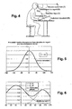
- the figure 4 schematically illustrates a carrier in a reading environment of a document, that is to say in which the near vision of the wearer is solicited.
- the applicant's experimental observations have shown that to explore his environment an individual moves more or less the head and the eyes through coordinated movements.
- the movements of the head are characterized in a reference linked to the space originating from the center of rotation of the head.
- the movements of the eyes are characterized in markings related to the head and originating from the center of rotation of each of the two eyes.
- the direction of gaze D R is characterized with respect to a reference plane linked to the head and called Frankfurt plane.
- a definition of the Frankfurt plan is given in the patent applications FR-A-2,683,642 and FR-A-2,683,643 ;
- the plane of Frankfurt PF is the plane passing through the lower edge of eye orbits and by the tragedy of the wearer's ears.
- the direction of view D R is a line belonging to a plane containing the target point and the centers of rotation of the eyes.
- the wearer When the wearer leaves a viewing point in far vision to reach a near vision point of view, it is positioned so that the average distance of the document in his eyes is close to its preferred distance Dvp; and it inclines the document and / or lowers the eyes and the head in respective proportions according to the individuals so that the document makes an angle close to its vertical horopter with the direction of the gaze.
- the elevation of the head is defined as the angle T made by the plane of Frankfurt PF with a horizontal plane of space and the elevation of the eyes - or the elevation of the eye - is defined as the angle Y that makes the direction of the look D R with the plane of Frankfurt P F.
- the elevation values of the eyes or the head are therefore lowering and are expressed with negative angle values.
- the lowering of the gaze R is thus the angle formed between the horizontal plane of the space and the direction of the gaze D R.
- the vertical horopter In the vicinity of the point of attachment, the vertical horopter can be likened to a plane portion more or less inclined by an angle H with respect to the viewing direction D R. Because of the muscular balance, the lowering of the eyes in close vision associated with the convergence causes a torsion of the eyeballs which induces a modification of the vertical and horizontal references of the visual system.
- the vertical horopter H therefore varies with the elevation of the eyes Y.
- the vertical horopter H for a given subject, varies with the aiming distance. Reference can be made to this subject in the manual "Vergence eye movements: Basic & clinical aspects" by Clifton M. Schor and Kenneth J. Ciuffreda, p 557, published in 1983.
- the vertical horopter is a size that varies from one individual to another according to morphological, physiological and behavioral parameters; on the other hand, the vertical horopter, for a given distance, is substantially constant for a given individual.
- each individual will position and / or incline his document by an angle B so that the document makes an angle close to its vertical horopter with the direction of the gaze D R.
- the near vision distance preferred Dvp varies from one individual to another but remains substantially constant for a given individual.
- the physiological parameters of the carrier it will be considered that the document is placed flat on a horizontal support, that is to say that the angle B is zero.
- the vertical horopter H and the direction of gaze will therefore have the same angular value.
- the method of the invention proposes to measure by appropriate means the vision posture of nearly each carrier.
- the method proposes to limit as much as possible the resulting astigmatism in the field of view most used by the wearer.
- the personalization parameters thus make it possible not only to provide a set of progressive ophthalmic lenses having a progression length specifically adapted to the wearer, but also to provide a set of progressive ophthalmic lenses having a frequency-controlled astigmatism defect as a function of the frequency. orientations of the gaze through the lenses.
- a physio-optometric model is constructed whose input variables are the physiological parameters of the wearer. This model will thus provide target values for the optimization of the complex surfaces of each lens of the personalized lens set according to the distribution of the gaze orientations of the wearer.
- the figure 5 is a graph showing the distribution of the horizontal orientations of the gaze.
- the maximum probability is obtained for the maximum frequency. We can normalize this probability of occurrence by reducing this maximum probability to 1.
- the figure 5 shows that the horizontal orientation of the highest gaze corresponds to a straight look ahead and that the horizontal deflection of the gaze decreases with the lowering of gaze.
- the figure 6 is a graph showing the distribution of the vertical orientations of the gaze.
- the vertical scanning frequency may be represented by the envelope of at least two Gaussians; one for far vision G_VL and one for near vision G_VP.
- the figure 6 gives an example of distribution of the lowering of the gaze with a horizontal deflection null.
- the maximum Gaussian distribution for near vision is focused on lowering the preferred gaze to near vision for each subject.
- the maximum of Gaussian distribution for far vision is centered in the vicinity of the straight ahead direction. It can be considered that far vision is generally used more than near vision.
- a coefficient can therefore modulate the Gaussian of the distribution in near vision; in the example of the figure 6 , this coefficient is fixed at 0.75, that is to say that the relative probability of a lowering of the gaze on the vertical horopter in near vision is less important than the relative probability of a straight look ahead.
- the resultant power and astigmatism defect tolerable at a given point will then be a function of the value of the Gaussian horizontal distribution and standard deviation of the horizontal orientation of the gaze as represented on the figure 5 .
- the astigmatism defect will be set to a null value when GaussH is equal to 1 and can reach a maximum value when GaussH is zero.
- the ideal lens would have no astigmatism defect. We must therefore fix for each point of a lens a tolerable defect.
- the model sets this maximum probability on the sagittal plane and therefore on the meridian.
- the constants a and kp are set to 2 so that the maximum power failure P is 0.5 diopters for a nominal addition Add n of 2 diopters and zero when Add r is equal to Add n / 2.
- the figure 7b shows that the application equation (2) in the optical optimization calculation process does not correspond to achievable targets for progressive multifocal lenses. Indeed, on the figure 7a , the fields close too much at the top and bottom of the lens to be able to control the distribution of defects on the surface in far vision zone and near vision zone.
- the small distance between the maxima of the vertical distributions of the lowering (or elevation) of the gaze causes the disappearance of the hollow between the isoastigmatism curves in far vision and in near vision on global distribution. This disappearance of the hollow is incompatible with the optimization of progressive lenses where the width between the isoastigmatism lines is essentially controlled by the speed of variation of the power along the meridian.
- the figure 8 shows the distribution of vertical ocular orientations for a zero horizontal deflection.
- the figure 8 is a graphical representation of equation (5) of ⁇ h with Elev OC as abscissa.
- the graph of the figure 8 therefore represents the standard deviations of eye orientation in the sagittal plane.
- the specificity of the progressive lenses is taken into account by varying the value of the maximum astigmatism (Ast MAX ) according to the elevation of the gaze in order to better control the values. Tolerable astigmatism in near vision and far vision areas.
- This equation (9) of the maximum tolerable astigmatism on the lens depends not only on the nominal addition Add n but also on the elevation of the gaze. The maximum value of astigmatism resulting will therefore be reached on the part of the lens around the pinch defined on the figure 8 .
- the figure 9 gives a graphic representation of Ast MAX according to the elevation of the gaze.
- the factor (k + b) sets the maximum value of astigmatism as a function of addition for a gaze elevation minus 121 °. This maximum value of astigmatism is set to Add n . (K + b) .1,25 and the minimum value is Add n . (K + b) .0,25.
- the value of 121 ° is chosen to allow validity of the expression throughout the visual field (120 ° upwards).
- the resulting power and astigmatism defect equations (7) and (8) allow the optimization of the design of a progressive lens.
- a set of progressive lenses customized to the needs of a wearer can be calculated with the above equations by introducing the physiological parameters of the wearer in the calculation of the ergorama and by varying some of the factors of said equations according to the carrier parameters for to work towards feasible design solutions.
- the method according to the invention thus proposes to measure the vertical horopter in near vision H of the wearer, that is to say the angle that the direction of gaze with the document containing the target point, as well as the lowering the gaze and elevating the head in near vision and determining a vertical participation coefficient Ptv of the head in near vision in order to determine a progression length LP specifically adapted to the needs of this wearer.
- the method also proposes to determine the preferred near-Dvp vision distance of the wearer, as well as the roll of the head and the horizontal coefficient of participation of the head Pth.
- the coefficient of horizontal participation of the head is defined as the ratio of the orientation of the head in the horizontal plane to the orientation of the gaze in this same plane.
- the chosen environment is an office environment as represented on the figure 4 .
- the carrier is positioned in such a way that to fix the center of the document he lowers the eyes and the head so that the angle that the document makes with the line of sight D R is equal to the vertical horopter H in near vision and that the document is at a near-miss distance Dvp of his eyes.
- This positioning makes it possible to place the center of rotation of the head in the environment. This point is then considered fixed.
- the wearer's head will turn around this point, eyes will turn in the head.
- the position of the centers of ocular rotation with respect to the center of rotation of the head is known, the lowering of the eyes which is the complement to have the vertical horopter in near vision is deduced.
- the ergorama makes it possible to link this accommodation to the convergence necessary to merge with the two eyes the point of near vision, taking into account the prismatic effects of the lenses.
- the ergorama defines the relationship of accommodation on convergence.
- the subject Once the subject is positioned in his environment, he sweeps it in a predetermined angular and square mesh, by coordinated movements of the eyes and the head in a physiological reference mark (elevation, azimuth). This coordination of movements respects the coefficients of horizontal and vertical participation of the head characterizing the subject. Knowing the position of each node of the mesh with respect to the center of rotation of the head, the required power and the position of the points of impact on the lenses (taking into account the prismatic effects due to this power) are calculated from the accommodation / convergence link characterizing the subject. Such a calculation is done by nested iterations, ie a loop of iterations following the horizontal for each step of the loop of iterations following the vertical. These iterations are used to merge the two eyes on the treated point of space by seeking to cancel the pointing error for each eye by small successive changes in the position of the eyes - accommodation.
- a physiological reference mark elevation, azimuth
- the present invention therefore proposes to measure the posture in close vision by appropriate equipment allowing, among other things, the measurement of the closest near vision distance, the lowering of the preferred gaze in near vision and at least the preferred elevation of the head or preferred elevation of the eyes in near vision.
- Such equipment may include a sensor placed on the wearer's head and an element for locating the target point, such as a sensor placed on a pointer pen or any device for measuring the rotation of the eyes in their mark.
- the constants of the various relations above are determined from the physiological parameters of the wearer.
- the personal physiological parameters of the wearer namely his vertical participation coefficients Pth and horizontal Ptv of the near-vision head, as well as his vertical horopter H in close vision and his near vision distance Dvp are taken into account. calculating target values of the resulting power and astigmatism defect to determine a lens set specifically adapted to that wearer.
- These personalization values are added to the values of curvature, pantoscopic angle, pupillary distance, glass-eye distance and pupil length and height of each eye. All these parameters inform the calculation program by optical optimization to calculate the pair of lenses by successive iterations.
- the tolerated power failure is introduced in the calculation of the prismatic deviations, therefore in the calculation of accommodation and convergence.
- the tolerated astigmatism defect is calculated for each node of the mesh once the horizontal and vertical iterations have converged on the null pointing error of equation (9) of the model which depends on the characteristics of the wearer.
- a weight dependent on the position of the point of impact on the lens is assigned to the calculated power.
- a weight, dependent on the position of the point of impact on the lens and the value of ProbH 'given by equation (4) and the characteristics of the wearer, is assigned to the tolerable astigmatism defect which becomes the resulting astigmatism .
- the weights along the meridian and in more or less large areas around the control points VL and VP are set at values much higher than the others.
- a weight between 15 and 10 is assigned to the carrier power on the meridian and points VP and VL while all other weights are set to 1; and a weight between 12 and 8 is attributed to the astigmatism on the meridian and points VP and VL while the other weights are given by the expression ProbH '+ 1.5.
- a weighted targets file in carrier power and resulting astigmatism is then created in a format according to its reading by the optimization program.
- a production order is then edited to control a direct machining machine.
- the lenses thus manufactured will allow to respect the natural posture of the wearer thus offering him a better visual and postural comfort.
- the Figures 10a to 10f represent meridian profiles for six examples of lenses obtained according to the method of the invention.
- the Figures 11a to 11f and 12a to 12f represent the optical characteristics of the lenses of Figures 10a to 10d ; either carrier power cards for the series of figures 11 and resulting astigmatism maps for the series of figures 12 .
- the table below shows the physiological characteristics of the six examples of carriers for which a pair of lenses has been determined by optimization.
- the series of figures 10 , 11 and 12 show a 45 mm diameter lens with a progressive multifocal front face and a geometric base prism oriented at 270 ° in the TABO mark.
- the prism is 1.66 ° for the wearer A, 1.70 ° for the carriers B and D, 1.71 ° for the carriers C and E and 1.61 ° for the carrier F.
- the plan of the lens is inclined with respect to the vertical of 8 ° and the lens has a thickness in the center of 1.8 mm.
- a value of q 'of 27 mm (as defined with reference to figure 1 ) for measurements on lenses of carriers A to F.
- the lens is represented in a coordinate system in spherical coordinates, the angle beta being plotted on the abscissa and the angle alpha on the ordinate.
- the Figures 10a to 10f show that the progression length LP varies according to the carriers.
- the prescribed addition is achieved at -40 ° ocular elevation ( Figures 10a and 10b ) while the progression length is 32.5 ° for carriers C and D ( Figures 10c and 10d ) and 25 ° for carriers E and F ( Figures 10e and 10f ).
- the carriers A, C, E and F have a vertical horopter with close vision close to 90 °, the distance to the document varies very little when they lower the head and the eyes to scan the document from the top to the bottom. .
- the power required around the VP point therefore varies very little ( Figures 10a, 10c, 10e and 10f ).
- the reading of the document from the top to the bottom causes a variation of the distance from the eyes to the document because of a lowering of the head.
- the power required for these carriers therefore increases below the VP point; of 0.04 diopter per degree on average between 40 ° and 50 ° for the wearer B to reach 2.4 diopters at 50 ° ( figure 10b ) and 0.06 diopter per degree between 32.5 ° and 48 ° to reach 2.9 diopters at about 49 ° for the carrier D ( figure 10d ).
- the variation of the power along the meridian on the lenses obtained with the method of the invention is therefore controlled as a function of the lowering of the eyes and the distance from the object point which depend on the value of the lowering of the R look in close vision - or the vertical horopter measured in near vision on said wearer - and the participation of the eyes and / or the head of said wearer in the lowering of the glance in near vision.
- the variation in power along the meridian for a lens customized to the needs of a given wearer, as proposed by the invention therefore has a controlled and personalized progression length, as well as a controlled and personalized power variation. below the reference point in near vision.
- the resulting astigmatism defines a corridor, delimited the lines of isoastigmatism equal to 0.5 diopter, all the more wide in near vision that the power along the meridian varies less quickly.
- the near-vision fields are all the more clear that the coefficient of horizontal participation of the head is small ( figure 12e compared to figure 12f ) and the resulting maximum astigmatism is higher for shorter progression lengths at other equal coefficients ( figure 12c compared to figure 12e ).
- the physio-optometric model used in the context of the invention makes it possible to take into account all or some of the individual physiological parameters of the wearer and possibly set the others to standard default values. The wearer will thus be able to maintain a more natural posture while preserving his visual comfort.
- the model could also take into account new personalization parameters identified later.
Landscapes
- Health & Medical Sciences (AREA)
- Ophthalmology & Optometry (AREA)
- Physics & Mathematics (AREA)
- General Health & Medical Sciences (AREA)
- General Physics & Mathematics (AREA)
- Optics & Photonics (AREA)
- Eyeglasses (AREA)
Claims (4)
- Verfahren zur Bestimmung durch Optimierung eines Satzes von ophtalmischen Gleitsichtlinsen für einen gegebenen Träger, dem eine Stärkeaddition (Addn) für die Nahsicht verschrieben wurde, wobei das Verfahren von einem Computer ausgeführt wird und die folgenden Schritte enthält:- Messen von individuellen physiologischen Nahsicht-Parametern des Trägers;- Bestimmung von Ergoramen, die auf jeder Linse einen anvisierten Punkt jeder Richtung des Blicks unter den Tragebedingungen zuordnen;- Bestimmung eines Stärkefehlerziels und eines Ziels eines resultierenden Astigmatismus für jede Richtung des Blicks unter den Tragebedingungen, wobei der Zielstärkefehler und das Ziel des resultierenden Astigmatismus ausgehend von den gemessenen physiologischen Parametern des Trägers bestimmt werden, wobei der Zielstärkefehler durch die folgende Beziehung bestimmt wird:

mit:Addn der für den Träger verschriebenen Nominaladdition;Addr der an einem Punkt des Glases erforderlichen Addition; undkp und a Konstanten, die abhängig von der verschriebenen Addition und von den physiologischen Parametern des Trägers bestimmt werden;ProbH' der Eintrittswahrscheinlichkeit der Ausrichtung des Auges oder des Blicks; wobei die Wahrscheinlichkeit ProbH' durch die folgende Beziehung bestimmt wird:
mit:α der waagrechten Abweichung des Blicks in Grad für ein gegebenes Senken;z einem Formgebungsfaktor zwischen 0,5 und 1,der von den physiologischen Parametern des Trägers abhängt; undσh einer zweiphasigen Funktion der senkrechten Verteilung der Augenausrichtung und die sich folgendermaßen ausdrückt:
wobeiDistrib eine Konstante ist, die von der verschriebenen Nominaladdition abhängt;ShMax eine Konstante ist, die von der verschriebenen Addition und vom visiomotorischen Verhalten des Trägers abhängt; AmaxVL und AmaxVT die oberen Asymptoten von σh in Fernsicht bzw. Nahsicht sind;HVL und HVT die Änderungsgefälle von σh zur Fernsicht bzw. zur Nahsicht sind;ElevOC die senkrechte Augenanhebung ist; undX0VL und X0VT die Augenanhebungen sind, für die die Hälfte von AmaxVL bzw. AmaxVT bei σh erreicht werden;- Berechnung der auf jeder Linse erforderlichen Stärke für das Ergorama durch aufeinanderfolgende Iterationen, um den Zielstärkefehler und den Zielastigmatismusfehler für jede Richtung des Blicks zu erreichen. - Verfahren nach Anspruch 1, wobei der resultierende Zielastigmatismus durch die folgende Beziehung festgelegt wird:

mit:ProbH' der Auftrittswahrscheinlichkeit der Ausrichtung des Blicks;
und
wobei Addn die für den Träger verschriebene Nominaladdition ist; und k, b, alpha0 und sigma Konstanten sind, die abhängig von den physiologischen Parametern des Trägers festgelegt werden. - Verfahren nach einem der Ansprüche 1 bis 2, wobei die gemessenen physiologischen Parameter des Trägers mindestens die senkrechten und waagrechten Nahsicht-Beteiligungskoeffizienten des Kopfes, der Nahsicht-Horopter und der bevorzugte Nahsicht-Abstand Dvp sind.
- Verfahren nach Anspruch 2 oder 3, wobei:

mit Pth dem waagrechten Nahsicht-Beteilungskoeffizienten des Kopfes, H dem gemessenen Horopter, und LP = Hx(1-Ptv) mit Ptv dem senkrechten Nahsicht-Beteiligungskoeffizienten des Kopfes;


Applications Claiming Priority (2)
| Application Number | Priority Date | Filing Date | Title |
|---|---|---|---|
| FR0512587A FR2894688B1 (fr) | 2005-12-13 | 2005-12-13 | Procede de determination d'un jeu de lentilles ophtalmiques multifocales progressives. |
| PCT/FR2006/002708 WO2007068819A1 (fr) | 2005-12-13 | 2006-12-12 | Procede de determination d'un jeu de lentilles ophtalmiques multifocales progressives |
Publications (2)
| Publication Number | Publication Date |
|---|---|
| EP1960825A1 EP1960825A1 (de) | 2008-08-27 |
| EP1960825B1 true EP1960825B1 (de) | 2014-02-26 |
Family
ID=36954820
Family Applications (1)
| Application Number | Title | Priority Date | Filing Date |
|---|---|---|---|
| EP06841912.6A Active EP1960825B1 (de) | 2005-12-13 | 2006-12-12 | Verfahrn zur bestimmung eines satzes progressiver multifokal-brillengläser |
Country Status (4)
| Country | Link |
|---|---|
| US (2) | US7997726B2 (de) |
| EP (1) | EP1960825B1 (de) |
| FR (1) | FR2894688B1 (de) |
| WO (1) | WO2007068819A1 (de) |
Families Citing this family (36)
| Publication number | Priority date | Publication date | Assignee | Title |
|---|---|---|---|---|
| FR2894688B1 (fr) * | 2005-12-13 | 2008-02-15 | Essilor Int | Procede de determination d'un jeu de lentilles ophtalmiques multifocales progressives. |
| FR2920888B1 (fr) * | 2007-09-12 | 2010-10-15 | Essilor Int | Realisation d'un verre ophtalmique destine a un porteur |
| CN101884003B (zh) * | 2007-12-04 | 2013-02-13 | Hoya株式会社 | 一对递增光焦度镜片及其设计方法 |
| FR2928744B1 (fr) | 2008-03-11 | 2012-03-16 | Essilor Int | Serie de lentilles ophtalmiques progressives |
| FR2928745B1 (fr) * | 2008-03-14 | 2012-03-02 | Essilor Int | Realisation d'un nouveau verre de lunettes progressif. |
| WO2010090144A1 (ja) | 2009-02-05 | 2010-08-12 | Hoya株式会社 | 眼鏡レンズの評価方法、眼鏡レンズの設計方法、眼鏡レンズの製造方法、眼鏡レンズの製造システム、及び眼鏡レンズ |
| US8042940B2 (en) | 2009-03-24 | 2011-10-25 | Crossbows Optical Limited | Opthalmic lenses having reduced base out prism |
| FR2944364B1 (fr) | 2009-04-14 | 2011-09-02 | Essilor Int | Realisation d'un verre de lunettes personnalise en fonction d'une perception de flou |
| FR2946762B1 (fr) | 2009-06-10 | 2011-07-15 | Essilor Int | Realisation d'un verre de lunettes progressif personnalise en fonction d'une perception de flou |
| WO2011042504A1 (en) * | 2009-10-07 | 2011-04-14 | Essilor International (Compagnie Generale D'optique) | An optical function determining method |
| JP5415233B2 (ja) * | 2009-11-13 | 2014-02-12 | ホーヤ レンズ マニュファクチャリング フィリピン インク | 眼鏡レンズの設計方法および製造方法 |
| EP2325618A1 (de) | 2009-11-18 | 2011-05-25 | ESSILOR INTERNATIONAL (Compagnie Générale d'Optique) | Verfahren zur Bestimmung der binokularen Leistung eines Brillengläserpaares |
| EP2325617A1 (de) | 2009-11-18 | 2011-05-25 | ESSILOR INTERNATIONAL (Compagnie Générale d'Optique) | Verfahren zur Bestimmung der binokularen Leistung eines Brillengläserpaares |
| FR2962817B1 (fr) * | 2010-07-15 | 2013-04-26 | Ergoptic | Dispositif de simulation de configuration d'environnement d'activite et procede d'aide au choix d'un verre progressif |
| CN104166244A (zh) * | 2010-07-27 | 2014-11-26 | Hoya株式会社 | 眼镜镜片的评价、设计、制造方法和制造系统及眼镜镜片 |
| JP5566823B2 (ja) | 2010-09-14 | 2014-08-06 | ホーヤ レンズ マニュファクチャリング フィリピン インク | 累進屈折力眼鏡レンズの設計方法 |
| WO2012046230A1 (en) * | 2010-10-06 | 2012-04-12 | Shamir Optical Industry Ltd | A vision prescription, measuring method and measuring apparatus, and a lens production method |
| DE102010049168A1 (de) | 2010-10-21 | 2012-04-26 | Rodenstock Gmbh | Verordnungs- und individualisierungsabhängige Modifikation des temporalen peripheren Sollastigmatismus und Anpassung der Objektabstandsfunktion an veränderte Objektabstände für die Nähe und/oder die Ferne |
| US8708494B1 (en) | 2012-01-30 | 2014-04-29 | Ditto Technologies, Inc. | Displaying glasses with recorded images |
| US8733936B1 (en) * | 2012-01-30 | 2014-05-27 | Ditto Technologies, Inc. | Fitting glasses frames to a user |
| EP2669732A1 (de) * | 2012-05-30 | 2013-12-04 | ESSILOR INTERNATIONAL (Compagnie Générale d'Optique) | Verfahren zur Bereitstellung eines optischen Systems mit personalisierter Brille für einen Träger |
| EP2867720B1 (de) | 2012-06-29 | 2020-05-20 | Essilor International | Versorgungssystem für ophthalmische linsen und zugehöriges verfahren |
| IN2014MN02460A (de) * | 2012-06-29 | 2015-07-10 | Essilor Int | |
| BR112014030330B1 (pt) * | 2012-06-29 | 2022-08-09 | Essilor International | Lente oftálmica, par de lentes oftálmicas e variedade de lentes oftálmicas adaptadas a serem utilizadas por um usuário levando em consideração a sua lateralidade |
| JP6522512B2 (ja) * | 2012-12-31 | 2019-05-29 | エシロール エンテルナショナル | 多焦点眼科用レンズ |
| EP2959337B1 (de) * | 2013-02-20 | 2017-06-21 | Essilor International (Compagnie Générale D'Optique) | Methode zur herstellung eines paares aus ophthalmischen gleitsichtlinsen |
| FR3012952B1 (fr) * | 2013-11-08 | 2015-11-06 | Essilor Int | Methode de determination d'au moins un parametre de conception optique d'une lentille ophtalmique progressive |
| US10048511B2 (en) | 2016-10-08 | 2018-08-14 | eyeBrain, Medical, Inc. | Eye-strain reducing lens |
| US10048512B2 (en) | 2016-10-08 | 2018-08-14 | eyeBrain, Medical, Inc. | Low-convergence spectacles |
| US10338409B2 (en) | 2016-10-09 | 2019-07-02 | eyeBrain Medical, Inc. | Lens with off-axis curvature center |
| US11589745B2 (en) | 2017-09-05 | 2023-02-28 | Neurolens, Inc. | Method and system for measuring binocular alignment |
| US10420467B2 (en) | 2017-09-05 | 2019-09-24 | eyeBrain Medical, Inc. | Method and system for measuring binocular alignment |
| US10921614B2 (en) | 2017-12-31 | 2021-02-16 | Neurolens, Inc. | Low-convergence negative power spectacles |
| US11360329B2 (en) | 2017-12-31 | 2022-06-14 | Neurolens, Inc. | Negative power eye-strain reducing lens |
| US10908434B2 (en) | 2018-01-01 | 2021-02-02 | Neurolens, Inc. | Negative power lens with off-axis curvature center |
| EP3966625A1 (de) * | 2019-05-09 | 2022-03-16 | Essilor International | An einen träger angepasstes gleitsichtbrillenglas |
Family Cites Families (10)
| Publication number | Priority date | Publication date | Assignee | Title |
|---|---|---|---|---|
| FR2683642B1 (fr) * | 1991-11-12 | 1994-01-14 | Essilor Internal Cie Gle Optique | Lentille ophtalmique multifocale progressive. |
| FR2683643B1 (fr) | 1991-11-12 | 1994-01-14 | Essilor Internal Cie Gle Optique | Lentille ophtalmique multifocale progressive. |
| FR2699294B1 (fr) * | 1992-12-11 | 1995-02-10 | Essilor Int | Lentille ophtalmique multifocale progressive. |
| FR2704327B1 (fr) | 1993-04-23 | 1995-06-23 | Essilor Int | Paire de lentilles ophtalmiques multifocales progressives. |
| FR2753805B1 (fr) | 1996-09-20 | 1998-11-13 | Essilor Int | Jeu de lentilles ophtalmiques multifocales progressives |
| FR2783938B1 (fr) | 1998-09-28 | 2000-11-17 | Essilor Int | Lentilles ophtalmiques toriques |
| AUPQ591800A0 (en) * | 2000-02-25 | 2000-03-23 | Sola International Holdings Ltd | System for prescribing and/or dispensing ophthalmic lenses |
| FR2858693B1 (fr) * | 2003-08-08 | 2005-10-28 | Essilor Int | Procede de determination d'une lentille ophtalmique utilisant une prescription d'astigmatisme en vision de loin et en vision de pres |
| FR2874709B1 (fr) | 2004-08-27 | 2006-11-24 | Essilor Int | Procede de determination d'une paire de lentilles ophtalmiques progressives |
| FR2894688B1 (fr) * | 2005-12-13 | 2008-02-15 | Essilor Int | Procede de determination d'un jeu de lentilles ophtalmiques multifocales progressives. |
-
2005
- 2005-12-13 FR FR0512587A patent/FR2894688B1/fr not_active Expired - Fee Related
-
2006
- 2006-12-12 EP EP06841912.6A patent/EP1960825B1/de active Active
- 2006-12-12 WO PCT/FR2006/002708 patent/WO2007068819A1/fr active Application Filing
- 2006-12-12 US US12/097,238 patent/US7997726B2/en active Active
-
2011
- 2011-07-27 US US13/191,919 patent/US8721075B2/en active Active
Also Published As
| Publication number | Publication date |
|---|---|
| US20110279773A1 (en) | 2011-11-17 |
| US8721075B2 (en) | 2014-05-13 |
| EP1960825A1 (de) | 2008-08-27 |
| WO2007068819A1 (fr) | 2007-06-21 |
| FR2894688A1 (fr) | 2007-06-15 |
| FR2894688B1 (fr) | 2008-02-15 |
| US20090290121A1 (en) | 2009-11-26 |
| US7997726B2 (en) | 2011-08-16 |
Similar Documents
| Publication | Publication Date | Title |
|---|---|---|
| EP1960825B1 (de) | Verfahrn zur bestimmung eines satzes progressiver multifokal-brillengläser | |
| EP1960826B1 (de) | Verfahren zur bestimmung eines progressiven brillenglases | |
| EP0927377B2 (de) | Serie progressiver ophtalmischer multifokaler linsen | |
| EP2251733B1 (de) | Ophthalmische Linse | |
| EP1798590B1 (de) | Verfahren zur Bestimmung einer Haftschale | |
| EP0990939B2 (de) | Torische ophthalmische Linsen | |
| EP1783533B1 (de) | Ophthalmische Linse | |
| EP2433177B1 (de) | Berechnungsmethode einer ophthalmischen linse von der unifocalen art | |
| EP2479599B1 (de) | Verfahren zur Bestimmung einer Sehlinse unter Verwendung einer unterschiedlichen Verschreibung für den Astigmatismus für Fern- und Nahsicht | |
| FR2898194A1 (fr) | Procede de determination d'une lentille ophtalmique progressive. | |
| FR2898193A1 (fr) | Procede de determination d'une lentille ophtalmique progressive. | |
| FR2898993A1 (fr) | Procede de determination d'une lentille ophtalmique progressive | |
| EP2220535A2 (de) | Progressives brillenglas | |
| EP2188666B1 (de) | Herstellung eines auf den träger zugeschnittenen brillenglases | |
| WO2006084986A1 (fr) | Procede de definition d'une face supplementaire pour lunettes | |
| EP2387734B1 (de) | Verfahren zur bestimmung einer asphärisierungsschicht für ein brillenglas | |
| EP2470941B1 (de) | Verfahren zur bestimmung, optimierung und herstellung einer ophthalmischen linse und satz aus ophthalmischen linsen | |
| EP1869522B1 (de) | Augenoptische linse | |
| EP2534529B1 (de) | Gleitsichtlinse | |
| FR2996316A1 (fr) | Lentille ophtalmique progressive pour patient souffrant de deficience visuelle |
Legal Events
| Date | Code | Title | Description |
|---|---|---|---|
| PUAI | Public reference made under article 153(3) epc to a published international application that has entered the european phase |
Free format text: ORIGINAL CODE: 0009012 |
|
| 17P | Request for examination filed |
Effective date: 20080604 |
|
| AK | Designated contracting states |
Kind code of ref document: A1 Designated state(s): AT BE BG CH CY CZ DE DK EE ES FI FR GB GR HU IE IS IT LI LT LU LV MC NL PL PT RO SE SI SK TR |
|
| 17Q | First examination report despatched |
Effective date: 20101209 |
|
| DAX | Request for extension of the european patent (deleted) | ||
| GRAP | Despatch of communication of intention to grant a patent |
Free format text: ORIGINAL CODE: EPIDOSNIGR1 |
|
| INTG | Intention to grant announced |
Effective date: 20130926 |
|
| GRAS | Grant fee paid |
Free format text: ORIGINAL CODE: EPIDOSNIGR3 |
|
| GRAA | (expected) grant |
Free format text: ORIGINAL CODE: 0009210 |
|
| AK | Designated contracting states |
Kind code of ref document: B1 Designated state(s): AT BE BG CH CY CZ DE DK EE ES FI FR GB GR HU IE IS IT LI LT LU LV MC NL PL PT RO SE SI SK TR |
|
| REG | Reference to a national code |
Ref country code: GB Ref legal event code: FG4D Free format text: NOT ENGLISH |
|
| REG | Reference to a national code |
Ref country code: CH Ref legal event code: EP |
|
| REG | Reference to a national code |
Ref country code: AT Ref legal event code: REF Ref document number: 653922 Country of ref document: AT Kind code of ref document: T Effective date: 20140315 |
|
| REG | Reference to a national code |
Ref country code: DE Ref legal event code: R096 Ref document number: 602006040440 Country of ref document: DE Effective date: 20140403 |
|
| REG | Reference to a national code |
Ref country code: IE Ref legal event code: FG4D Free format text: LANGUAGE OF EP DOCUMENT: FRENCH |
|
| REG | Reference to a national code |
Ref country code: NL Ref legal event code: VDEP Effective date: 20140226 |
|
| REG | Reference to a national code |
Ref country code: AT Ref legal event code: MK05 Ref document number: 653922 Country of ref document: AT Kind code of ref document: T Effective date: 20140226 |
|
| REG | Reference to a national code |
Ref country code: LT Ref legal event code: MG4D |
|
| PG25 | Lapsed in a contracting state [announced via postgrant information from national office to epo] |
Ref country code: IS Free format text: LAPSE BECAUSE OF FAILURE TO SUBMIT A TRANSLATION OF THE DESCRIPTION OR TO PAY THE FEE WITHIN THE PRESCRIBED TIME-LIMIT Effective date: 20140626 Ref country code: LT Free format text: LAPSE BECAUSE OF FAILURE TO SUBMIT A TRANSLATION OF THE DESCRIPTION OR TO PAY THE FEE WITHIN THE PRESCRIBED TIME-LIMIT Effective date: 20140226 |
|
| PG25 | Lapsed in a contracting state [announced via postgrant information from national office to epo] |
Ref country code: NL Free format text: LAPSE BECAUSE OF FAILURE TO SUBMIT A TRANSLATION OF THE DESCRIPTION OR TO PAY THE FEE WITHIN THE PRESCRIBED TIME-LIMIT Effective date: 20140226 Ref country code: AT Free format text: LAPSE BECAUSE OF FAILURE TO SUBMIT A TRANSLATION OF THE DESCRIPTION OR TO PAY THE FEE WITHIN THE PRESCRIBED TIME-LIMIT Effective date: 20140226 Ref country code: FI Free format text: LAPSE BECAUSE OF FAILURE TO SUBMIT A TRANSLATION OF THE DESCRIPTION OR TO PAY THE FEE WITHIN THE PRESCRIBED TIME-LIMIT Effective date: 20140226 Ref country code: CY Free format text: LAPSE BECAUSE OF FAILURE TO SUBMIT A TRANSLATION OF THE DESCRIPTION OR TO PAY THE FEE WITHIN THE PRESCRIBED TIME-LIMIT Effective date: 20140226 Ref country code: PT Free format text: LAPSE BECAUSE OF FAILURE TO SUBMIT A TRANSLATION OF THE DESCRIPTION OR TO PAY THE FEE WITHIN THE PRESCRIBED TIME-LIMIT Effective date: 20140626 Ref country code: SE Free format text: LAPSE BECAUSE OF FAILURE TO SUBMIT A TRANSLATION OF THE DESCRIPTION OR TO PAY THE FEE WITHIN THE PRESCRIBED TIME-LIMIT Effective date: 20140226 |
|
| PG25 | Lapsed in a contracting state [announced via postgrant information from national office to epo] |
Ref country code: LV Free format text: LAPSE BECAUSE OF FAILURE TO SUBMIT A TRANSLATION OF THE DESCRIPTION OR TO PAY THE FEE WITHIN THE PRESCRIBED TIME-LIMIT Effective date: 20140226 |
|
| PG25 | Lapsed in a contracting state [announced via postgrant information from national office to epo] |
Ref country code: CZ Free format text: LAPSE BECAUSE OF FAILURE TO SUBMIT A TRANSLATION OF THE DESCRIPTION OR TO PAY THE FEE WITHIN THE PRESCRIBED TIME-LIMIT Effective date: 20140226 Ref country code: EE Free format text: LAPSE BECAUSE OF FAILURE TO SUBMIT A TRANSLATION OF THE DESCRIPTION OR TO PAY THE FEE WITHIN THE PRESCRIBED TIME-LIMIT Effective date: 20140226 Ref country code: DK Free format text: LAPSE BECAUSE OF FAILURE TO SUBMIT A TRANSLATION OF THE DESCRIPTION OR TO PAY THE FEE WITHIN THE PRESCRIBED TIME-LIMIT Effective date: 20140226 Ref country code: RO Free format text: LAPSE BECAUSE OF FAILURE TO SUBMIT A TRANSLATION OF THE DESCRIPTION OR TO PAY THE FEE WITHIN THE PRESCRIBED TIME-LIMIT Effective date: 20140226 |
|
| REG | Reference to a national code |
Ref country code: DE Ref legal event code: R097 Ref document number: 602006040440 Country of ref document: DE |
|
| PG25 | Lapsed in a contracting state [announced via postgrant information from national office to epo] |
Ref country code: PL Free format text: LAPSE BECAUSE OF FAILURE TO SUBMIT A TRANSLATION OF THE DESCRIPTION OR TO PAY THE FEE WITHIN THE PRESCRIBED TIME-LIMIT Effective date: 20140226 Ref country code: ES Free format text: LAPSE BECAUSE OF FAILURE TO SUBMIT A TRANSLATION OF THE DESCRIPTION OR TO PAY THE FEE WITHIN THE PRESCRIBED TIME-LIMIT Effective date: 20140226 Ref country code: SK Free format text: LAPSE BECAUSE OF FAILURE TO SUBMIT A TRANSLATION OF THE DESCRIPTION OR TO PAY THE FEE WITHIN THE PRESCRIBED TIME-LIMIT Effective date: 20140226 |
|
| PLBE | No opposition filed within time limit |
Free format text: ORIGINAL CODE: 0009261 |
|
| STAA | Information on the status of an ep patent application or granted ep patent |
Free format text: STATUS: NO OPPOSITION FILED WITHIN TIME LIMIT |
|
| 26N | No opposition filed |
Effective date: 20141127 |
|
| REG | Reference to a national code |
Ref country code: DE Ref legal event code: R097 Ref document number: 602006040440 Country of ref document: DE Effective date: 20141127 |
|
| PG25 | Lapsed in a contracting state [announced via postgrant information from national office to epo] |
Ref country code: IT Free format text: LAPSE BECAUSE OF FAILURE TO SUBMIT A TRANSLATION OF THE DESCRIPTION OR TO PAY THE FEE WITHIN THE PRESCRIBED TIME-LIMIT Effective date: 20140226 |
|
| PG25 | Lapsed in a contracting state [announced via postgrant information from national office to epo] |
Ref country code: SI Free format text: LAPSE BECAUSE OF FAILURE TO SUBMIT A TRANSLATION OF THE DESCRIPTION OR TO PAY THE FEE WITHIN THE PRESCRIBED TIME-LIMIT Effective date: 20140226 |
|
| PG25 | Lapsed in a contracting state [announced via postgrant information from national office to epo] |
Ref country code: BE Free format text: LAPSE BECAUSE OF NON-PAYMENT OF DUE FEES Effective date: 20141231 |
|
| PG25 | Lapsed in a contracting state [announced via postgrant information from national office to epo] |
Ref country code: LU Free format text: LAPSE BECAUSE OF FAILURE TO SUBMIT A TRANSLATION OF THE DESCRIPTION OR TO PAY THE FEE WITHIN THE PRESCRIBED TIME-LIMIT Effective date: 20141212 |
|
| REG | Reference to a national code |
Ref country code: CH Ref legal event code: PL |
|
| REG | Reference to a national code |
Ref country code: IE Ref legal event code: MM4A |
|
| PG25 | Lapsed in a contracting state [announced via postgrant information from national office to epo] |
Ref country code: CH Free format text: LAPSE BECAUSE OF NON-PAYMENT OF DUE FEES Effective date: 20141231 Ref country code: IE Free format text: LAPSE BECAUSE OF NON-PAYMENT OF DUE FEES Effective date: 20141212 Ref country code: LI Free format text: LAPSE BECAUSE OF NON-PAYMENT OF DUE FEES Effective date: 20141231 |
|
| REG | Reference to a national code |
Ref country code: FR Ref legal event code: PLFP Year of fee payment: 10 |
|
| PG25 | Lapsed in a contracting state [announced via postgrant information from national office to epo] |
Ref country code: MC Free format text: LAPSE BECAUSE OF FAILURE TO SUBMIT A TRANSLATION OF THE DESCRIPTION OR TO PAY THE FEE WITHIN THE PRESCRIBED TIME-LIMIT Effective date: 20140226 Ref country code: BG Free format text: LAPSE BECAUSE OF FAILURE TO SUBMIT A TRANSLATION OF THE DESCRIPTION OR TO PAY THE FEE WITHIN THE PRESCRIBED TIME-LIMIT Effective date: 20140226 |
|
| PG25 | Lapsed in a contracting state [announced via postgrant information from national office to epo] |
Ref country code: GR Free format text: LAPSE BECAUSE OF FAILURE TO SUBMIT A TRANSLATION OF THE DESCRIPTION OR TO PAY THE FEE WITHIN THE PRESCRIBED TIME-LIMIT Effective date: 20140527 |
|
| PG25 | Lapsed in a contracting state [announced via postgrant information from national office to epo] |
Ref country code: HU Free format text: LAPSE BECAUSE OF FAILURE TO SUBMIT A TRANSLATION OF THE DESCRIPTION OR TO PAY THE FEE WITHIN THE PRESCRIBED TIME-LIMIT; INVALID AB INITIO Effective date: 20061212 Ref country code: TR Free format text: LAPSE BECAUSE OF FAILURE TO SUBMIT A TRANSLATION OF THE DESCRIPTION OR TO PAY THE FEE WITHIN THE PRESCRIBED TIME-LIMIT Effective date: 20140226 |
|
| REG | Reference to a national code |
Ref country code: FR Ref legal event code: PLFP Year of fee payment: 11 |
|
| REG | Reference to a national code |
Ref country code: FR Ref legal event code: PLFP Year of fee payment: 12 |
|
| REG | Reference to a national code |
Ref country code: DE Ref legal event code: R081 Ref document number: 602006040440 Country of ref document: DE Owner name: ESSILOR INTERNATIONAL, FR Free format text: FORMER OWNER: ESSILOR INTERNATIONAL (COMPAGNIE GENERALE D'OPTIQUE), CHARENTON, FR |
|
| REG | Reference to a national code |
Ref country code: GB Ref legal event code: 732E Free format text: REGISTERED BETWEEN 20180517 AND 20180523 |
|
| REG | Reference to a national code |
Ref country code: FR Ref legal event code: TP Owner name: ESSILOR INTERNATIONAL, FR Effective date: 20180601 |
|
| P01 | Opt-out of the competence of the unified patent court (upc) registered |
Effective date: 20230525 |
|
| PGFP | Annual fee paid to national office [announced via postgrant information from national office to epo] |
Ref country code: GB Payment date: 20231227 Year of fee payment: 18 |
|
| PGFP | Annual fee paid to national office [announced via postgrant information from national office to epo] |
Ref country code: FR Payment date: 20231227 Year of fee payment: 18 |
|
| PGFP | Annual fee paid to national office [announced via postgrant information from national office to epo] |
Ref country code: DE Payment date: 20231229 Year of fee payment: 18 |