EP1959221A2 - Elément d'actionnement - Google Patents
Elément d'actionnement Download PDFInfo
- Publication number
- EP1959221A2 EP1959221A2 EP07024030A EP07024030A EP1959221A2 EP 1959221 A2 EP1959221 A2 EP 1959221A2 EP 07024030 A EP07024030 A EP 07024030A EP 07024030 A EP07024030 A EP 07024030A EP 1959221 A2 EP1959221 A2 EP 1959221A2
- Authority
- EP
- European Patent Office
- Prior art keywords
- index
- coupling part
- actuating element
- guide
- element according
- Prior art date
- Legal status (The legal status is an assumption and is not a legal conclusion. Google has not performed a legal analysis and makes no representation as to the accuracy of the status listed.)
- Granted
Links
- 230000008878 coupling Effects 0.000 claims description 80
- 238000010168 coupling process Methods 0.000 claims description 80
- 238000005859 coupling reaction Methods 0.000 claims description 80
- 230000005540 biological transmission Effects 0.000 claims description 6
- 230000003287 optical effect Effects 0.000 claims description 2
- 230000008685 targeting Effects 0.000 claims description 2
- 230000000903 blocking effect Effects 0.000 description 1
- 230000000295 complement effect Effects 0.000 description 1
- 238000010276 construction Methods 0.000 description 1
- 230000000694 effects Effects 0.000 description 1
- 238000000034 method Methods 0.000 description 1
Images


Classifications
-
- F—MECHANICAL ENGINEERING; LIGHTING; HEATING; WEAPONS; BLASTING
- F41—WEAPONS
- F41G—WEAPON SIGHTS; AIMING
- F41G1/00—Sighting devices
- F41G1/38—Telescopic sights specially adapted for smallarms or ordnance; Supports or mountings therefor
-
- F—MECHANICAL ENGINEERING; LIGHTING; HEATING; WEAPONS; BLASTING
- F41—WEAPONS
- F41G—WEAPON SIGHTS; AIMING
- F41G1/00—Sighting devices
- F41G1/40—Periscopic sights specially adapted for smallarms or ordnance; Supports or mountings therefor
-
- G—PHYSICS
- G02—OPTICS
- G02B—OPTICAL ELEMENTS, SYSTEMS OR APPARATUS
- G02B23/00—Telescopes, e.g. binoculars; Periscopes; Instruments for viewing the inside of hollow bodies; Viewfinders; Optical aiming or sighting devices
- G02B23/14—Viewfinders
Definitions
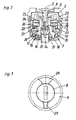
- the present invention relates to an actuating element for adjusting at least one optical property, in particular the position of a target, a target device, in particular a Zielfemrohres, with a rotatable about a rotation axis coupling part on which at least one index element can be pushed.
- the invention also relates to a target device, in particular a telescopic sight, with such an actuating element.
- Generic actuators also referred to as towers, with one or more indexable index elements can be e.g. be used for ballistic correction of a target or a sighting of a target device or a telescopic sight.
- Ballistic correction involves adjusting the target to the ballistic characteristics of the ammunition used or the ballistic characteristics of different types of ammunition depending on the target distance.
- the index elements can then display the respective position of the actuating element and thus of the target mark to be selected for the shot distance and / or the type of ammunition used via corresponding index marks.
- the object of the invention is to improve a generic actuator to the effect that the described unintentional adjustment of the index elements is avoided.
- the actuating element has a guide device for guiding the index element on the coupling part, which allows a sliding of the index element in the direction of the axis of rotation of the coupling part on the coupling part and a rotation of the index element relative to the coupling part in the fully on the coupling part and / or partially pushed state at least in a direction perpendicular to the axis of rotation, preferably in all directions prevented.
- the guide device makes it possible to slide the indexing element (s) onto the coupling part.
- the index elements once they are pushed onto the coupling part, but by means of the guide means rotatably held on this and thus no twisting in a plane perpendicular to the rotation axis is more possible.
- the index elements are thus pushed in the angular position on the coupling part in which they should then remain until they are withdrawn to change the relative position of the index elements again from the coupling part.
- the guide device allows sliding of the index element on the coupling part in several, mutually different, related to the axis of rotation, angular positions. It is advantageous if the plurality of different angular positions, preferably uniformly, are incremented. Under an incrementation is to be understood that the angular positions are not continuous but at discrete intervals from each other, ie a certain division following or stepwise feasible.
- index elements are pushed onto the coupling part, said index elements can be arranged simultaneously on the coupling part.
- the guide device has a toothing with parallel to the axis of rotation of the coupling part and in the pushed onto the coupling part state of the index ring (the index rings) interlocking elevations and depressions.
- the elevations and depressions can be formed in the form of teeth but also otherwise be, as long as they prevent unintentional rotation of the index elements against the coupling part in the pushed state.
- the guide device has a first guide element with at least one elevation or depression and a second guide element with a plurality of elevations or depressions, wherein the at least one elevation or depression of the first guide element in the pushed onto the coupling part state of the index ring (the index rings) with the elevations or depressions of the second guide member is engaged.
- the first guide element on the coupling part preferably arranged on an outer lateral surface of the coupling part, preferably integrally formed
- the second guide element on the index element preferably in a recess of the index element, arranged, preferably integrally formed, or vice versa.
- a particularly preferred embodiment provides that the first guide element and / or the second guide element has a sequence of elevations and depressions extending over an angular range of 360 °, preferably uniformly incremented, elevations and depressions.
- index elements can also be provided on the actuator fixable, preferably screwed onto the actuator cover, which prevents in the fixed state on the actuator peeling or slipping of the index or elements of the coupling part.
- this cover is merely an additional protection. It is not necessary to prevent unwanted twisting of the index elements against the coupling part.
- each of the index elements 4 carries an index mark 13 which makes it possible to quickly find the ballistic correction position necessary for the respective distance and / or type of ammunition.
- the lower ring of the coupling part 3 carries the inscription 27, which show the division or increment of the various angular positions in which the index elements 4 can be pushed onto the coupling part 3.
- Part of the label 27 is the zero point 32, the function of which will be explained below.
- a spindle 14 protrudes, which - as explained in detail below - by turning the coupling part 3 in the locking housing 16 on and is unscrewed.
- the spindle 14 presses - as known per se, but not shown in detail here - on a in the main pipe 1 of the in Fig. 4 Inner tube arranged as an example, which carries the aiming mark or reticle.
- the position of the reticle or the target mark can thus be adjusted in the main tube 1 of the telescopic sight and thus in the direction through the telescopic sight.
- targets all the known in the prior art, for targeting and / or estimating the distance od. Like. Used, markers such as crosshairs come into question.
- the coupling part 3 has in a region which is provided for the attachment of the index elements 4, a substantially cylindrical outer circumferential surface 9.
- substantially cylindrical refers to the basic shape of the outer circumferential surface 9, which from the first Guide element 11 of the guide device is superimposed.
- first guide member 11 As a first guide member 11 a plurality of parallel to the axis of rotation 5 of the coupling part 3 extending elevations and depressions are provided on this outer circumferential surface 9. These are arranged in one piece on the outer circumferential surface 9 in this example. But this does not necessarily have to be the case.
- the index elements 4 are formed substantially annular and each have a substantially circular recess 10, on each of which a second guide member 12 is provided in the form of a toothing of the first guide member 11 complementary toothing. Again, the elevations and depressions of the teeth are integrally formed integrally with the index elements 4. Again, this is not mandatory.
- the toothing of the first and second guide elements 11 and 12 each extend with uniform incrementation or tooth pitch over an angular range of 360 °. This too does not necessarily have to be this way. It would also be sufficient if either the first or the second guide element 11, 12 would have only one elevation or only one depression. This would also ensure a rotationally fixed arrangement of the index elements 4 on the coupling part 3.
- Fig. 4 can be seen by pulling off the coupling part 3 which is otherwise located inside the coupling part arranged adjusting disk 24 and stop plate 22. Also these wear gears, which with a in Fig. 4 invisible internal teeth 26 of the coupling part 3 in the mounted state in engagement.
- a toothing 18 is provided, which in turn has teeth extending parallel to the axis of rotation 5. In this engages a corresponding toothing of the spindle 14, whereby the spindle 14 can be rotated by rotating the coupling part 3.
- the latching housing 16 and thus rotatably connected intermediate housing 19 are rotatably connected in the plugged onto the riflescope state with the main tube 1 of the riflescope.
- the seals 30 guarantee the gas-tight design of the actuating element.
- a latching device 15 is provided, which ensures an incremental, so gradual rotation of the coupling part 3 and the transmission device 7.
- the division or incrementation of the latching device 15 corresponds favorably to the incrementation or division of the toothing of the guide elements 11 and 12 visualized by means of the inscription 27, that is to say the increment provided by the guide device for sliding the index elements 4 onto the coupling part 3.
- stop disc 22 in the plugged state rotatably connected to the coupling part 3 stop disc 22 carries a stop lug 23 which abuts at a corresponding angle of rotation of the fixed to the intermediate housing 19 in its position stop pin 21 and thus limits the maximum possible rotation angle.
- the label 27 is used to adjust the azimuthal positions of the index elements 4 relative to the basic position.
- the label 27 has the zero point 32.
- the number of graduations may be indicated by which the index elements 4 are twisted relative to the zero point 32 to be placed on the coupling part 3, depending on ballistics and target distance. This adjustment thus can be done even with the coupling part removed. After basic adjustment, the coupling part is then placed so that the zero point 32 is above the zero index 20.
- the cover 6 still carries an arrow-like design element 29, which favorably in the in Fig. 1 shown position in which the lowest index mark 13 is located directly above the zero index 20, also in the direction of the zero index 20 points.
- the zero index 20 shows favorably in the direction of in Fig. 4 Not shown eyepieces and thus in the direction of the user. Also in a plan view according Fig. 3 is thus easy to see by the design element 29, whether the actuator is in the default setting or not.
- the cover 6 and the coupling part 3 are first removed from the transmission device 7. As a result, as in Fig. 4 shown, the adjusting disc 24 to light.
- the stop disc 22 is loosely mounted rotatably on the nut 17. After this basic adjustment, the stop disc 22 is rotated until the stop lug 23 touches the stopper pin 21. Thereafter, the coupling part 3 is placed, whereby it comes to a lock between the stop plate 22, adjusting disk 24 and coupling part 3 via the toothing 26. Now, the respective positions of the target can be searched by rotating the spindle 14 in succession for different distances and / or types of ammunition.
- the designated index element 4 is pushed with appropriately aligned index mark 13, whereby the index element 4 is then rotatably mounted on the coupling part 3, so that without a risk of further adjustment of the already deferred index element 4, the position for the next index mark 13 of the next index element 4 can be visited.
- the cover 6 can be screwed by means of the screw 8. The adjustment process is over.
- a guide device does not necessarily have the in Fig. 4 having teeth of the guide elements 11 and 12 shown. It would, for example, alternatively also possible od corresponding teeth. The like. Provide on the outside of the index elements 4, which are then locked by a separate, outside mounted on the coupling part 3 pin in the plugged state against rotation with the coupling part 3.
Landscapes
- Physics & Mathematics (AREA)
- Optics & Photonics (AREA)
- Engineering & Computer Science (AREA)
- General Engineering & Computer Science (AREA)
- Astronomy & Astrophysics (AREA)
- General Physics & Mathematics (AREA)
- Transmission Devices (AREA)
- Aiming, Guidance, Guns With A Light Source, Armor, Camouflage, And Targets (AREA)
- Telescopes (AREA)
- Mechanical Control Devices (AREA)
Applications Claiming Priority (1)
| Application Number | Priority Date | Filing Date | Title |
|---|---|---|---|
| AT0022807A AT504115B1 (de) | 2007-02-14 | 2007-02-14 | Betätigungselement |
Publications (3)
| Publication Number | Publication Date |
|---|---|
| EP1959221A2 true EP1959221A2 (fr) | 2008-08-20 |
| EP1959221A3 EP1959221A3 (fr) | 2010-12-01 |
| EP1959221B1 EP1959221B1 (fr) | 2011-09-21 |
Family
ID=39154301
Family Applications (1)
| Application Number | Title | Priority Date | Filing Date |
|---|---|---|---|
| EP07024030A Active EP1959221B1 (fr) | 2007-02-14 | 2007-12-12 | Elément d'actionnement |
Country Status (3)
| Country | Link |
|---|---|
| US (1) | US8875435B2 (fr) |
| EP (1) | EP1959221B1 (fr) |
| AT (2) | AT504115B1 (fr) |
Cited By (3)
| Publication number | Priority date | Publication date | Assignee | Title |
|---|---|---|---|---|
| AT516059B1 (de) * | 2014-12-15 | 2016-02-15 | Swarovski Optik Kg | Betätigungselement zum Einstellen der Zielmarke eines Zielfernrohrs |
| US10012476B2 (en) | 2014-12-19 | 2018-07-03 | Swarovski-Optik Kg | Actuator element for the target mark of a sighting telescope having a retainer |
| WO2020035110A1 (fr) | 2018-08-15 | 2020-02-20 | Leica Camera Ag | Tourelle de réglage comportant des anneaux indicateurs |
Families Citing this family (18)
| Publication number | Priority date | Publication date | Assignee | Title |
|---|---|---|---|---|
| US7827725B1 (en) * | 2007-04-02 | 2010-11-09 | Lloyd Hagler | Scope assembly |
| US8312667B2 (en) * | 2009-01-14 | 2012-11-20 | Premier Reticles, Ltd | Lockable adjustment mechanism |
| DE202012002286U1 (de) | 2012-03-08 | 2013-06-10 | Carl Zeiss Sports Optics Gmbh | Betätigungselement für die Verstellung oder Einstellung eines Parameters eines optischen Geräts, insbesondere Absehenschnellverstellung für ein Zielfernrohr |
| CZ306573B6 (cs) * | 2012-11-15 | 2017-03-15 | Meopta - Optika, S.R.O. | Přídavné balistické točítko k rektifikátoru pro zaměřovač střelné zbraně |
| US8806798B2 (en) | 2012-11-21 | 2014-08-19 | Leupold & Stevens, Inc. | Riflescope adjustment knob with interchangeable adjustment indicator ring |
| US9885541B2 (en) | 2013-03-15 | 2018-02-06 | Vista Outdoor Operations Llc | Riflescope aiming system |
| US10591253B1 (en) | 2013-03-15 | 2020-03-17 | Tangent Theta Inc. | Finger-adjustable scope adjustment mechanism |
| AT514600B1 (de) * | 2013-09-11 | 2015-02-15 | Swarovski Optik Kg | Verstellturm |
| US9062934B1 (en) * | 2013-12-04 | 2015-06-23 | Trijicon, Inc. | Locking adjuster |
| USD813338S1 (en) | 2015-09-17 | 2018-03-20 | Vista Outdoor Operations Llc | Riflescope turret |
| WO2017197219A2 (fr) | 2016-05-13 | 2017-11-16 | Vista Outdoor Operations Llc | Tourelle à arrêt nul réglable |
| USD829527S1 (en) * | 2016-12-26 | 2018-10-02 | Samsung Electronics Co., Ltd. | Knob for home appliance |
| CN108345345B (zh) * | 2017-01-23 | 2020-02-14 | 信泰光学(深圳)有限公司 | 旋钮调整机构 |
| AT518877B1 (de) * | 2017-02-27 | 2018-02-15 | Swarovski Optik Kg | Verstellelement zur Verstellung einer Visierlinie einer optischen Visiereinrichtung, sowie Zielfernrohr mit dem Verstellelement und Waffe mit dem Zielfernrohr, sowie Verfahren zur Verstellung der Visierlinie |
| SE543936C2 (en) * | 2018-09-12 | 2021-09-28 | Aimpoint Ab | Adjustable reflex sight |
| GB201900665D0 (en) | 2019-01-17 | 2019-03-06 | Deben Group Industries Ltd | 06557607002 |
| USD903466S1 (en) * | 2019-09-10 | 2020-12-01 | DieselPro, LLC | Vehicle accessory knob |
| DE102020101053B4 (de) | 2020-01-17 | 2022-04-21 | Schmidt u. Bender GmbH & Co. KG Optische Geräte | Stellvorrichtung mit verstellbarem Indikatorelement und Zielfernrohr hiermit |
Citations (4)
| Publication number | Priority date | Publication date | Assignee | Title |
|---|---|---|---|---|
| EP0656519A1 (fr) * | 1993-12-02 | 1995-06-07 | Swarovski Optik Kg | Dispositif de réglage de réticule d'une lunette de visée |
| US6691447B1 (en) * | 2002-09-17 | 2004-02-17 | Leupold & Stevens, Inc. | Non-telescoping riflescope adjustment mechanism |
| US20040144013A1 (en) * | 2003-01-25 | 2004-07-29 | Leatherwood James Milner | Rifle scope adjustment invention |
| WO2006017869A1 (fr) * | 2004-08-18 | 2006-02-23 | Kahles Ges. M. B. H. | Element de commande pour une lunette de visee |
Family Cites Families (7)
| Publication number | Priority date | Publication date | Assignee | Title |
|---|---|---|---|---|
| US3280463A (en) * | 1964-05-12 | 1966-10-25 | John T Stadler | Reticle adjusting device for telescopic sights |
| US3990155A (en) * | 1975-12-29 | 1976-11-09 | Bausch & Lomb Incorporated | Riflescope elevation adjustment assembly |
| DE3004635C2 (de) | 1980-02-08 | 1982-01-14 | Walter 7500 Karlsruhe Gehmann | Dioptervisier |
| US6279259B1 (en) * | 1997-10-22 | 2001-08-28 | Leupold & Stevens, Inc. | Rifle scope adjustment mechanism |
| US6643970B2 (en) * | 2002-01-31 | 2003-11-11 | Jeffrey Huber | Zero stop adjustable rifle scope |
| FI116698B (fi) | 2004-07-07 | 2006-01-31 | Sako Oy | Aseen kiikaritähtäin |
| AT414167B (de) | 2004-08-18 | 2006-09-15 | Kahles Ges M B H | Betätigungselement für ein zielfernrohr |
-
2007
- 2007-02-14 AT AT0022807A patent/AT504115B1/de not_active IP Right Cessation
- 2007-12-12 EP EP07024030A patent/EP1959221B1/fr active Active
- 2007-12-12 AT AT07024030T patent/ATE525624T1/de active
-
2008
- 2008-02-01 US US12/068,098 patent/US8875435B2/en active Active
Patent Citations (4)
| Publication number | Priority date | Publication date | Assignee | Title |
|---|---|---|---|---|
| EP0656519A1 (fr) * | 1993-12-02 | 1995-06-07 | Swarovski Optik Kg | Dispositif de réglage de réticule d'une lunette de visée |
| US6691447B1 (en) * | 2002-09-17 | 2004-02-17 | Leupold & Stevens, Inc. | Non-telescoping riflescope adjustment mechanism |
| US20040144013A1 (en) * | 2003-01-25 | 2004-07-29 | Leatherwood James Milner | Rifle scope adjustment invention |
| WO2006017869A1 (fr) * | 2004-08-18 | 2006-02-23 | Kahles Ges. M. B. H. | Element de commande pour une lunette de visee |
Cited By (7)
| Publication number | Priority date | Publication date | Assignee | Title |
|---|---|---|---|---|
| AT516059B1 (de) * | 2014-12-15 | 2016-02-15 | Swarovski Optik Kg | Betätigungselement zum Einstellen der Zielmarke eines Zielfernrohrs |
| AT516059A4 (de) * | 2014-12-15 | 2016-02-15 | Swarovski Optik Kg | Betätigungselement zum Einstellen der Zielmarke eines Zielfernrohrs |
| EP3034981A1 (fr) | 2014-12-15 | 2016-06-22 | Swarovski Optik Kg | Élément d'actionnement destiné à régler le réticule d'une lunette de visée |
| US9989362B2 (en) | 2014-12-15 | 2018-06-05 | Swarovski-Optik Kg. | Actuator element for setting the target mark of a sighting telescope |
| US10365100B2 (en) | 2014-12-15 | 2019-07-30 | Swarovski-Optik Kg. | Actuator element for setting the target mark of a sighting telescope |
| US10012476B2 (en) | 2014-12-19 | 2018-07-03 | Swarovski-Optik Kg | Actuator element for the target mark of a sighting telescope having a retainer |
| WO2020035110A1 (fr) | 2018-08-15 | 2020-02-20 | Leica Camera Ag | Tourelle de réglage comportant des anneaux indicateurs |
Also Published As
| Publication number | Publication date |
|---|---|
| EP1959221B1 (fr) | 2011-09-21 |
| ATE525624T1 (de) | 2011-10-15 |
| AT504115A4 (de) | 2008-03-15 |
| EP1959221A3 (fr) | 2010-12-01 |
| US20080289239A1 (en) | 2008-11-27 |
| US8875435B2 (en) | 2014-11-04 |
| AT504115B1 (de) | 2008-03-15 |
Similar Documents
| Publication | Publication Date | Title |
|---|---|---|
| EP1959221B1 (fr) | Elément d'actionnement | |
| DE102010060343B4 (de) | Selbstarretierende Einstellvorrichtung | |
| EP1843122B1 (fr) | Dispositif de réglage | |
| AT414167B (de) | Betätigungselement für ein zielfernrohr | |
| EP2314978B1 (fr) | Dispositif de réglage arrêtable pour le réglage d'un dispositif de visée | |
| EP2466245B1 (fr) | Dispositif de réglage pour systèmes optiques | |
| AT413884B (de) | Betätigungselement für ein zielfernrohr | |
| EP3190377B1 (fr) | Dispositif de réglage d'une lunette de visée et lunette de visée en étant équipée | |
| AT516034B1 (de) | Betätigungselement für die Zielmarke eines Zielfernrohrs mit einer Arretierung | |
| EP1855075B1 (fr) | Lunette de tir | |
| DE202014000102U1 (de) | Selbstverriegelnder Press-/Dreh-Einstellknopf mit niedrigem Profil | |
| CH649377A5 (de) | Dioptervisier, insbesondere fuer sportgewehre. | |
| WO2019114872A1 (fr) | Tourelle de réglage | |
| EP3586078B1 (fr) | Dispositif de réglage pour un dispositif de visée d'une lunette de visée | |
| EP3171120A1 (fr) | Dispositif de montage de dispositif de visée sur une arme a feu | |
| AT516975B1 (de) | Zielfernrohr mit Verstellvorrichtung | |
| AT518653B1 (de) | Verstellturm für eine fernoptische Einrichtung | |
| AT521030B1 (de) | Stellturm zur Seitenverstellung einer Zielmarke eines Zielfernrohrs | |
| EP3851785B1 (fr) | Dispositif de réglage pourvu d'élément indicateur réglable et lunette associée | |
| DE2638506A1 (de) | Mechanismus fuer spielraum- oder hoeheneinstellungen der visierlinie eines gewehrzielfernrohres | |
| DE202018100925U1 (de) | Visiereinrichtung für Schusswaffen, insbesondere für Kurzwaffen | |
| DE102015120119A1 (de) | Montagevorrichtung für eine Zieleinrichtung an einer Handfeuerwaffe | |
| CH520385A (de) | Vorrichtung mit zwei Verstellmitteln | |
| DE7927872U1 (de) | Adapterring |
Legal Events
| Date | Code | Title | Description |
|---|---|---|---|
| PUAI | Public reference made under article 153(3) epc to a published international application that has entered the european phase |
Free format text: ORIGINAL CODE: 0009012 |
|
| AK | Designated contracting states |
Kind code of ref document: A2 Designated state(s): AT BE BG CH CY CZ DE DK EE ES FI FR GB GR HU IE IS IT LI LT LU LV MC MT NL PL PT RO SE SI SK TR |
|
| AX | Request for extension of the european patent |
Extension state: AL BA HR MK RS |
|
| PUAL | Search report despatched |
Free format text: ORIGINAL CODE: 0009013 |
|
| AK | Designated contracting states |
Kind code of ref document: A3 Designated state(s): AT BE BG CH CY CZ DE DK EE ES FI FR GB GR HU IE IS IT LI LT LU LV MC MT NL PL PT RO SE SI SK TR |
|
| AX | Request for extension of the european patent |
Extension state: AL BA HR MK RS |
|
| GRAP | Despatch of communication of intention to grant a patent |
Free format text: ORIGINAL CODE: EPIDOSNIGR1 |
|
| 17P | Request for examination filed |
Effective date: 20110311 |
|
| RIC1 | Information provided on ipc code assigned before grant |
Ipc: F41G 11/00 20060101ALI20110331BHEP Ipc: F41G 1/00 20060101AFI20110331BHEP |
|
| GRAS | Grant fee paid |
Free format text: ORIGINAL CODE: EPIDOSNIGR3 |
|
| AKX | Designation fees paid |
Designated state(s): AT BE BG CH CY CZ DE DK EE ES FI FR GB GR HU IE IS IT LI LT LU LV MC MT NL PL PT RO SE SI SK TR |
|
| GRAA | (expected) grant |
Free format text: ORIGINAL CODE: 0009210 |
|
| RAP1 | Party data changed (applicant data changed or rights of an application transferred) |
Owner name: SWAROVSKI-OPTIK KG |
|
| AK | Designated contracting states |
Kind code of ref document: B1 Designated state(s): AT BE BG CH CY CZ DE DK EE ES FI FR GB GR HU IE IS IT LI LT LU LV MC MT NL PL PT RO SE SI SK TR |
|
| REG | Reference to a national code |
Ref country code: GB Ref legal event code: FG4D Free format text: NOT ENGLISH |
|
| REG | Reference to a national code |
Ref country code: CH Ref legal event code: EP |
|
| REG | Reference to a national code |
Ref country code: IE Ref legal event code: FG4D Free format text: LANGUAGE OF EP DOCUMENT: GERMAN |
|
| REG | Reference to a national code |
Ref country code: DE Ref legal event code: R096 Ref document number: 502007008196 Country of ref document: DE Effective date: 20111117 |
|
| REG | Reference to a national code |
Ref country code: SE Ref legal event code: TRGR |
|
| REG | Reference to a national code |
Ref country code: NL Ref legal event code: VDEP Effective date: 20110921 |
|
| PG25 | Lapsed in a contracting state [announced via postgrant information from national office to epo] |
Ref country code: FI Free format text: LAPSE BECAUSE OF FAILURE TO SUBMIT A TRANSLATION OF THE DESCRIPTION OR TO PAY THE FEE WITHIN THE PRESCRIBED TIME-LIMIT Effective date: 20110921 Ref country code: LT Free format text: LAPSE BECAUSE OF FAILURE TO SUBMIT A TRANSLATION OF THE DESCRIPTION OR TO PAY THE FEE WITHIN THE PRESCRIBED TIME-LIMIT Effective date: 20110921 |
|
| LTIE | Lt: invalidation of european patent or patent extension |
Effective date: 20110921 |
|
| PG25 | Lapsed in a contracting state [announced via postgrant information from national office to epo] |
Ref country code: LV Free format text: LAPSE BECAUSE OF FAILURE TO SUBMIT A TRANSLATION OF THE DESCRIPTION OR TO PAY THE FEE WITHIN THE PRESCRIBED TIME-LIMIT Effective date: 20110921 Ref country code: CY Free format text: LAPSE BECAUSE OF FAILURE TO SUBMIT A TRANSLATION OF THE DESCRIPTION OR TO PAY THE FEE WITHIN THE PRESCRIBED TIME-LIMIT Effective date: 20110921 Ref country code: GR Free format text: LAPSE BECAUSE OF FAILURE TO SUBMIT A TRANSLATION OF THE DESCRIPTION OR TO PAY THE FEE WITHIN THE PRESCRIBED TIME-LIMIT Effective date: 20111222 Ref country code: SI Free format text: LAPSE BECAUSE OF FAILURE TO SUBMIT A TRANSLATION OF THE DESCRIPTION OR TO PAY THE FEE WITHIN THE PRESCRIBED TIME-LIMIT Effective date: 20110921 |
|
| REG | Reference to a national code |
Ref country code: IE Ref legal event code: FD4D |
|
| PG25 | Lapsed in a contracting state [announced via postgrant information from national office to epo] |
Ref country code: IE Free format text: LAPSE BECAUSE OF FAILURE TO SUBMIT A TRANSLATION OF THE DESCRIPTION OR TO PAY THE FEE WITHIN THE PRESCRIBED TIME-LIMIT Effective date: 20110921 Ref country code: SK Free format text: LAPSE BECAUSE OF FAILURE TO SUBMIT A TRANSLATION OF THE DESCRIPTION OR TO PAY THE FEE WITHIN THE PRESCRIBED TIME-LIMIT Effective date: 20110921 Ref country code: IS Free format text: LAPSE BECAUSE OF FAILURE TO SUBMIT A TRANSLATION OF THE DESCRIPTION OR TO PAY THE FEE WITHIN THE PRESCRIBED TIME-LIMIT Effective date: 20120121 |
|
| PG25 | Lapsed in a contracting state [announced via postgrant information from national office to epo] |
Ref country code: PT Free format text: LAPSE BECAUSE OF FAILURE TO SUBMIT A TRANSLATION OF THE DESCRIPTION OR TO PAY THE FEE WITHIN THE PRESCRIBED TIME-LIMIT Effective date: 20120123 Ref country code: NL Free format text: LAPSE BECAUSE OF FAILURE TO SUBMIT A TRANSLATION OF THE DESCRIPTION OR TO PAY THE FEE WITHIN THE PRESCRIBED TIME-LIMIT Effective date: 20110921 Ref country code: RO Free format text: LAPSE BECAUSE OF FAILURE TO SUBMIT A TRANSLATION OF THE DESCRIPTION OR TO PAY THE FEE WITHIN THE PRESCRIBED TIME-LIMIT Effective date: 20110921 Ref country code: EE Free format text: LAPSE BECAUSE OF FAILURE TO SUBMIT A TRANSLATION OF THE DESCRIPTION OR TO PAY THE FEE WITHIN THE PRESCRIBED TIME-LIMIT Effective date: 20110921 Ref country code: PL Free format text: LAPSE BECAUSE OF FAILURE TO SUBMIT A TRANSLATION OF THE DESCRIPTION OR TO PAY THE FEE WITHIN THE PRESCRIBED TIME-LIMIT Effective date: 20110921 |
|
| BERE | Be: lapsed |
Owner name: SWAROVSKI-OPTIK KG. Effective date: 20111231 |
|
| PLBE | No opposition filed within time limit |
Free format text: ORIGINAL CODE: 0009261 |
|
| STAA | Information on the status of an ep patent application or granted ep patent |
Free format text: STATUS: NO OPPOSITION FILED WITHIN TIME LIMIT |
|
| PG25 | Lapsed in a contracting state [announced via postgrant information from national office to epo] |
Ref country code: DK Free format text: LAPSE BECAUSE OF FAILURE TO SUBMIT A TRANSLATION OF THE DESCRIPTION OR TO PAY THE FEE WITHIN THE PRESCRIBED TIME-LIMIT Effective date: 20110921 Ref country code: MC Free format text: LAPSE BECAUSE OF NON-PAYMENT OF DUE FEES Effective date: 20111231 |
|
| REG | Reference to a national code |
Ref country code: CH Ref legal event code: PL |
|
| 26N | No opposition filed |
Effective date: 20120622 |
|
| REG | Reference to a national code |
Ref country code: DE Ref legal event code: R097 Ref document number: 502007008196 Country of ref document: DE Effective date: 20120622 |
|
| PG25 | Lapsed in a contracting state [announced via postgrant information from national office to epo] |
Ref country code: LI Free format text: LAPSE BECAUSE OF NON-PAYMENT OF DUE FEES Effective date: 20111231 Ref country code: CH Free format text: LAPSE BECAUSE OF NON-PAYMENT OF DUE FEES Effective date: 20111231 Ref country code: BE Free format text: LAPSE BECAUSE OF NON-PAYMENT OF DUE FEES Effective date: 20111231 |
|
| PG25 | Lapsed in a contracting state [announced via postgrant information from national office to epo] |
Ref country code: MT Free format text: LAPSE BECAUSE OF FAILURE TO SUBMIT A TRANSLATION OF THE DESCRIPTION OR TO PAY THE FEE WITHIN THE PRESCRIBED TIME-LIMIT Effective date: 20110921 |
|
| PG25 | Lapsed in a contracting state [announced via postgrant information from national office to epo] |
Ref country code: ES Free format text: LAPSE BECAUSE OF FAILURE TO SUBMIT A TRANSLATION OF THE DESCRIPTION OR TO PAY THE FEE WITHIN THE PRESCRIBED TIME-LIMIT Effective date: 20120101 |
|
| PG25 | Lapsed in a contracting state [announced via postgrant information from national office to epo] |
Ref country code: LU Free format text: LAPSE BECAUSE OF NON-PAYMENT OF DUE FEES Effective date: 20111212 |
|
| PG25 | Lapsed in a contracting state [announced via postgrant information from national office to epo] |
Ref country code: BG Free format text: LAPSE BECAUSE OF FAILURE TO SUBMIT A TRANSLATION OF THE DESCRIPTION OR TO PAY THE FEE WITHIN THE PRESCRIBED TIME-LIMIT Effective date: 20111221 |
|
| PG25 | Lapsed in a contracting state [announced via postgrant information from national office to epo] |
Ref country code: TR Free format text: LAPSE BECAUSE OF FAILURE TO SUBMIT A TRANSLATION OF THE DESCRIPTION OR TO PAY THE FEE WITHIN THE PRESCRIBED TIME-LIMIT Effective date: 20110921 |
|
| PG25 | Lapsed in a contracting state [announced via postgrant information from national office to epo] |
Ref country code: HU Free format text: LAPSE BECAUSE OF FAILURE TO SUBMIT A TRANSLATION OF THE DESCRIPTION OR TO PAY THE FEE WITHIN THE PRESCRIBED TIME-LIMIT Effective date: 20110921 |
|
| REG | Reference to a national code |
Ref country code: FR Ref legal event code: PLFP Year of fee payment: 9 |
|
| PGFP | Annual fee paid to national office [announced via postgrant information from national office to epo] |
Ref country code: IT Payment date: 20151126 Year of fee payment: 9 |
|
| PGFP | Annual fee paid to national office [announced via postgrant information from national office to epo] |
Ref country code: SE Payment date: 20151217 Year of fee payment: 9 Ref country code: FR Payment date: 20151124 Year of fee payment: 9 |
|
| PGFP | Annual fee paid to national office [announced via postgrant information from national office to epo] |
Ref country code: GB Payment date: 20161212 Year of fee payment: 10 |
|
| REG | Reference to a national code |
Ref country code: SE Ref legal event code: EUG |
|
| PG25 | Lapsed in a contracting state [announced via postgrant information from national office to epo] |
Ref country code: SE Free format text: LAPSE BECAUSE OF NON-PAYMENT OF DUE FEES Effective date: 20161213 |
|
| REG | Reference to a national code |
Ref country code: FR Ref legal event code: ST Effective date: 20170831 |
|
| PG25 | Lapsed in a contracting state [announced via postgrant information from national office to epo] |
Ref country code: FR Free format text: LAPSE BECAUSE OF NON-PAYMENT OF DUE FEES Effective date: 20170102 Ref country code: IT Free format text: LAPSE BECAUSE OF NON-PAYMENT OF DUE FEES Effective date: 20161212 |
|
| GBPC | Gb: european patent ceased through non-payment of renewal fee |
Effective date: 20171212 |
|
| PG25 | Lapsed in a contracting state [announced via postgrant information from national office to epo] |
Ref country code: GB Free format text: LAPSE BECAUSE OF NON-PAYMENT OF DUE FEES Effective date: 20171212 |
|
| REG | Reference to a national code |
Ref country code: DE Ref legal event code: R081 Ref document number: 502007008196 Country of ref document: DE Owner name: SWAROVSKI-OPTIK AG & CO KG., AT Free format text: FORMER OWNER: SWAROVSKI-OPTIK KG., ABSAM/HALL, TIROL, AT Ref country code: DE Ref legal event code: R081 Ref document number: 502007008196 Country of ref document: DE Owner name: SWAROVSKI-OPTIK AG & CO. KG, AT Free format text: FORMER OWNER: SWAROVSKI-OPTIK KG., ABSAM/HALL, TIROL, AT |
|
| REG | Reference to a national code |
Ref country code: DE Ref legal event code: R081 Ref document number: 502007008196 Country of ref document: DE Owner name: SWAROVSKI-OPTIK AG & CO KG., AT Free format text: FORMER OWNER: SWAROVSKI-OPTIK AG & CO. KG, ABSAM, AT |
|
| PGFP | Annual fee paid to national office [announced via postgrant information from national office to epo] |
Ref country code: CZ Payment date: 20231124 Year of fee payment: 17 Ref country code: AT Payment date: 20231228 Year of fee payment: 17 |
|
| PGFP | Annual fee paid to national office [announced via postgrant information from national office to epo] |
Ref country code: DE Payment date: 20240102 Year of fee payment: 17 |