EP1959143B1 - Dispositif de contrôle de la pression dans une pompe à huile - Google Patents
Dispositif de contrôle de la pression dans une pompe à huile Download PDFInfo
- Publication number
- EP1959143B1 EP1959143B1 EP20070122704 EP07122704A EP1959143B1 EP 1959143 B1 EP1959143 B1 EP 1959143B1 EP 20070122704 EP20070122704 EP 20070122704 EP 07122704 A EP07122704 A EP 07122704A EP 1959143 B1 EP1959143 B1 EP 1959143B1
- Authority
- EP
- European Patent Office
- Prior art keywords
- rotor assembly
- discharge
- pressure
- passage
- discharge passage
- Prior art date
- Legal status (The legal status is an assumption and is not a legal conclusion. Google has not performed a legal analysis and makes no representation as to the accuracy of the status listed.)
- Expired - Fee Related
Links
Images


Classifications
-
- F—MECHANICAL ENGINEERING; LIGHTING; HEATING; WEAPONS; BLASTING
- F04—POSITIVE - DISPLACEMENT MACHINES FOR LIQUIDS; PUMPS FOR LIQUIDS OR ELASTIC FLUIDS
- F04C—ROTARY-PISTON, OR OSCILLATING-PISTON, POSITIVE-DISPLACEMENT MACHINES FOR LIQUIDS; ROTARY-PISTON, OR OSCILLATING-PISTON, POSITIVE-DISPLACEMENT PUMPS
- F04C14/00—Control of, monitoring of, or safety arrangements for, machines, pumps or pumping installations
- F04C14/24—Control of, monitoring of, or safety arrangements for, machines, pumps or pumping installations characterised by using valves controlling pressure or flow rate, e.g. discharge valves or unloading valves
- F04C14/26—Control of, monitoring of, or safety arrangements for, machines, pumps or pumping installations characterised by using valves controlling pressure or flow rate, e.g. discharge valves or unloading valves using bypass channels
-
- F—MECHANICAL ENGINEERING; LIGHTING; HEATING; WEAPONS; BLASTING
- F04—POSITIVE - DISPLACEMENT MACHINES FOR LIQUIDS; PUMPS FOR LIQUIDS OR ELASTIC FLUIDS
- F04C—ROTARY-PISTON, OR OSCILLATING-PISTON, POSITIVE-DISPLACEMENT MACHINES FOR LIQUIDS; ROTARY-PISTON, OR OSCILLATING-PISTON, POSITIVE-DISPLACEMENT PUMPS
- F04C14/00—Control of, monitoring of, or safety arrangements for, machines, pumps or pumping installations
- F04C14/06—Control of, monitoring of, or safety arrangements for, machines, pumps or pumping installations specially adapted for stopping, starting, idling or no-load operation
- F04C14/065—Capacity control using a multiplicity of units or pumping capacities, e.g. multiple chambers, individually switchable or controllable
-
- F—MECHANICAL ENGINEERING; LIGHTING; HEATING; WEAPONS; BLASTING
- F04—POSITIVE - DISPLACEMENT MACHINES FOR LIQUIDS; PUMPS FOR LIQUIDS OR ELASTIC FLUIDS
- F04C—ROTARY-PISTON, OR OSCILLATING-PISTON, POSITIVE-DISPLACEMENT MACHINES FOR LIQUIDS; ROTARY-PISTON, OR OSCILLATING-PISTON, POSITIVE-DISPLACEMENT PUMPS
- F04C2/00—Rotary-piston machines or pumps
- F04C2/08—Rotary-piston machines or pumps of intermeshing-engagement type, i.e. with engagement of co-operating members similar to that of toothed gearing
- F04C2/10—Rotary-piston machines or pumps of intermeshing-engagement type, i.e. with engagement of co-operating members similar to that of toothed gearing of internal-axis type with the outer member having more teeth or tooth-equivalents, e.g. rollers, than the inner member
-
- F—MECHANICAL ENGINEERING; LIGHTING; HEATING; WEAPONS; BLASTING
- F04—POSITIVE - DISPLACEMENT MACHINES FOR LIQUIDS; PUMPS FOR LIQUIDS OR ELASTIC FLUIDS
- F04C—ROTARY-PISTON, OR OSCILLATING-PISTON, POSITIVE-DISPLACEMENT MACHINES FOR LIQUIDS; ROTARY-PISTON, OR OSCILLATING-PISTON, POSITIVE-DISPLACEMENT PUMPS
- F04C2/00—Rotary-piston machines or pumps
- F04C2/08—Rotary-piston machines or pumps of intermeshing-engagement type, i.e. with engagement of co-operating members similar to that of toothed gearing
- F04C2/12—Rotary-piston machines or pumps of intermeshing-engagement type, i.e. with engagement of co-operating members similar to that of toothed gearing of other than internal-axis type
- F04C2/14—Rotary-piston machines or pumps of intermeshing-engagement type, i.e. with engagement of co-operating members similar to that of toothed gearing of other than internal-axis type with toothed rotary pistons
- F04C2/18—Rotary-piston machines or pumps of intermeshing-engagement type, i.e. with engagement of co-operating members similar to that of toothed gearing of other than internal-axis type with toothed rotary pistons with similar tooth forms
-
- Y—GENERAL TAGGING OF NEW TECHNOLOGICAL DEVELOPMENTS; GENERAL TAGGING OF CROSS-SECTIONAL TECHNOLOGIES SPANNING OVER SEVERAL SECTIONS OF THE IPC; TECHNICAL SUBJECTS COVERED BY FORMER USPC CROSS-REFERENCE ART COLLECTIONS [XRACs] AND DIGESTS
- Y10—TECHNICAL SUBJECTS COVERED BY FORMER USPC
- Y10T—TECHNICAL SUBJECTS COVERED BY FORMER US CLASSIFICATION
- Y10T137/00—Fluid handling
- Y10T137/8593—Systems
- Y10T137/85978—With pump
- Y10T137/85986—Pumped fluid control
- Y10T137/86002—Fluid pressure responsive
- Y10T137/86019—Direct response valve
Definitions
- the aforementioned problems were able to be solved by the additional features of claim 2 according to the configuration described above by the first rotor assembly and the second rotor assembly each being configured to serve as respectively separate oil pumps.
- the aforementioned problems were found to be solved by the additional features of claim 3 according to the configuration described above by the first rotor assembly and the second rotor assembly being configured as a single oil pump with at least three rotors.
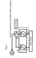
- the device is configured from a first discharge passage 1 for feeding oil to an engine E, a first return passage 2 that returns to an intake passage 8 of the aforementioned first rotor assembly A, a second discharge passage 3 for feeding oil to the engine E, and a second return passage 4 that returns to an intake passage 9 of the aforementioned second rotor assembly B, an end portion side of the aforementioned second discharge passage 3 being coupled with the aforementioned first discharge passage 1 at a suitable position therealong.
- the first rotor assembly A and second rotor assembly B of this first embodiment constitute respectively separate pumps and, as shown in FIG. 1 , the first rotor assembly A serving as an oil pump is configured from an outer rotor 111, an inner rotor 112, a discharge port 113 and an intake port 114.
- the second rotor assembly B serving as an oil pump is configured from an outer rotor 122, an inner rotor 121, a discharge port 123 and an intake port 124.
- the symbols 115 and 125 each denote drive shaft
- a state in which the engine revolution number has risen further is taken as the intermediate revolution range.
- this state which constitutes the state of FIG. 2
- an opening portion 41 of the second return passage 4 has started to open, and an opening portion 31 of the second discharge passage 3 has started to close.
- the first discharge passage 1 of the first rotor assembly A and the second discharge passage 3 of the second rotor assembly B remains in communication.
- the opening portion 41 of the second return passage 4 of the second rotor assembly B starting to open, first, the rise in pressure in the second rotor assembly B stops.
- the operation of the pressure control valve C of the first rotor assembly A and second rotor assembly B of the third embodiment will be hereinafter described.
- the operation of the first valve portion 51 and second valve portion 52 of the pressure control valve C is the same as that of FIG. 1 and, accordingly, a description thereof has been omitted.
- the characteristics in the low revolution range under these conditions are shown in the characteristics graph of the revolution number and discharge pressure [see FIG. 5A ] or characteristics graph of revolution number and discharge flow rate [see FIG. 5B ].
Claims (3)
- Un dispositif de régulation de pression dans une pompe à huile comprenant : un premier passage de décharge (1) pour alimenter l'huile venant d'un premier ensemble rotor (A) à un moteur ; un premier passage de retour (2) qui retourne à un côté admission (8) du premier ensemble rotor (A) ; un deuxième passage de décharge (3) pour alimenter l'huile venant d'un deuxième ensemble rotor (B) au moteur ; un deuxième passage de retour (4) qui retourne à un côté admission (9) du deuxième ensemble rotor (B) ; et un clapet de régulation de pression (C) dont le corps du clapet principal (5) configuré dans une première partie du clapet (51), une partie accouplement à diamètre étroit (53) et une deuxième partie du clapet (52) est fournie entre l'orifice de retour (123) venant du deuxième ensemble rotor (B) et le premier passage de décharge (1), caractérisé en ce que
le premier passage de décharge (1) et le deuxième passage de décharge (3) sont accouplés, et une régulation du passage de l'écoulement est exécutée dans chacune de : une basse gamme de révolutions dans un état dans lequel seulement le premier passage de décharge (1) et le deuxième passage de décharge (3) sont ouverts ; une gamme de révolutions intermédiaire dans un état dans lequel le premier passage de décharge (1) et le deuxième passage de décharge (3) sont ouverts et le premier passage de retour (2) est fermé pendant que le deuxième passage de retour (4) est ouvert ; et une gamme de révolutions élevée dans un état dans lequel le deuxième passage de décharge (3) est fermé pendant que le premier passage de décharge (1) est ouvert et que le premier passage de retour (2) et le deuxième passage de retour (4) sont ouverts. - Le dispositif de régulation de pression dans une pompe à huile selon la revendication 1, où le premier ensemble rotor et le deuxième ensemble rotor sont chacun configurés pour servir de pompes distinctes.
- Le dispositif de régulation de pression dans une pompe à huile selon la revendication 1, où le premier ensemble rotor et le deuxième ensemble rotor sont configurés dans une seule pompe à huile comprenant au moins trois rotors.
Applications Claiming Priority (2)
| Application Number | Priority Date | Filing Date | Title |
|---|---|---|---|
| JP2007032715 | 2007-02-13 | ||
| JP2007237536A JP4796026B2 (ja) | 2007-02-13 | 2007-09-13 | オイルポンプにおける圧力制御装置 |
Publications (3)
| Publication Number | Publication Date |
|---|---|
| EP1959143A2 EP1959143A2 (fr) | 2008-08-20 |
| EP1959143A3 EP1959143A3 (fr) | 2009-09-16 |
| EP1959143B1 true EP1959143B1 (fr) | 2010-10-20 |
Family
ID=39446106
Family Applications (1)
| Application Number | Title | Priority Date | Filing Date |
|---|---|---|---|
| EP20070122704 Expired - Fee Related EP1959143B1 (fr) | 2007-02-13 | 2007-12-10 | Dispositif de contrôle de la pression dans une pompe à huile |
Country Status (2)
| Country | Link |
|---|---|
| US (1) | US8038416B2 (fr) |
| EP (1) | EP1959143B1 (fr) |
Families Citing this family (76)
| Publication number | Priority date | Publication date | Assignee | Title |
|---|---|---|---|---|
| CN101981272B (zh) | 2008-03-28 | 2014-06-11 | 埃克森美孚上游研究公司 | 低排放发电和烃采收系统及方法 |
| CN101981162B (zh) | 2008-03-28 | 2014-07-02 | 埃克森美孚上游研究公司 | 低排放发电和烃采收系统及方法 |
| AU2009303735B2 (en) | 2008-10-14 | 2014-06-26 | Exxonmobil Upstream Research Company | Methods and systems for controlling the products of combustion |
| US11493037B1 (en) | 2014-05-21 | 2022-11-08 | Laverne Schumann | Pump system |
| FR2950863B1 (fr) * | 2009-10-06 | 2012-03-02 | Snecma | Circuit d'alimentation en carburant d'un moteur d'aeronef |
| BR112012010294A2 (pt) | 2009-11-12 | 2017-11-07 | Exxonmobil Upstream Res Co | sistema integrado, e, método para a recuperação de hidrocarboneto de baixa emissão com produção de energia |
| AU2011271634B2 (en) | 2010-07-02 | 2016-01-28 | Exxonmobil Upstream Research Company | Stoichiometric combustion with exhaust gas recirculation and direct contact cooler |
| BR112012031505A2 (pt) | 2010-07-02 | 2016-11-01 | Exxonmobil Upstream Res Co | combustão estequiométrica de ar enriquecido com recirculação de gás de exaustão |
| US9903271B2 (en) | 2010-07-02 | 2018-02-27 | Exxonmobil Upstream Research Company | Low emission triple-cycle power generation and CO2 separation systems and methods |
| TWI554325B (zh) | 2010-07-02 | 2016-10-21 | 艾克頌美孚上游研究公司 | 低排放發電系統和方法 |
| JP5232843B2 (ja) * | 2010-09-16 | 2013-07-10 | 株式会社山田製作所 | 可変流量オイルポンプ |
| JP5278775B2 (ja) | 2010-12-06 | 2013-09-04 | アイシン精機株式会社 | 油供給装置 |
| TWI593872B (zh) | 2011-03-22 | 2017-08-01 | 艾克頌美孚上游研究公司 | 整合系統及產生動力之方法 |
| TWI563166B (en) | 2011-03-22 | 2016-12-21 | Exxonmobil Upstream Res Co | Integrated generation systems and methods for generating power |
| TWI564474B (zh) | 2011-03-22 | 2017-01-01 | 艾克頌美孚上游研究公司 | 於渦輪系統中控制化學計量燃燒的整合系統和使用彼之產生動力的方法 |
| TWI563165B (en) | 2011-03-22 | 2016-12-21 | Exxonmobil Upstream Res Co | Power generation system and method for generating power |
| CN104136716B (zh) * | 2011-11-23 | 2016-11-16 | 安东尼奥·多米特 | 具有旋转活塞和气缸的旋转发动机及操作方法 |
| US9810050B2 (en) | 2011-12-20 | 2017-11-07 | Exxonmobil Upstream Research Company | Enhanced coal-bed methane production |
| JP5923361B2 (ja) | 2012-03-28 | 2016-05-24 | 株式会社山田製作所 | 可変流量オイルポンプを備えたエンジン |
| US9353682B2 (en) | 2012-04-12 | 2016-05-31 | General Electric Company | Methods, systems and apparatus relating to combustion turbine power plants with exhaust gas recirculation |
| US10273880B2 (en) | 2012-04-26 | 2019-04-30 | General Electric Company | System and method of recirculating exhaust gas for use in a plurality of flow paths in a gas turbine engine |
| US9784185B2 (en) | 2012-04-26 | 2017-10-10 | General Electric Company | System and method for cooling a gas turbine with an exhaust gas provided by the gas turbine |
| US10215412B2 (en) | 2012-11-02 | 2019-02-26 | General Electric Company | System and method for load control with diffusion combustion in a stoichiometric exhaust gas recirculation gas turbine system |
| US10100741B2 (en) | 2012-11-02 | 2018-10-16 | General Electric Company | System and method for diffusion combustion with oxidant-diluent mixing in a stoichiometric exhaust gas recirculation gas turbine system |
| US9599070B2 (en) | 2012-11-02 | 2017-03-21 | General Electric Company | System and method for oxidant compression in a stoichiometric exhaust gas recirculation gas turbine system |
| US9611756B2 (en) | 2012-11-02 | 2017-04-04 | General Electric Company | System and method for protecting components in a gas turbine engine with exhaust gas recirculation |
| US9869279B2 (en) | 2012-11-02 | 2018-01-16 | General Electric Company | System and method for a multi-wall turbine combustor |
| US9574496B2 (en) | 2012-12-28 | 2017-02-21 | General Electric Company | System and method for a turbine combustor |
| US9803865B2 (en) | 2012-12-28 | 2017-10-31 | General Electric Company | System and method for a turbine combustor |
| US10107495B2 (en) | 2012-11-02 | 2018-10-23 | General Electric Company | Gas turbine combustor control system for stoichiometric combustion in the presence of a diluent |
| US9708977B2 (en) | 2012-12-28 | 2017-07-18 | General Electric Company | System and method for reheat in gas turbine with exhaust gas recirculation |
| US9631815B2 (en) | 2012-12-28 | 2017-04-25 | General Electric Company | System and method for a turbine combustor |
| US9194295B2 (en) * | 2012-11-26 | 2015-11-24 | Hamilton Sundstrand Corporation | Lubrication cut-off at high speed |
| US10208677B2 (en) | 2012-12-31 | 2019-02-19 | General Electric Company | Gas turbine load control system |
| US9581081B2 (en) | 2013-01-13 | 2017-02-28 | General Electric Company | System and method for protecting components in a gas turbine engine with exhaust gas recirculation |
| US9512759B2 (en) | 2013-02-06 | 2016-12-06 | General Electric Company | System and method for catalyst heat utilization for gas turbine with exhaust gas recirculation |
| TW201502356A (zh) | 2013-02-21 | 2015-01-16 | Exxonmobil Upstream Res Co | 氣渦輪機排氣中氧之減少 |
| US9938861B2 (en) | 2013-02-21 | 2018-04-10 | Exxonmobil Upstream Research Company | Fuel combusting method |
| DK177834B1 (en) * | 2013-02-27 | 2014-09-08 | C C Jensen As | Device for processing a liquid under vacuum pressure |
| RU2637609C2 (ru) | 2013-02-28 | 2017-12-05 | Эксонмобил Апстрим Рисерч Компани | Система и способ для камеры сгорания турбины |
| US20140250945A1 (en) | 2013-03-08 | 2014-09-11 | Richard A. Huntington | Carbon Dioxide Recovery |
| US9618261B2 (en) | 2013-03-08 | 2017-04-11 | Exxonmobil Upstream Research Company | Power generation and LNG production |
| WO2014137648A1 (fr) | 2013-03-08 | 2014-09-12 | Exxonmobil Upstream Research Company | Production d'énergie et récupération de méthane à partir d'hydrates de méthane |
| TW201500635A (zh) | 2013-03-08 | 2015-01-01 | Exxonmobil Upstream Res Co | 處理廢氣以供用於提高油回收 |
| KR101534697B1 (ko) * | 2013-05-09 | 2015-07-07 | 현대자동차 주식회사 | 오일 공급 시스템 |
| US9631542B2 (en) | 2013-06-28 | 2017-04-25 | General Electric Company | System and method for exhausting combustion gases from gas turbine engines |
| US9617914B2 (en) | 2013-06-28 | 2017-04-11 | General Electric Company | Systems and methods for monitoring gas turbine systems having exhaust gas recirculation |
| TWI654368B (zh) | 2013-06-28 | 2019-03-21 | 美商艾克頌美孚上游研究公司 | 用於控制在廢氣再循環氣渦輪機系統中的廢氣流之系統、方法與媒體 |
| US9835089B2 (en) | 2013-06-28 | 2017-12-05 | General Electric Company | System and method for a fuel nozzle |
| US9587510B2 (en) | 2013-07-30 | 2017-03-07 | General Electric Company | System and method for a gas turbine engine sensor |
| US9903588B2 (en) | 2013-07-30 | 2018-02-27 | General Electric Company | System and method for barrier in passage of combustor of gas turbine engine with exhaust gas recirculation |
| US9951658B2 (en) | 2013-07-31 | 2018-04-24 | General Electric Company | System and method for an oxidant heating system |
| KR101518895B1 (ko) * | 2013-09-11 | 2015-05-11 | 현대자동차 주식회사 | 차량용 자동변속기의 유압공급시스템 |
| US9752458B2 (en) | 2013-12-04 | 2017-09-05 | General Electric Company | System and method for a gas turbine engine |
| US10030588B2 (en) | 2013-12-04 | 2018-07-24 | General Electric Company | Gas turbine combustor diagnostic system and method |
| US10227920B2 (en) | 2014-01-15 | 2019-03-12 | General Electric Company | Gas turbine oxidant separation system |
| US9863267B2 (en) | 2014-01-21 | 2018-01-09 | General Electric Company | System and method of control for a gas turbine engine |
| US9915200B2 (en) | 2014-01-21 | 2018-03-13 | General Electric Company | System and method for controlling the combustion process in a gas turbine operating with exhaust gas recirculation |
| US10079564B2 (en) | 2014-01-27 | 2018-09-18 | General Electric Company | System and method for a stoichiometric exhaust gas recirculation gas turbine system |
| US10047633B2 (en) | 2014-05-16 | 2018-08-14 | General Electric Company | Bearing housing |
| US11365732B1 (en) | 2014-05-21 | 2022-06-21 | Laverne Schumann | High volume pump system |
| US10060359B2 (en) | 2014-06-30 | 2018-08-28 | General Electric Company | Method and system for combustion control for gas turbine system with exhaust gas recirculation |
| US9885290B2 (en) | 2014-06-30 | 2018-02-06 | General Electric Company | Erosion suppression system and method in an exhaust gas recirculation gas turbine system |
| US10655542B2 (en) | 2014-06-30 | 2020-05-19 | General Electric Company | Method and system for startup of gas turbine system drive trains with exhaust gas recirculation |
| WO2016014978A1 (fr) * | 2014-07-24 | 2016-01-28 | Schumann Laverne | Système de pompe |
| US9869247B2 (en) | 2014-12-31 | 2018-01-16 | General Electric Company | Systems and methods of estimating a combustion equivalence ratio in a gas turbine with exhaust gas recirculation |
| US9819292B2 (en) | 2014-12-31 | 2017-11-14 | General Electric Company | Systems and methods to respond to grid overfrequency events for a stoichiometric exhaust recirculation gas turbine |
| US10788212B2 (en) | 2015-01-12 | 2020-09-29 | General Electric Company | System and method for an oxidant passageway in a gas turbine system with exhaust gas recirculation |
| US10094566B2 (en) | 2015-02-04 | 2018-10-09 | General Electric Company | Systems and methods for high volumetric oxidant flow in gas turbine engine with exhaust gas recirculation |
| US10316746B2 (en) | 2015-02-04 | 2019-06-11 | General Electric Company | Turbine system with exhaust gas recirculation, separation and extraction |
| US10253690B2 (en) | 2015-02-04 | 2019-04-09 | General Electric Company | Turbine system with exhaust gas recirculation, separation and extraction |
| US10267270B2 (en) | 2015-02-06 | 2019-04-23 | General Electric Company | Systems and methods for carbon black production with a gas turbine engine having exhaust gas recirculation |
| US10145269B2 (en) | 2015-03-04 | 2018-12-04 | General Electric Company | System and method for cooling discharge flow |
| US10480792B2 (en) | 2015-03-06 | 2019-11-19 | General Electric Company | Fuel staging in a gas turbine engine |
| JP6857064B2 (ja) * | 2017-03-24 | 2021-04-14 | 株式会社Subaru | 油圧制御装置 |
| JP7182441B2 (ja) * | 2018-12-05 | 2022-12-02 | 日本電産トーソク株式会社 | 油圧制御装置 |
Family Cites Families (9)
| Publication number | Priority date | Publication date | Assignee | Title |
|---|---|---|---|---|
| US4245964A (en) * | 1978-11-08 | 1981-01-20 | United Technologies Corporation | Efficiency fluid pumping system including sequential unloading of a plurality of pumps by a single pressure responsive control valve |
| US4502845A (en) * | 1983-03-24 | 1985-03-05 | General Motors Corporation | Multistage gear pump and control valve arrangement |
| US5087177A (en) * | 1989-10-31 | 1992-02-11 | Borg-Warner Automotive, Inc. | Dual capacity fluid pump |
| JP2002070756A (ja) | 2000-08-28 | 2002-03-08 | Toyota Motor Corp | 可変容量型オイルポンプ |
| US6361287B1 (en) * | 2000-09-25 | 2002-03-26 | General Motors Corporation | Fluid pumping system for automatic transmission |
| US6978746B2 (en) * | 2003-03-05 | 2005-12-27 | Delphi Technologies, Inc. | Method and apparatus to control a variable valve control device |
| JP3913713B2 (ja) | 2003-06-16 | 2007-05-09 | アスモ株式会社 | インシュレータ及びその製造方法 |
| JP4366645B2 (ja) * | 2003-11-06 | 2009-11-18 | アイシン精機株式会社 | エンジンの油供給装置 |
| GB0401207D0 (en) * | 2004-01-21 | 2004-02-25 | Goodrich Control Sys Ltd | Fuel supply system |
-
2007
- 2007-12-10 EP EP20070122704 patent/EP1959143B1/fr not_active Expired - Fee Related
- 2007-12-17 US US12/000,747 patent/US8038416B2/en not_active Expired - Fee Related
Also Published As
| Publication number | Publication date |
|---|---|
| US8038416B2 (en) | 2011-10-18 |
| EP1959143A2 (fr) | 2008-08-20 |
| US20080190496A1 (en) | 2008-08-14 |
| EP1959143A3 (fr) | 2009-09-16 |
Similar Documents
| Publication | Publication Date | Title |
|---|---|---|
| EP1959143B1 (fr) | Dispositif de contrôle de la pression dans une pompe à huile | |
| EP1961961B1 (fr) | Dispositif de contrôle de la pression dans une pompe à huile | |
| JP2008223755A (ja) | オイルポンプにおける圧力制御装置 | |
| US7011069B2 (en) | Oil supply system for engine | |
| JP6329775B2 (ja) | ベーンポンプ | |
| US20100221126A1 (en) | Variable Displacement Variable Pressure Vane Pump System | |
| US20090196780A1 (en) | Variable Displacement Vane Pump With Dual Control Chambers | |
| US8967195B2 (en) | Pressure relief valve with orifice | |
| EP2600004B1 (fr) | Pompe à huile variable | |
| US10267310B2 (en) | Variable pressure pump with hydraulic passage | |
| JP4759474B2 (ja) | ベーンポンプ | |
| JP4224378B2 (ja) | オイルポンプ | |
| JP6264850B2 (ja) | オイルポンプ装置およびリリーフ弁 | |
| EP3141752A1 (fr) | Système de pompe double | |
| CN210033818U (zh) | 一种双作用叶片泵控制系统及设有该系统的变速箱总成 | |
| KR20160075304A (ko) | 최소 라인 압력 외란 펌프 스위칭 밸브 | |
| JPH05240166A (ja) | 内接歯車ポンプ | |
| JP2598994Y2 (ja) | 可変容量型オイルポンプ | |
| CN103174816B (zh) | 一种压差控制式无级变速器流量主动控制系统 | |
| JPH07233787A (ja) | 可変容量オイルポンプ | |
| EP2674583B1 (fr) | Appareil d'alimentation en huile pour moteur et pourvue de soupape de surpression à deux étages | |
| JP6487749B2 (ja) | オイルポンプ | |
| CN112344068B (zh) | 一种实现无级压力的缓冲阀 | |
| CN110043464A (zh) | 一种双作用叶片泵控制系统及设有该系统的变速箱总成 | |
| JP5869391B2 (ja) | 流量制御弁 |
Legal Events
| Date | Code | Title | Description |
|---|---|---|---|
| PUAI | Public reference made under article 153(3) epc to a published international application that has entered the european phase |
Free format text: ORIGINAL CODE: 0009012 |
|
| AK | Designated contracting states |
Kind code of ref document: A2 Designated state(s): AT BE BG CH CY CZ DE DK EE ES FI FR GB GR HU IE IS IT LI LT LU LV MC MT NL PL PT RO SE SI SK TR |
|
| AX | Request for extension of the european patent |
Extension state: AL BA HR MK RS |
|
| PUAL | Search report despatched |
Free format text: ORIGINAL CODE: 0009013 |
|
| AK | Designated contracting states |
Kind code of ref document: A3 Designated state(s): AT BE BG CH CY CZ DE DK EE ES FI FR GB GR HU IE IS IT LI LT LU LV MC MT NL PL PT RO SE SI SK TR |
|
| AX | Request for extension of the european patent |
Extension state: AL BA HR MK RS |
|
| 17P | Request for examination filed |
Effective date: 20100301 |
|
| GRAP | Despatch of communication of intention to grant a patent |
Free format text: ORIGINAL CODE: EPIDOSNIGR1 |
|
| RIC1 | Information provided on ipc code assigned before grant |
Ipc: F04C 14/26 20060101ALI20100329BHEP Ipc: F04C 2/10 20060101AFI20100329BHEP |
|
| AKX | Designation fees paid |
Designated state(s): DE ES FR GB IT |
|
| GRAS | Grant fee paid |
Free format text: ORIGINAL CODE: EPIDOSNIGR3 |
|
| GRAA | (expected) grant |
Free format text: ORIGINAL CODE: 0009210 |
|
| AK | Designated contracting states |
Kind code of ref document: B1 Designated state(s): DE ES FR GB IT |
|
| REG | Reference to a national code |
Ref country code: GB Ref legal event code: FG4D |
|
| REF | Corresponds to: |
Ref document number: 602007009922 Country of ref document: DE Date of ref document: 20101202 Kind code of ref document: P |
|
| REG | Reference to a national code |
Ref country code: ES Ref legal event code: FG2A Effective date: 20110207 |
|
| PLBE | No opposition filed within time limit |
Free format text: ORIGINAL CODE: 0009261 |
|
| STAA | Information on the status of an ep patent application or granted ep patent |
Free format text: STATUS: NO OPPOSITION FILED WITHIN TIME LIMIT |
|
| 26N | No opposition filed |
Effective date: 20110721 |
|
| REG | Reference to a national code |
Ref country code: DE Ref legal event code: R097 Ref document number: 602007009922 Country of ref document: DE Effective date: 20110721 |
|
| PG25 | Lapsed in a contracting state [announced via postgrant information from national office to epo] |
Ref country code: IT Free format text: LAPSE BECAUSE OF NON-PAYMENT OF DUE FEES Effective date: 20101210 |
|
| PGFP | Annual fee paid to national office [announced via postgrant information from national office to epo] |
Ref country code: IT Payment date: 20101231 Year of fee payment: 4 |
|
| PGFP | Annual fee paid to national office [announced via postgrant information from national office to epo] |
Ref country code: FR Payment date: 20130107 Year of fee payment: 6 |
|
| PGFP | Annual fee paid to national office [announced via postgrant information from national office to epo] |
Ref country code: ES Payment date: 20120116 Year of fee payment: 5 |
|
| PG25 | Lapsed in a contracting state [announced via postgrant information from national office to epo] |
Ref country code: IT Free format text: LAPSE BECAUSE OF NON-PAYMENT OF DUE FEES Effective date: 20121210 |
|
| REG | Reference to a national code |
Ref country code: ES Ref legal event code: FD2A Effective date: 20140602 |
|
| PG25 | Lapsed in a contracting state [announced via postgrant information from national office to epo] |
Ref country code: ES Free format text: LAPSE BECAUSE OF NON-PAYMENT OF DUE FEES Effective date: 20121211 |
|
| REG | Reference to a national code |
Ref country code: FR Ref legal event code: ST Effective date: 20140829 |
|
| PG25 | Lapsed in a contracting state [announced via postgrant information from national office to epo] |
Ref country code: FR Free format text: LAPSE BECAUSE OF NON-PAYMENT OF DUE FEES Effective date: 20131231 |
|
| PGFP | Annual fee paid to national office [announced via postgrant information from national office to epo] |
Ref country code: GB Payment date: 20141210 Year of fee payment: 8 |
|
| GBPC | Gb: european patent ceased through non-payment of renewal fee |
Effective date: 20151210 |
|
| PG25 | Lapsed in a contracting state [announced via postgrant information from national office to epo] |
Ref country code: GB Free format text: LAPSE BECAUSE OF NON-PAYMENT OF DUE FEES Effective date: 20151210 |
|
| PGFP | Annual fee paid to national office [announced via postgrant information from national office to epo] |
Ref country code: DE Payment date: 20161206 Year of fee payment: 10 |
|
| REG | Reference to a national code |
Ref country code: DE Ref legal event code: R119 Ref document number: 602007009922 Country of ref document: DE |
|
| PG25 | Lapsed in a contracting state [announced via postgrant information from national office to epo] |
Ref country code: DE Free format text: LAPSE BECAUSE OF NON-PAYMENT OF DUE FEES Effective date: 20180703 |