EP1958828A2 - Verfahren mit niedrigem Kostenaufwand der Vorunfalldetektion eines Fahrzeugs - Google Patents
Verfahren mit niedrigem Kostenaufwand der Vorunfalldetektion eines Fahrzeugs Download PDFInfo
- Publication number
- EP1958828A2 EP1958828A2 EP08151059A EP08151059A EP1958828A2 EP 1958828 A2 EP1958828 A2 EP 1958828A2 EP 08151059 A EP08151059 A EP 08151059A EP 08151059 A EP08151059 A EP 08151059A EP 1958828 A2 EP1958828 A2 EP 1958828A2
- Authority
- EP
- European Patent Office
- Prior art keywords
- vehicle
- signal
- status
- indicative
- signals
- Prior art date
- Legal status (The legal status is an assumption and is not a legal conclusion. Google has not performed a legal analysis and makes no representation as to the accuracy of the status listed.)
- Withdrawn
Links
Images


Classifications
-
- B—PERFORMING OPERATIONS; TRANSPORTING
- B60—VEHICLES IN GENERAL
- B60R—VEHICLES, VEHICLE FITTINGS, OR VEHICLE PARTS, NOT OTHERWISE PROVIDED FOR
- B60R21/00—Arrangements or fittings on vehicles for protecting or preventing injuries to occupants or pedestrians in case of accidents or other traffic risks
- B60R21/01—Electrical circuits for triggering passive safety arrangements, e.g. airbags, safety belt tighteners, in case of vehicle accidents or impending vehicle accidents
- B60R21/013—Electrical circuits for triggering passive safety arrangements, e.g. airbags, safety belt tighteners, in case of vehicle accidents or impending vehicle accidents including means for detecting collisions, impending collisions or roll-over
- B60R21/0134—Electrical circuits for triggering passive safety arrangements, e.g. airbags, safety belt tighteners, in case of vehicle accidents or impending vehicle accidents including means for detecting collisions, impending collisions or roll-over responsive to imminent contact with an obstacle, e.g. using radar systems
-
- B—PERFORMING OPERATIONS; TRANSPORTING
- B60—VEHICLES IN GENERAL
- B60N—SEATS SPECIALLY ADAPTED FOR VEHICLES; VEHICLE PASSENGER ACCOMMODATION NOT OTHERWISE PROVIDED FOR
- B60N2/00—Seats specially adapted for vehicles; Arrangement or mounting of seats in vehicles
- B60N2/02—Seats specially adapted for vehicles; Arrangement or mounting of seats in vehicles the seat or part thereof being movable, e.g. adjustable
- B60N2/0224—Non-manual adjustments, e.g. with electrical operation
- B60N2/0244—Non-manual adjustments, e.g. with electrical operation with logic circuits
- B60N2/0276—Non-manual adjustments, e.g. with electrical operation with logic circuits reaction to emergency situations, e.g. crash
Definitions
- the present application relates to control systems and methods and, more particularly, to systems and methods for detecting and responding to crash and pre-crash conditions.
- Seatbelt pretensioners have been developed to automatically apply a force to a seatbelt to restrain the vehicle occupant in the event of a crash.
- the application of force to the seatbelt may remove any slack in the seatbelt and may help to properly position the vehicle occupant in the seat, thereby maximizing the effectiveness of the seatbelt and any secondary safety restraints (e.g., airbags).
- Original seatbelt pretensioners typically included a pyrotechnic device that was actuated when a crash condition was detected. However, such pretensioners were one-time-use devices. Recently, controllable, resettable seatbelt pretensioners have been developed that may be operated multiple times without reloading or resetting. For example, a controllable, resettable device may use a small motor to remove seatbelt slack.
- resettable countermeasures e.g., controlled side seat bolsters
- a method for actuating a controlled device in response to a pre-crash condition of a vehicle, wherein the vehicle includes at least two sensors each of which is capable of generating a signal.
- the method may include the steps of monitoring the signals, determining a panic index based upon the signals and, when the determined panic index exceeds a predetermined threshold value, actuating the controlled device.
- a pre-crash detection system for a vehicle may include a processor, at least two sensors in communication with the processor, wherein a first one of the sensors is adapted to communicate a first signal to the processor, the first signal being indicative of a braking status of the vehicle, a steering status of the vehicle or a vehicle status of the vehicle, and wherein a second one of the sensors is adapted to communicate a second signal to the processor, the second signal being indicative of the braking status of the vehicle, the steering status of the vehicle or the vehicle status of the vehicle, and a controlled device in communication with the processor, wherein the processor is adapted to generate a panic index based at least upon the first and second signals and communicate a control signal to the controlled device based upon the panic index.
- Fig. 1 is a schematic view of a vehicle embodying an aspect of the disclosed pre-crash detection system
- Fig. 2 is a flow diagram illustrating one aspect of the disclosed pre-crash detection system
- Fig. 3 is a detailed view of one aspect of the "Monitor Signals” step and one aspect of the "Determine Panic Index” step of the system of Fig. 2 ;
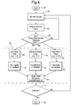
- Fig. 4 is a detailed view of the system of Fig. 2 ;
- Fig. 5 is a graphical illustration of a first example of a panic index determination according to the system of claim 2;
- Fig. 6 is a graphical illustration of a second example of a panic index determination according to the system of claim 2.
- a vehicle 10 provided with the disclosed pre-crash detection system may include a controller or processor 12, a plurality of sensors 14A, 14B, 14C, 14D, 14E, 14F and one or more controlled devices 16.
- the sensors 14A, 14B, 14C, 14D, 14E, 14F may be in communication with the processor 12 by way of communications lines 18A, 18B, 18C, 18D, 18E, 18F, which may be hard-wired, wireless or the like, to provide the processor 12 with data from the sensors 14A, 14B, 14C, 14D, 14E, 14F.
- the controlled device 16 may be any device or system capable of being controlled, such as a seatbelt pretensioner, a controlled side seat bolsters or the like.
- the processor 12 may control the controlled device 16 based upon the signals received from the sensors 14A, 14B, 14C, 14D, 14E, 14F in accordance with the disclosed pre-crash detection system.
- one aspect of the disclosed pre-crash detection system may begin at block 22.
- the system 20 may monitor signals received from the sensors 14A, 14B, 14C, 14D, 14E, 14F ( Fig. 1 ). Based upon the monitored signals, the system 20 may determine a panic index, as shown at block 26.
- the system 20 may determine whether the panic index determined at block 26 meets or exceeds a predetermined threshold value. If the determined panic index (block 26) does not meet or exceed the predetermined threshold value, the system 20 may return to block 24 to continue monitoring the signals from the sensors 14A, 14B, 14C, 14D, 14E, 14F ( Fig. 1 ).
- the system 20 may proceed to block 30 and may take any number of actions in response thereto.
- the system 20 may determine whether a collision occurred and, if no collision occurred, the system 20 may continue monitoring signals at block 24. However, if a collision did occur, the system 20 may come to an end at block 33.
- the signal monitoring step of block 24 may include monitoring various input signals 32, 34, 36, 38, 40, 42, 43, 44, 46, 48, 50, 52, 54 received from the sensors 14A, 14B, 14C, 14D, 14E, 14F ( Fig. 1 ) on the vehicle 10 ( Fig. 1 ).
- number and variety of input signals may be used to determine a panic index indicative of a crash or pre-crash state of the vehicle 10.
- any signals monitored by the vehicle 10 having a nexus with the dynamic state of the vehicle and the stability and performance of the vehicle may be useful inputs for determining a panic index.
- signals indicative of the brake pedal position 32, brake line pressure 34, vehicle speed 36 and/or other brake inputs 38 may be used to determine a braking status 56 of the vehicle 10.
- Signals indicative of the steering wheel angle 40 (or rate of change of steering wheel angle), lateral acceleration 42, yaw rate 43, vehicle speed 44 and/or other steering inputs 46 may be used to determine a steering status 58 of the vehicle 10.
- Signals indicative of the status of the automatic braking system (ABS) 48, the traction control system (TCS) 50, the vehicle stability enhancement system (VSE) 52 and/or other vehicle control and monitoring systems 54 may be used to determine a vehicle status 60 of the vehicle 10.
- the system 20 may continuously determine a panic index 64 by summing (see e.g. summation block 62) the braking status 56, the steering status 58 and vehicle status 60 of the vehicle 10.
- the system 20 may sum the values of the input signals 32, 34, 36, 38, 40, 42, 43, 44, 46, 48, 50, 52, 54 directly.
- the determination and any necessary calculations may be performed by the processor 12 ( Fig. 1 ).
- the panic index 64 which may be a numerical value, may reflect the totality of the data provided to the processor 12 by the vehicle sensors 14A, 14B, 14C, 14D, 14E, 14F ( Fig.1 ).
- each input signal 32, 34, 36, 38, 40, 42, 43, 44, 46, 48, 50, 52, 54 may have a numerical value (e.g., a magnitude or rate of change) indicative of the severity of the signal.
- a numerical value e.g., a magnitude or rate of change
- a high rate of change of brake pedal position e.g., 20 feet per second or greater
- a high rate of change of steering wheel angle e.g., 90 degrees per second or greater
- an ABS active signal e.g., a digital 1 rather than a digital 0 when the ABS is inactive
- the summation of these three panic inputs, when properly weighted or otherwise formulated, may result in a panic index of 9, for example, which may be a high panic index.
- the panic index versus time for an example vehicle 10 is shown by line D , which is a weighted sum of the vehicle speed (kph) shown by line A, the vehicle master cylinder pressure (psi) shown by line B and the vehicle deceleration (g) shown by line C.
- line D is a weighted sum of the vehicle speed (kph) shown by line A, the vehicle master cylinder pressure (psi) shown by line B and the vehicle deceleration (g) shown by line C.
- the panic index versus time for an example vehicle 10 is shown by line M, which is a weighted sum of the vehicle speed (kph) shown by line L, the master cylinder pressure (psi) shown by line J and the vehicle deceleration (g) shown by line K.
- line M is a weighted sum of the vehicle speed (kph) shown by line L, the master cylinder pressure (psi) shown by line J and the vehicle deceleration (g) shown by line K.
- the system 20 may initiate an action at block 30.
- the system 20 may prompt the processor 12 to send a control signal to the controlled device 16 such that the controlled device responds accordingly.
- the controlled device 16 may be a seatbelt pretensioner and, based upon the value of the panic index 64, the processor 12 may actuate the seatbelt pretensioner accordingly.
- the type of action taken at block 30 may be dependent upon the numerical value of the panic index 64 ( Fig. 3 ) determined at any given moment.
- various ranges of the panic index 64 may have a corresponding action associated therewith.
- the processor 12 may command the controlled device 16 to initiating a light pull of the seatbelt, as shown by block 74, and, optionally, to apply any other necessary countermeasures to prepare the vehicle 10 and its occupants for a possible collision, as shown by block 80.
- the panic index 68 is determined to be a medium value (e.g., 5-7 arbitrary units), as shown by block 70, the processor 12 may command the controlled device 16 to initiating a medium pull of the seatbelt, as shown by block 76, and, optionally, to apply any other necessary countermeasures (block 80).
- the processor 12 may command the controlled device 16 to initiating a hard pull of the seatbelt, as shown by block 78, and, optionally, to apply any other necessary countermeasures (block 80).
- the disclosed system 20 may provide a vehicle with the ability to initiate a proper response (e.g., a light pull 74, a medium pull 76 and a hard pull 78) to a crash or pre-crash condition based upon the value of the determined panic index.
- a proper response e.g., a light pull 74, a medium pull 76 and a hard pull 78
- the system 20 may determine whether a collision has occurred based upon the signals from the sensors 14A, 14B, 14C, 14D, 14E, 14F. If no collision has occurred, the system may return to block 24 and continue to monitor the signals. However, if a collision has occurred, the system 20 may reach an end point at block 33.
- the system 10 may also include an optional timing mechanism (not shown), which may be used to delay the transfer of signals to and from the controller or processor 12 for some period of time to coincide actions and countermeasures such that they occur at the same point in time or at staggered points in time.
- an optional timing mechanism (not shown), which may be used to delay the transfer of signals to and from the controller or processor 12 for some period of time to coincide actions and countermeasures such that they occur at the same point in time or at staggered points in time.
Landscapes
- Engineering & Computer Science (AREA)
- Mechanical Engineering (AREA)
- Aviation & Aerospace Engineering (AREA)
- Transportation (AREA)
- Radar, Positioning & Navigation (AREA)
- Remote Sensing (AREA)
- Automotive Seat Belt Assembly (AREA)
- Air Bags (AREA)
Applications Claiming Priority (1)
| Application Number | Priority Date | Filing Date | Title |
|---|---|---|---|
| US11/706,018 US20080191854A1 (en) | 2007-02-14 | 2007-02-14 | Low cost method of vehicle pre-crash detection |
Publications (2)
| Publication Number | Publication Date |
|---|---|
| EP1958828A2 true EP1958828A2 (de) | 2008-08-20 |
| EP1958828A3 EP1958828A3 (de) | 2011-01-19 |
Family
ID=39371020
Family Applications (1)
| Application Number | Title | Priority Date | Filing Date |
|---|---|---|---|
| EP08151059A Withdrawn EP1958828A3 (de) | 2007-02-14 | 2008-02-05 | Verfahren mit niedrigem Kostenaufwand der Vorunfalldetektion eines Fahrzeugs |
Country Status (2)
| Country | Link |
|---|---|
| US (1) | US20080191854A1 (de) |
| EP (1) | EP1958828A3 (de) |
Families Citing this family (1)
| Publication number | Priority date | Publication date | Assignee | Title |
|---|---|---|---|---|
| FR2997352B1 (fr) * | 2012-10-26 | 2016-03-25 | Dorel France Sa | Siege auto pour enfant a moyens de protection actifs |
Family Cites Families (9)
| Publication number | Priority date | Publication date | Assignee | Title |
|---|---|---|---|---|
| US5601332A (en) * | 1995-01-30 | 1997-02-11 | Hoover Universal, Inc. | Replaceable seat booster with an inflatable air cushion module |
| US6708095B2 (en) * | 2002-01-23 | 2004-03-16 | Ford Global Technologies, Llc | Method for robust occupant position control prior to vehicle impact |
| US6721659B2 (en) * | 2002-02-01 | 2004-04-13 | Ford Global Technologies, Llc | Collision warning and safety countermeasure system |
| US6519519B1 (en) * | 2002-02-01 | 2003-02-11 | Ford Global Technologies, Inc. | Passive countermeasure methods |
| JP3966161B2 (ja) * | 2002-10-31 | 2007-08-29 | 日産自動車株式会社 | 車両用シートベルト装置 |
| DE10303147A1 (de) * | 2003-01-28 | 2004-07-29 | Robert Bosch Gmbh | Verfahren zur Auslösung von Rückhaltemitteln |
| GB2412471B (en) * | 2004-03-25 | 2009-05-20 | Ford Global Tech Llc | Activation of a passive restraint system |
| JP4591750B2 (ja) * | 2004-04-26 | 2010-12-01 | アイシン精機株式会社 | 車両の乗員保護装置 |
| US7890263B2 (en) * | 2005-04-08 | 2011-02-15 | Ford Global Technologies, Llc | System and method for sensing and deployment control supervision of a safety device |
-
2007
- 2007-02-14 US US11/706,018 patent/US20080191854A1/en not_active Abandoned
-
2008
- 2008-02-05 EP EP08151059A patent/EP1958828A3/de not_active Withdrawn
Also Published As
| Publication number | Publication date |
|---|---|
| US20080191854A1 (en) | 2008-08-14 |
| EP1958828A3 (de) | 2011-01-19 |
Similar Documents
| Publication | Publication Date | Title |
|---|---|---|
| US7353905B2 (en) | Method for actuating a reversible vehicle occupant protection means in a motor vehicle | |
| JP5330521B2 (ja) | 衝突の場合における車両ブレーキ装置の調節方法 | |
| CN107521448B (zh) | 用于控制车辆的安全装置的操作的方法及控制装置 | |
| US7668633B2 (en) | Electronic control system for a vehicle and method for determining at least one driver-independent intervention in a vehicle system | |
| US7624833B2 (en) | Seat-belt pretensioner arrangement | |
| JP5197572B2 (ja) | 安全機能の作動解除のための装置及び方法 | |
| CN107972649B (zh) | 在首次撞击之后在机动车辆中提供制动辅助的方法和装置 | |
| US8244437B2 (en) | Method and system for restraint deployment using lateral kinetic energy | |
| US7894959B2 (en) | Method and device for actuating a passenger protection means | |
| US9393937B2 (en) | Method for operating a braking system of a vehicle, braking system | |
| US7954590B2 (en) | Method for a preventive-action protection system in a motor vehicle | |
| KR20110074543A (ko) | 차량 브레이크 시스템을 조정하는 방법 | |
| EP1958828A2 (de) | Verfahren mit niedrigem Kostenaufwand der Vorunfalldetektion eines Fahrzeugs | |
| JP2008508140A (ja) | 予防的に作動する保護システムを備えた自動車 | |
| US8335614B2 (en) | Method for controlling a belt pretensioner and safety arrangement comprising a belt pretensioner | |
| US8036794B2 (en) | Method and device for preventively actuating a vehicle occupant protection system | |
| JP4356400B2 (ja) | 乗員保護装置 | |
| US20080284243A1 (en) | Method for a Preventive-Action Protection System in a Motor Vehicle | |
| JP2005041255A (ja) | 乗員保護装置 | |
| CN101896377A (zh) | 用于触发车辆的人员保护装置的方法及控制装置 | |
| JP6078503B2 (ja) | 車両制動制御装置 | |
| CN110770088A (zh) | 用于操控车辆的紧急制动功能的方法和控制器 | |
| JP6166704B2 (ja) | 車両制動制御装置 | |
| JP6190766B2 (ja) | 車両制御装置 | |
| JP6167071B2 (ja) | 車両制御装置 |
Legal Events
| Date | Code | Title | Description |
|---|---|---|---|
| PUAI | Public reference made under article 153(3) epc to a published international application that has entered the european phase |
Free format text: ORIGINAL CODE: 0009012 |
|
| AK | Designated contracting states |
Kind code of ref document: A2 Designated state(s): AT BE BG CH CY CZ DE DK EE ES FI FR GB GR HR HU IE IS IT LI LT LU LV MC MT NL NO PL PT RO SE SI SK TR |
|
| AX | Request for extension of the european patent |
Extension state: AL BA MK RS |
|
| PUAL | Search report despatched |
Free format text: ORIGINAL CODE: 0009013 |
|
| AK | Designated contracting states |
Kind code of ref document: A3 Designated state(s): AT BE BG CH CY CZ DE DK EE ES FI FR GB GR HR HU IE IS IT LI LT LU LV MC MT NL NO PL PT RO SE SI SK TR |
|
| AX | Request for extension of the european patent |
Extension state: AL BA MK RS |
|
| RIC1 | Information provided on ipc code assigned before grant |
Ipc: B60R 22/195 20060101ALI20101210BHEP Ipc: B60N 2/42 20060101ALI20101210BHEP Ipc: B60L 3/00 20060101ALI20101210BHEP Ipc: B60R 21/0134 20060101AFI20080520BHEP |
|
| AKY | No designation fees paid | ||
| REG | Reference to a national code |
Ref country code: DE Ref legal event code: R108 |
|
| REG | Reference to a national code |
Ref country code: DE Ref legal event code: R108 Effective date: 20110921 |
|
| STAA | Information on the status of an ep patent application or granted ep patent |
Free format text: STATUS: THE APPLICATION IS DEEMED TO BE WITHDRAWN |
|
| 18D | Application deemed to be withdrawn |
Effective date: 20110720 |