EP1956133A1 - Haushaltgerät, insbesondere Waschmaschine, Waschtrockner oder Wäschetrockner, mit einem Blendenteil - Google Patents
Haushaltgerät, insbesondere Waschmaschine, Waschtrockner oder Wäschetrockner, mit einem Blendenteil Download PDFInfo
- Publication number
- EP1956133A1 EP1956133A1 EP08001871A EP08001871A EP1956133A1 EP 1956133 A1 EP1956133 A1 EP 1956133A1 EP 08001871 A EP08001871 A EP 08001871A EP 08001871 A EP08001871 A EP 08001871A EP 1956133 A1 EP1956133 A1 EP 1956133A1
- Authority
- EP
- European Patent Office
- Prior art keywords
- spring
- sleeve
- bushing
- household appliance
- appliance according
- Prior art date
- Legal status (The legal status is an assumption and is not a legal conclusion. Google has not performed a legal analysis and makes no representation as to the accuracy of the status listed.)
- Granted
Links
Images



Classifications
-
- D—TEXTILES; PAPER
- D06—TREATMENT OF TEXTILES OR THE LIKE; LAUNDERING; FLEXIBLE MATERIALS NOT OTHERWISE PROVIDED FOR
- D06F—LAUNDERING, DRYING, IRONING, PRESSING OR FOLDING TEXTILE ARTICLES
- D06F34/00—Details of control systems for washing machines, washer-dryers or laundry dryers
- D06F34/28—Arrangements for programme selection, e.g. control panels therefor; Arrangements for indicating programme parameters, e.g. the selected programme or its progress
Definitions
- Household appliance in particular washing machine, washer-dryer or tumble dryer, with a panel
- the invention relates to a domestic appliance, in particular a washing machine, washer-dryer or tumble dryer, with a housing, consisting of a support structure to which a front wall and a housing cover is attached, and with a diaphragm member in the intended position in the upper region by means of the housing cover on the support structure is fastened, and comprises on the bottom as a means for positioning downwardly directed pins, which are respectively inserted into sockets, which are respectively inserted in an opening in a rearwardly directed towards the device interior fold of the front wall.
- Such a household appliance is from the EP 1 621 659 A1 known.
- the household appliance disclosed in this document comprises a panel or a control panel having on the front side a substantially vertical surface with controls, which comprises on the upper side a rearwardly directed edge and at its edge above the lid on a support structure or on the housing itself is attached.
- the control panel includes fastening means directed vertically from the control panel and each projecting into an opening in a folded portion of the front wall, thus providing the positioning and mounting for the control panel.
- the connection with the front wall provides a flush transition between the front surface of the front wall and the front surface of the control panel. In the openings bushes are used, respectively, which provide an improved attachment for the pins.
- the object of the invention is to improve the attachment of a panel in a household appliance in a simple manner, with columns to be avoided.
- the achievable with the present invention consist in addition to the simple and inexpensive installation is that a very stable and reliable attachment of the panel to the front wall and the housing cover is provided, which has a very small, almost invisible gap between the panel and the adjacent housing parts, especially the front wall and the lid permanently ensures. Furthermore, a tolerance compensation is created in a simple manner without having to give a particularly high dimensional stability for the housing parts.
- the panel part is positioned over at least one spring element in the operational installation position, wherein the upper edge of the panel member is pressed against the front edge of the housing cover, wherein the spring element is arranged on or in the socket and acts on the pin. Due to the continuous force conditioning of the panel on the housing cover and subsequent deformation of the housing are reliably compensated. These and the following directions refer to the operational position of the household appliance.
- the panel part may be a part, which in particular forms the part of a control panel which is visible to the user and comprises operating and display elements for the domestic appliance.
- the cover member may also be a part of the housing, which serves as a cover.
- the socket has a first spring element which presses against the free end of the pin counter to the insertion direction, whereby the panel member is pressed up against the underside of the front edge of the housing cover.
- the socket on the opposite side of the insertion opening has a plate which is connected in the axial direction movable via at least one spring to the socket, so that the plate presses on the remote from the panel end of the pin.
- the plate here forms a spring-movable stop for the pin, which is pushed out in the inserted state against the insertion direction.
- the spring acts as a tension spring, whereby the spring action extends over a longer path.
- the socket has two opposing recesses, in each of which an acting as a spring S-shaped web is arranged.
- the bush has at least one further spring element, which presses the pin in the horizontal direction to the housing interior. In this way, with the bushing a permanent contact of the panel part is provided on the front wall and at the same time to the front edge of the housing cover.
- the second spring element is designed as a arranged in a lateral recess of the bushing leaf spring which presses against the front edge of the opening in the fold of the front wall and thereby on the socket with the inserted pin a horizontally directed to the inside of the housing force causes.
- the leaf spring can be integrally formed on the jacket of the socket, where they can be additionally provided with a detent to provide the fixation in the receiving opening and thus fulfills two functions.
- Fig. 1 is shown as a household appliance, a washing machine or a dryer in a perspective view from the front.
- the washing machine has a housing 1 which comprises a front wall 2, side walls 4 and a lid 3. Between the upper edge of the front wall 2 and the front edge of the lid 3, a panel 6 and a control panel is attached, the control and display elements 28, such as program selector, pushbuttons for special functions, lights, display and a cover 9 for a retractable Waschschein Cypruskasten or Condensate tank at the dryer, contains.
- the panel part 6 with its lower edge with the front wall 2 and with the visible rear edge with the lid 3 is substantially positively connected and connected.
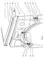
- Fig. 2 the attachment of the diaphragm part 6 is shown in an exploded perspective view.
- the front wall 2 has at the top of a directed towards the interior of the housing 1 fold 13, which is provided with openings 18. In the openings 18 sockets 19 are used.
- pins 12 are arranged, which can be inserted into the sockets 19.
- the front, substantially vertical portion 7 of the diaphragm part 6 merges on the upper side into a substantially horizontal section 8.
- a groove 26 is formed, in which a mounted on the front edge of the housing cover 3 spring 27 can be inserted.
- the panel part 6 is fastened to the front wall 2 via the pins 12 inserted in the sockets 19, the upper side 8 of the panel part 6 being fixed over the housing cover 3 placed on the support structure.
- the side walls 4 and rear wall (not shown) or alternatively a support frame (not shown) may be used.
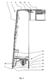
- the panel part 6 is shown in the mounted or installed state, wherein the front visible surface 7 of the panel part 6 is flush with the outer surface 5 of the front wall 2 and passes into this.
- pins 12 can be seen as fasteners, which are aligned on the underside of the panel 6 in the intended position or use of the household appliance down.
- the pins 12 are arranged or formed on a web 10, which ensures a positioning of the pin 12 offset from the outer, front surface 7 of the panel part.
- the front wall 2 contains in the upper region at least one approximately at right angles to the rear towards the device interior directed bevel 13, in which the receiving openings 18 (FIG. Fig. 2 ) are arranged for the sockets 19.
- the fold 13 may comprise several sections, wherein the division into three sections has proved to be expedient.
- the first section 15 is directed approximately at right angles to the rear to the interior of the device and executed with a gentle curvature 14 arcuate.
- the second section 16 connects, which is directed approximately at right angles to the top.
- the third section 17, which is directed approximately at right angles to the rear of the device interior.
- the lower edge of the panel 6 has a groove 29 (FIG. Fig. 4 ), which rests on the arcuate portion 14 on the first portion 15 of the fold 13.
- the diaphragm part 6 relative to the curved portion 14 can be slightly displaced, with always a flush, at least almost flush transition between the front wall 2 and the front surface 7 of the diaphragm part. 6 provided.
- the attachment of the panel member 6 takes place on the top of the lid 3 to the support structure.
- the panel member 6 at its upper wall 8 at the rear end a shaped groove 26 into which engages a cover 3 arranged on the corresponding spring 27 in the mounted state.
- the lid 3 is attached to the supporting structure, for example the side walls 4 (FIG. Fig. 1 ) or a frame part (not visible) attached.
- a support structure here, for example, a frame assembly with vertical corner profiles and crossbeams can be used for stabilization.
- the bushings 19 are designed so that they press the panel member 6 up against the front edge of the lid 3. With this measure, the spring 27 attached to the housing cover 3 remains securely in the groove 26 which is located on the upper side 8 of the diaphragm part 6. By avoiding the gap, the ingress of dirt or spray into the interior of the housing 1 is prevented. Furthermore, noises that penetrate from the inside of the machine, as well as rattling noises or vibrations are avoided.
- the bush 19 comprises a spring element which presses on the free end of the pin 12 and presses it in the direction V, counter to the insertion direction. The resilient property is dimensioned so that it acts over the entire life of the household appliance.
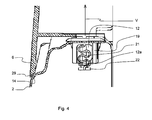
- Fig. 4 the attachment or the connection between the panel 6 and the front wall 2 is shown in detail.
- the pin 12 protrudes into the socket 19, wherein the free end 12a presses against a plate 22 which is resiliently mounted on the sleeve 19 via an S-shaped web 21.
- the resilient attachment of the plate 22 is designed so that the spring, which is provided by the S-shaped web 21, is tensioned when the plate 22 is moved over the inserted pin 12 from its rest position in the opposite direction V.
- the socket 19 is shown as a single part in a perspective view.
- the bush 19 in its casing 20 contains at least one Recess 30, in which the S-shaped web 21 is inserted or molded.
- the S-shaped web 21 is cut out of the material of the jacket 20.
- the web 21 is connected to the remaining remaining material of the sleeve 19.
- the plate 22 is attached to the S-shaped web 21, which has a movable stop for the pin 12 (FIG. Fig. 6 ) when it is introduced.
- locking means are further provided, which fix the bushing 19 in the receiving opening 18 (FIG. Fig. 2 ) or secure them against falling out.
- latching means at least one leaf spring 23 is provided, which is formed as a C-shaped cutout 24 from the shell 20 and has an outwardly directed latching lug 25 for latching with the edge of the receiving opening 18.
- the leaf spring 23 is connected on the side remote from the journal insertion with the material of the shell 20 and has its center of rotation in this area.
- the leaf spring 23 has at the free end an extension 23a, which presses in the inserted state on one side on the inner opening edge of the receiving opening 18 and causes a resilient displacement of the sleeve 19 within the receiving opening 18.
- Fig. 6 the inserted into the receiving opening 18 bushing 19 is shown with pin 12 in detail.
- the extension 23a presses against the front opening edge of the receiving opening 18, whereby the bushing 19 is displaced substantially horizontally in the direction H to the device interior.
- the locking lugs 25 are below the opening edge of the fold 13 and provide the support of the bushing 19 in the receiving opening 18.
- the pin 12 located in the socket 19 is pressed in the direction V upwards against the insertion direction.
- the shutter 6 can now be moved slightly upwards in the direction V.
- the lower edge By acting in the direction H force of the bushing 19, the lower edge is pressed with the overhang 11 and the groove 29 against the front wall 2 and against the curvature 14 for the fold 13, whereby a too large gap between the panel 6 and front wall 2 avoided becomes.
- Another possibility is to insert the bushing 19 firmly in the receiving opening 18 and to press the panel part 6 with the groove 29 at the lower edge to provide a bias against the front wall 2 and against the curved portion 14.
Landscapes
- Engineering & Computer Science (AREA)
- Textile Engineering (AREA)
- Detail Structures Of Washing Machines And Dryers (AREA)
- Main Body Construction Of Washing Machines And Laundry Dryers (AREA)
Abstract
Description
- Haushaltgerät, insbesondere Waschmaschine, Waschtrockner oder Wäschetrockner, mit einem Blendenteil
- Die Erfindung betrifft ein Haushaltgerät, insbesondere Waschmaschine, Waschtrockner oder Wäschetrockner, mit einem Gehäuse, bestehend aus einer Tragstruktur, an welcher eine Frontwand und ein Gehäusedeckel befestigt ist, und mit einem Blendenteil, das in bestimmungsgemäßer Lage im oberen Bereich mittels des Gehäusedeckels an der Tragstruktur befestigt ist, und auf der Unterseite als Mittel für die Positionierung nach unten gerichtete Zapfen umfasst, die jeweils in Buchsen eingesetzt sind, die jeweils in einer Öffnung in einer nach hinten zum Geräteinneren gerichteten Abkantung der Frontwand eingesteckt sind.
- Ein solches Haushaltgerät ist aus der
EP 1 621 659 A1 bekannt. Das in dieser Schrift offenbarte Haushaltgerät enthält ein Blendenteil bzw. eine Bedienblende, die auf der Frontseite eine im Wesentlichen senkrechte Fläche mit Bedienelementen besitzt, die auf der Oberseite eine nach hinten gerichtete Abkantung umfasst und an ihrem Rand über dem Deckel an einer Tragstruktur oder am Gehäuse selbst befestigt ist. An der Unterseite enthält die Bedienblende Befestigungsmittel, die vertikal von der Bedienblende wegweisend gerichtet sind und jeweils in eine Öffnung in einem abgekanteten Abschnitt der Frontwand ragen, so dass damit die Positionierung und Befestigung für die Bedienblende bereitgestellt wird. Durch die Verbindung mit der Frontwand wird ein bündiger Übergang zwischen der Frontfläche der Frontwand und der Frontfläche der Bedienblende bereitgestellt. In den Öffnungen sind jeweils Buchsen eingesetzt, die eine verbesserte Befestigung für die Zapfen bereitstellen. Bei der Herstellung von Gehäuseteilen lassen sich in der Regel Toleranzen hinsichtlich der Maßhaltigkeit nicht vermeiden. Deshalb können an den Übergangsstellen Spalten entstehen, die an zugänglichen Stellen häufig als störend empfunden werden bzw. die Dichtigkeit gegen Spritzwasser vermindern. Bei einer Bedienblende, die mit ihrer Oberseite nahezu bündig mit der Fläche des Deckels angeordnet ist, kann es passieren, dass ein Spalt zwischen der Oberseite des Gehäuses entsteht. - Aus der
DE 10 2005 025 808 B3 ist es bekannt, bei einem flach geneigten Blendenteil Federn zu verwenden, die den hinteren Teil gegen den Rand des aufliegenden Gehäusedeckels drücken. Hierzu werden als Blattfeder konzipierte Federelemente verwendet, die zwischen dem unteren Gehäuseteil, dem Blendenteil und dem darunter liegenden Rahmenteil eingelegt werden. Durch den aufgelegten Gehäusedeckel wird der hintere Rand des Blendenteils gegen die Federkraft nach unten gegen das Rahmenteil gedrückt, wodurch das Blendenteil unter ständigem Druck mit seinem hinteren Rand am Gehäusedeckel anliegt. Die Richtungsangaben beziehen sich auf die bestimmungsgemäße Aufstell-, oder Betriebssituation des Haushaltgerätes. Die Verwendung der zusätzlichen Federn ist recht aufwändig, da eine Vielzahl von einzelnen Teilen montiert werden muss. Ferner ist es notwendig, dass sich unterhalb des Blendenteils ein geeignetes Rahmenteil zur Abstützung der Federn befindet. - Die Aufgabe der Erfindung ist, die Befestigung eines Blendenteils in einem Haushaltgerät auf einfache Weise zu verbessern, wobei Spalten vermieden werden sollen.
- Erfindungsgemäß wird diese Aufgabe durch ein Haushaltgerät mit einem Blendenteil mit den Merkmalen des Patentanspruchs 1 gelöst. Vorteilhafte Ausgestaltungen und Weiterbildungen der Erfindung ergeben sich aus den nachfolgenden abhängigen Ansprüchen.
- Die mit der Erfindung erreichbaren Vorteile bestehen neben der einfachen und kostengünstigen Montage darin, dass eine sehr stabile und zuverlässige Befestigung des Blendenteils an der Frontwand und dem Gehäusedeckel bereitgestellt wird, die einen sehr kleinen, nahezu nicht sichtbaren Spalt zwischen dem Blendenteil und den angrenzenden Gehäuseteilen, insbesondere der Frontwand und dem Deckel dauerhaft sicherstellt. Ferner wird auf einfache Weise ein Toleranzausgleich geschaffen, ohne dass eine besonders hohe Maßhaltigkeit für die Gehäuseteile gegeben sein muss.
- Hierzu wird das Blendenteil über zumindest ein Federelement in die betriebsgemäße Einbaulage positioniert, wobei der obere Rand des Blendenteils gegen den vorderen Rand des Gehäusedeckels gedrückt wird, wobei das Federelement an oder in der Buchse angeordnet ist und auf den Zapfen wirkt. Durch die andauernde kraftmäßige Anlage des Blendenteils am Gehäusedeckel werden auch nachträgliche Verformungen des Gehäuses zuverlässig ausgeglichen. Diese und die nachfolgenden Richtungsangaben beziehen sich auf die betriebsgemäße Lage des Haushaltgerätes. Das Blendenteil kann ein Teil sein, welches insbesondere den für den Benutzer sichtbaren Teil einer Bedienblende bildet und Bedien- und Anzeigeelemente für das Haushaltgerät umfasst. Das Blendenteil kann auch ein Teil des Gehäuses sein, welches als Abdeckung dient.
- In einer vorteilhaften Ausführungsform besitzt die Buchse ein erstes Federelement, welches auf das freie Ende des Zapfen entgegen der Einsteckrichtung drückt, wodurch das Blendenteil nach oben gegen die Unterseite des vorderen Randes des Gehäusedeckels gedrückt wird.
- Es ist hierbei zweckmäßig, ein erstes Federelement einstückig an der Buchse anzuformen. Auf diese Weise ist insbesondere bei Buchsen aus Kunststoffmaterial das Federelement sehr einfach und ohne zusätzliche Einzelteile bereitzustellen.
- In einer weiteren Ausführung besitzt die Buchse an der gegenüberliegenden Seite der Einführöffnung eine Platte, die in axialer Richtung beweglich über zumindest eine Feder mit der Buchse verbunden ist, so dass die Platte auf das von dem Blendenteil entfernte Ende des Zapfens drückt. Die Platte bildet hierbei einen federbeweglichen Anschlag für den Zapfen, der im eingesteckten Zustand entgegen der Einsteckrichtung herausgedrückt wird. Die Feder wirkt hierbei als Zugfeder, wodurch sich die Federwirkung über einen längeren Weg erstreckt.
- In einer weiteren, zweckmäßigen Ausführung besitzt die Buchse zwei sich gegenüberliegende Aussparungen, in denen jeweils ein als Feder wirkender S-förmiger Steg angeordnet ist. Damit wird eine stabile Befestigung der Platte an den Stegen bereitgestellt und eine gleichmäßige Federwirkung auf die Platte bzw. auf den eingeführten Zapfen erreicht. Unerwünschtes Verkanten wird somit vermieden.
- In einer weiteren Ausführung besitzt die Buchse zumindest ein weiteres Federelement, welches den Zapfen in horizontaler Richtung zum Gehäuseinneren drückt. Auf diese Weise wird mit der Buchse eine dauerhafte Anlage des Blendenteils an der Frontwand und gleichzeitig an den vorderen Rand des Gehäusedeckels bereitgestellt.
- In einer vorteilhaften Weiterbildung ist das zweite Federelement als eine in einer seitlichen Aussparung der Buchse angeordnete Blattfeder ausgeführt, die gegen den vorderen Rand der Öffnung in der Abkantung der Frontwand drückt und dadurch auf die Buchse mit dem eingesteckten Zapfen eine horizontal zur Innenseite des Gehäuses gerichtete Kraft bewirkt. Auf diese Weise kann die Blattfeder einstückig an dem Mantel der Buchse angeformt werden, wobei sie zusätzlich mit einer Rastnase versehen werden kann, um die Fixierung in der Aufnahmeöffnung bereitzustellen und somit zwei Funktionen erfüllt.
- Ein Ausführungsbeispiel der Erfindung ist in den Zeichnungen schematisch dargestellt und wird nachfolgend näher beschrieben. Es zeigen:
- Fig. 1
- eine Waschmaschine oder einen Trockner mit einem Blendenteil in der Vorderansicht;
- Fig. 2
- in einer detaillierten Explosionsdarstellung den Bereich des Blendenteils;
- Fig. 3
- das Blendenteil in einer Seitenansicht als Schnittdarstellung im montierten Zustand;
- Fig. 4
- den Befestigungsbereich des Blendenteils im Detail;
- Fig. 5
- die Buchse in einer perspektivischen Ansicht und
- Fig. 6
- den Befestigungsbereich des Blendenteils in einer detaillierten Schnittansicht.
- In
Fig. 1 ist als Haushaltgerät eine Waschmaschine oder ein Trockner in einer perspektivischen Ansicht von vorn dargestellt. Die Waschmaschine besitzt ein Gehäuse 1, welches eine Frontwand 2, Seitenwände 4 und einen Deckel 3 umfasst. Zwischen dem oberen Rand der Frontwand 2 und dem vorderen Rand des Deckels 3 ist ein Blendenteil 6 bzw. eine Bedienblende angebracht, die Bedien- und Anzeigeelemente 28, wie Programmwahlschalter, Drucktasten für Sonderfunktionen, Leuchtanzeigen, Display sowie eine Abdeckung 9 für einen ausziehbaren Waschmitteleinspülkasten oder Kondensatsammelbehälter beim Trockner, enthält. Hierbei ist das Blendenteil 6 mit seinem unteren Rand mit der Frontwand 2 und mit dem sichtbaren hinteren Rand mit dem Deckel 3 im Wesentlichen formschlüssig und verbunden. - In
Fig. 2 ist die Befestigung des Blendenteils 6 in einer perspektivischen Explosionsansicht dargestellt. Die Frontwand 2 besitzt am oberen Rand eine zum Inneren des Gehäuses 1 gerichtete Abkantung 13, die mit Öffnungen 18 versehen ist. In die Öffnungen 18 werden Buchsen 19 eingesetzt. An der Unterseite des Blendenteils 6 sind Zapfen 12 angeordnet, die in die Buchsen 19 einsteckbar sind. Der vordere, im Wesentlichen vertikale Abschnitt 7 des Blendenteils 6 geht auf der Oberseite in einen im Wesentlichen horizontalen Abschnitt 8 über. Am hinteren Ende des horizontalen Abschnitts 8 ist eine Nut 26 angeformt, in die eine am vorderen Rand des Gehäusedeckels 3 angebrachte Feder 27 einführbar ist. Das bedeutet, dass das Blendenteil 6 über die in die Buchsen 19 eingesteckten Zapfen 12 an der Frontwand 2 befestigt ist, wobei die Oberseite 8 des Blendenteils 6 über den auf die Tragstruktur aufgelegten Gehäusedeckel 3 fixiert wird. Als Tragstruktur können die Seitenwände 4 und Rückwand (nicht dargestellt) oder alternativ ein Tragrahmen (nicht dargestellt) verwendet werden. - In der
Fig. 3 ist das Blendenteil 6 im befestigten bzw. eingebauten Zustand dargestellt, wobei die vordere sichtbare Fläche 7 des Blendenteils 6 bündig zur äußeren Fläche 5 der Frontwand 2 steht bzw. in diese übergeht. In dieser Darstellung sind als Befestigungsmittel Zapfen 12 zu erkennen, die auf der Unterseite des Blendenteils 6 in bestimmungsgemäßer Lage oder Verwendung des Haushaltgerätes nach unten ausgerichtet sind. Hierbei sind die Zapfen 12 an einem Steg 10 angeordnet bzw. angeformt, der eine Positionierung der Zapfen 12 versetzt gegenüber der äußeren, vorderen Fläche 7 des Blendenteils gewährleistet. Die Frontwand 2 enthält im oberen Bereich zumindest eine in etwa im rechten Winkel nach hinten zum Geräteinneren gerichtete Abkantung 13, in der die Aufnahmeöffnungen 18 (Fig. 2 ) für die Buchsen 19 angeordnet sind. Die Abkantung 13 kann mehrere Abschnitte umfassen, wobei sich die Aufteilung in drei Abschnitte als zweckmäßig erwiesen hat. Der erste Abschnitt 15 ist in etwa im rechten Winkel nach hinten zum Geräteinneren gerichtet und mit einer sanften Krümmung 14 bogenförmig ausgeführt. Von diesem ersten Abschnitt 15 ausgehend schließt sich der zweite Abschnitt 16 an, der in etwa im rechten Winkel nach oben gerichtet ist. Von diesem ausgehend beginnt der dritte Abschnitt 17, der in etwa im rechten Winkel nach hinten zum Geräteinneren gerichtet ist. Die untere Kante des Blendenteils 6 hat eine Hohlkehle 29 (Fig. 4 ), die auf dem bogenförmigen Abschnitt 14 am ersten Abschnitt 15 der Abkantung 13 aufliegt. Durch die bogenförmige Ausgestaltung 18 der Kante und der Hohlkehle 29 am unteren Rand des Blendenteils 6 kann das Blendenteil 6 gegenüber dem gekrümmten Abschnitt 14 geringfügig verschoben werden, wobei stets ein bündiger, zumindest nahezu bündiger Übergang zwischen Frontwand 2 und der vorderen Fläche 7 des Blendenteils 6 bereitgestellt wird. - Wie in
Fig. 3 ferner dargestellt, erfolgt die Befestigung des Blendenteils 6 auf der Oberseite über den Deckel 3 an die Tragstruktur. Hierbei weist das Blendenteil 6 an ihrer oberen Wandung 8 am hinteren Ende eine ausgeformte Nut 26 auf, in die eine am Deckel 3 korrespondierend angeordnete Feder 27 im montierten Zustand eingreift. Der Deckel 3 wird an der Tragstruktur, beispielsweise den Seitenwänden 4 (Fig. 1 ) oder einem Rahmenteil (nicht sichtbar) befestigt. Dadurch wird trotz einfacher Montage eine zuverlässige, feste und gegenüber der Frontwand 2 formschlüssige und flächig bündige Verbindung des Blendenteils 6 erreicht. Als Tragstruktur kann hierbei beispielsweise eine Rahmenanordnung mit vertikalen Eckprofilen und Quertraversen zur Stabilisierung verwendet werden. Aufgrund von Toleranzen oder Materialermüdungen kann es vorkommen, dass zwischen dem vorderen Rand des Gehäusedeckels 3 und der oberen Fläche 8 des Blendenteils 6 ein Spalt entsteht. Um das zu vermeiden, sind die Buchsen 19 so ausgeführt, dass sie das Blendenteil 6 nach oben gegen den vorderen Rand des Deckels 3 drücken. Mit dieser Maßnahme verbleibt die am Gehäusedeckel 3 angebrachte Feder 27 sicher in der Nut 26, die sich auf der Oberseite 8 des Blendenteils 6 befindet. Durch die Vermeidung des Spaltes wird das Eindringen von Schmutz oder Spritzwasser in das Innere des Gehäuses 1 verhindert. Ferner werden Geräusche, die aus dem Inneren der Maschine dringen, sowie Klappergeräusche oder Vibrationen vermieden. Die Buchse 19 umfasst hierzu ein Federelement, welches auf das freie Ende des Zapfens 12 drückt und diesen in Richtung V, entgegen der Einsteckrichtung, drückt. Die federnde Eigenschaft ist so dimensioniert, dass sie über die gesamte Lebensdauer des Haushaltgerätes wirkt. - In
Fig. 4 ist die Befestigung bzw. die Verbindung zwischen Blendenteil 6 und Frontwand 2 im Detail dargestellt. Der Zapfen 12 ragt hierbei in die Buchse 19, wobei das freie Ende 12a gegen eine Platte 22 drückt, die über einen S-förmigen Steg 21 federnd an der Buchse19 angebracht ist. Die federnde Anbringung der Platte 22 ist so ausgeführt, dass die Feder, die durch den S-förmigen Steg 21 bereitgestellt wird, gespannt wird, wenn die Platte 22 über den eingeführten Zapfen 12 aus ihrer Ruheposition heraus entgegen Richtung V bewegt wird. - In
Fig. 5 ist die Buchse 19 als Einzelteil in einer perspektivischen Ansicht dargestellt. Zur Bereitstellung des S-förmigen Steges 21 enthält die Buchse19 in ihrem Mantel 20 zumindest eine Aussparung 30, in die der S-förmige Steg 21 eingefügt bzw. eingeformt ist. In einer bevorzugten Ausführung ist der S-förmige Steg 21 aus dem Material des Mantels 20 herausgeschnitten. An der Seite der Einführung für den Zapfen 12 (Fig. 6 ) ist der Steg 21 mit dem restlichen verbleibenden Material der Buchse 19 verbunden. Auf der von der Einführung entfernten Seite ist am S-förmigen Steg 21 die Platte 22 angebracht, die einen beweglichen Anschlag für den Zapfen 12 (Fig. 6 ) bereitstellt, wenn dieser eingeführt ist. - Im Mantel 20 sind ferner Rastmittel vorgesehen, die die Fixierung der Buchse 19 in der Aufnahmeöffnung 18 (
Fig. 2 ) bereitstellen bzw. diese gegen Herausfallen sichern. Als Rastmittel ist zumindest eine Blattfeder 23 vorgesehen, die als c-förmiger Ausschnitt 24 aus dem Mantel 20 gebildet ist und eine nach außen gerichtete Rastnase 25 zur Verrastung mit dem Rand der Aufnahmeöffnung 18 besitzt. Die Blattfeder 23 ist auf der von der Zapfeneinführung entfernten Seite mit dem Material des Mantels 20 verbunden und hat in diesem Bereich ihren Drehpunkt. Die Blattfeder 23 hat am freien Ende eine Fortsatz 23a, der im eingesetzten Zustand einseitig auf den inneren Öffnungsrand der Aufnahmeöffnung 18 drückt und eine federelastische Verschiebung der Buchse 19 innerhalb der Aufnahmeöffnung 18 bewirkt. - In
Fig. 6 ist die in die Aufnahmeöffnung 18 eingesetzte Buchse 19 mit Zapfen 12 im Detail dargestellt. Hierbei drückt der Fortsatz 23a gegen den vorderen Öffnungsrand der Aufnahmeöffnung 18, wodurch die Buchse 19 im Wesentlichen horizontal in Richtung H zum Geräteinneren verschoben wird. Die Rastnasen 25 liegen unterhalb des Öffnungsrandes an der Abkantung 13 und bieten den Halt der Buchse 19 in der Aufnahmeöffnung 18. Gleichzeitig wird der in der Buchse 19 befindliche Zapfen 12 in Richtung V nach oben entgegen der Einsteckrichtung gedrückt. Im Falle des Toleranzausgleiches kann nun das Blendenteil 6 etwas nach oben in Richtung V bewegt werden. Durch die in Richtung H wirkende Kraft der Buchse 19 wird der untere Rand mit der Überkragung 11 und der Hohlkehle 29 gegen die Frontwand 2 bzw. gegen die Krümmung 14 für die Abkantung 13 gedrückt, wodurch ein zu großer Spalt zwischen Blendenteil 6 und Frontwand 2 vermieden wird. Eine andere Möglichkeit ist, die Buchse 19 fest in der Aufnahmeöffnung 18 einzusetzen und das Blendenteil 6 mit der Hohlkehle 29 am unteren Rand unter Bereitstellung einer Vorspannung gegen die Frontwand 2 bzw. gegen den gekrümmten Abschnitt 14 zu drücken. -
- 1:
- Gehäuse
- 2:
- Frontwand
- 3:
- Deckel
- 4:
- Seitenwände / Tragstruktur
- 5:
- Äußere Fläche der Frontwand
- 6:
- Bedienblende
- 7:
- Frontfläche der Bedienblende
- 8:
- obere Fläche der Bedienblende
- 9:
- Abdeckung für Waschmittelspülkasten
- 10:
- Steg
- 11:
- Überkragung
- 12:
- Zapfen
- 13:
- Abkantung
- 14:
- sanfte Krümmung
- 15:
- erster Abschnitt
- 16:
- zweiter Abschnitt
- 17:
- dritter Abschnitt
- 18:
- Aufnahmeöffnung
- 19:
- Buchse
- 20:
- Mantel
- 21
- S-Steg
- 22:
- Platte
- 23:
- Blattfeder
- 23a:
- Fortsatz
- 24:
- c-Ausschnitt
- 25:
- Rastnase
- 26:
- Nut in der Bedienblende
- 27:
- Feder
- 28:
- Bedienelemente
- 28a:
- Anzeigeelemente
- 29:
- Hohlkehle
- 30:
- Aussparung
- H:
- Horizontale Richtung
- V:
- Vertikale Richtung
Claims (8)
- Haushaltgerät, insbesondere Waschmaschine, Waschtrockner oder Wäschetrockner, mit einem Gehäuse (1), bestehend aus einer Tragstruktur (4), an welcher eine Frontwand (2) und ein Gehäusedeckel (3) befestigt ist, und mit einem Blendenteil (6), das in bestimmungsgemäßer Lage im oberen Bereich mittels des Gehäusedeckels (6) an der Tragstruktur (4) befestigt ist, und auf der Unterseite als Mittel für die Positionierung nach unten gerichtete Zapfen (12) umfasst, die jeweils in Buchsen (19) eingesetzt sind, die jeweils in einer Öffnung (18) in einer nach hinten zum Geräteinneren gerichteten Abkantung (13) der Frontwand (2) eingesteckt sind,
dadurch gekennzeichnet,
dass das Blendenteil (6) über zumindest ein Federelement (21, 23) in die betriebsgemäße Einbaulage positioniert wird, wobei der obere Rand des Blendenteils (6) gegen den vorderen Rand des Gehäusedeckels (3) gedrückt wird, wobei das Federelement (21, 23) an oder in der Buchse (19) angeordnet ist und auf den Zapfen (12) wirkt. - Haushaltgerät nach Anspruch 1,
dadurch gekennzeichnet,
dass die Buchse (19) ein erstes Federelement (21) besitzt, welches auf das freie Ende des Zapfen (12) entgegen der Einsteckrichtung drückt, wodurch das Blendenteil (6) nach oben gegen die Unterseite des vorderen Randes des Gehäusedeckels (3) gedrückt wird. - Haushaltgerät nach Anspruch 2,
dadurch gekennzeichnet,
dass das erste Federelement (21) einstückig an der Buchse (19) angeformt ist. - Haushaltgerät nach Anspruch 2,
dadurch gekennzeichnet,
dass die Buchse (19) an der gegenüberliegenden Seite der Einführöffnung eine Platte (22) besitzt, die in axialer Richtung (V) beweglich über zumindest eine Feder (21) mit der Buchse (19) verbunden ist, so dass die Platte (22) auf das freie Ende des Zapfens (19) drückt, wobei die Feder (21) als Zugfeder ausgebildet ist. - Haushaltgerät nach Anspruch 3,
dadurch gekennzeichnet,
dass die zumindest eine Feder ein S-förmiger Steg (21) ist, der in einer seitlichen Aussparung (30) der Buchse (19) angeordnet ist. - Haushaltgerät nach Anspruch 3 oder 4,
dadurch gekennzeichnet,
dass die Buchse (19) zwei sich gegenüberliegende Aussparungen (30) besitzt, in denen jeweils ein als Feder wirkender S-förmiger Steg (21) angeordnet ist. - Haushaltgerät nach Anspruch 1,
dadurch gekennzeichnet,
dass die Buchse (19) zumindest ein weiteres Federelement (23) besitzt, welches den Zapfen (12) in horizontaler Richtung (H) zum Gehäuseinneren drückt. - Haushaltgerät nach Anspruch 7,
dadurch gekennzeichnet,
dass das zweite Federelement (23) als c-förmiger Ausschnitt (24) aus dem Mantel (20) der Buchse (19) gebildet ist und als Blattfeder (23) wirkt, die gegen den vorderen Rand der Aufnahmeöffnung (18) in der Abkantung (13) der Frontwand (2) drückt und dadurch auf die Buchse (19) mit dem eingesteckten Zapfen (12) eine horizontal zur Innenseite des Gehäuses gerichtete Kraft (H) bewirkt.
Applications Claiming Priority (1)
| Application Number | Priority Date | Filing Date | Title |
|---|---|---|---|
| DE102007007390A DE102007007390B3 (de) | 2007-02-12 | 2007-02-12 | Haushaltgerät, insbesondere Waschmaschine, Waschtrockner oder Wäschetrockner, mit einem Blendenteil |
Publications (2)
| Publication Number | Publication Date |
|---|---|
| EP1956133A1 true EP1956133A1 (de) | 2008-08-13 |
| EP1956133B1 EP1956133B1 (de) | 2009-08-12 |
Family
ID=38955164
Family Applications (1)
| Application Number | Title | Priority Date | Filing Date |
|---|---|---|---|
| EP08001871A Not-in-force EP1956133B1 (de) | 2007-02-12 | 2008-02-01 | Haushaltgerät, insbesondere Waschmaschine, Waschtrockner oder Wäschetrockner, mit einem Blendenteil |
Country Status (3)
| Country | Link |
|---|---|
| EP (1) | EP1956133B1 (de) |
| AT (1) | ATE439466T1 (de) |
| DE (2) | DE102007007390B3 (de) |
Cited By (1)
| Publication number | Priority date | Publication date | Assignee | Title |
|---|---|---|---|---|
| EP3954822A1 (de) * | 2020-08-11 | 2022-02-16 | LG Electronics Inc. | Wäschebehandlungsvorrichtung mit einer bedienblende |
Families Citing this family (2)
| Publication number | Priority date | Publication date | Assignee | Title |
|---|---|---|---|---|
| DE102009007531B4 (de) * | 2009-02-04 | 2013-08-01 | Miele & Cie. Kg | Gehäuse für eine Wäschebehandlungsmaschine oder Spülmaschine |
| EP2672000B1 (de) * | 2012-06-05 | 2015-01-21 | Miele & Cie. KG | Wäschetrockner |
Citations (3)
| Publication number | Priority date | Publication date | Assignee | Title |
|---|---|---|---|---|
| US20050178164A1 (en) | 2004-02-13 | 2005-08-18 | Kim Jae K. | Control panel assembly for washing machine |
| EP1621659A1 (de) * | 2004-07-26 | 2006-02-01 | Miele & Cie. KG | Haushaltgerät, insbesondere Wäschebehandlungsmachine wie Waschmaschine, Waschtrockner oder Wäschetrockner, mit einer Bedienblende und Verfahren zur Montage einer Bedienblende |
| DE102005025808B3 (de) * | 2005-06-02 | 2006-08-03 | Miele & Cie. Kg | Frontbeladbares Wäschebehandlungsgerät mit einer Bedienblende |
-
2007
- 2007-02-12 DE DE102007007390A patent/DE102007007390B3/de not_active Expired - Fee Related
-
2008
- 2008-02-01 DE DE502008000071T patent/DE502008000071D1/de active Active
- 2008-02-01 EP EP08001871A patent/EP1956133B1/de not_active Not-in-force
- 2008-02-01 AT AT08001871T patent/ATE439466T1/de active
Patent Citations (3)
| Publication number | Priority date | Publication date | Assignee | Title |
|---|---|---|---|---|
| US20050178164A1 (en) | 2004-02-13 | 2005-08-18 | Kim Jae K. | Control panel assembly for washing machine |
| EP1621659A1 (de) * | 2004-07-26 | 2006-02-01 | Miele & Cie. KG | Haushaltgerät, insbesondere Wäschebehandlungsmachine wie Waschmaschine, Waschtrockner oder Wäschetrockner, mit einer Bedienblende und Verfahren zur Montage einer Bedienblende |
| DE102005025808B3 (de) * | 2005-06-02 | 2006-08-03 | Miele & Cie. Kg | Frontbeladbares Wäschebehandlungsgerät mit einer Bedienblende |
Cited By (4)
| Publication number | Priority date | Publication date | Assignee | Title |
|---|---|---|---|---|
| EP3954822A1 (de) * | 2020-08-11 | 2022-02-16 | LG Electronics Inc. | Wäschebehandlungsvorrichtung mit einer bedienblende |
| CN114075754A (zh) * | 2020-08-11 | 2022-02-22 | Lg电子株式会社 | 衣物处理装置 |
| US11873597B2 (en) | 2020-08-11 | 2024-01-16 | Lg Electronics Inc. | Laundry treating apparatus |
| CN114075754B (zh) * | 2020-08-11 | 2024-03-08 | Lg电子株式会社 | 衣物处理装置 |
Also Published As
| Publication number | Publication date |
|---|---|
| DE502008000071D1 (de) | 2009-09-24 |
| ATE439466T1 (de) | 2009-08-15 |
| EP1956133B1 (de) | 2009-08-12 |
| DE102007007390B3 (de) | 2008-02-21 |
Similar Documents
| Publication | Publication Date | Title |
|---|---|---|
| EP3973126B1 (de) | Möbelbeschlag | |
| EP1806447B1 (de) | Gehäuse für eine frontbeschickbare Wäschebehandlungsmaschine | |
| DE102019113337B4 (de) | Möbelbeschlag | |
| EP3094212B1 (de) | Schwenkgelenk und möbelstück mit einem solchen | |
| EP4112854A1 (de) | Beschlaganordnung | |
| EP0917514B1 (de) | Elastische lagerung eines hydraulischen aggregates einer fahrzeugbremsanlage | |
| AT401667B (de) | Möbelscharnier mit schliessmechanismus | |
| AT524392A1 (de) | Möbelbeschlag mit mindestens einem Drehhebel und mindestens einem Lagerstift | |
| EP1956133B1 (de) | Haushaltgerät, insbesondere Waschmaschine, Waschtrockner oder Wäschetrockner, mit einem Blendenteil | |
| EP2633537B1 (de) | Schlüsselkartenschalter | |
| EP2059147A1 (de) | Verbindungseinrichtung an einem schubkasten | |
| EP3884554B1 (de) | Elektrisches installationsgerät | |
| EP2045405B1 (de) | Betätigungsplatte für eine Betätigungsvorrichtung einer Spüleinrichtung | |
| EP1790251A1 (de) | Möbel oder Haushaltsgerät mit einem Einschubteil | |
| DE102005011046B3 (de) | Schubladenartig verschiebbares Bauteil, wie Waschmitteleinspülkasten oder Kondensatsammelbehälter für ein Haushaltgerät wie Waschmaschine, Wäschetrockner oder Waschtrockner | |
| EP1621659B1 (de) | Haushaltgerät, insbesondere Wäschebehandlungsmachine wie Waschmaschine, Waschtrockner oder Wäschetrockner, mit einer Bedienblende. | |
| EP0730077B1 (de) | Haubenhalter an Abdeckhauben für Türschliessergehäuse | |
| DE69614117T2 (de) | Schaltermechanismus | |
| DD297933A5 (de) | Tastenelement mit daempfungsfedern | |
| DE102005025808B3 (de) | Frontbeladbares Wäschebehandlungsgerät mit einer Bedienblende | |
| WO2009132749A1 (de) | Befestigungsklammer sowie anordnung mit einer befestigungssklammer und mit einem anbauteil | |
| WO2006079571A1 (de) | Schubkasten mit zwei seitenzargen und mit einer blende | |
| DE102008026128A1 (de) | Scharnier für Dunstabzugshaube und Dunstabzugshaube | |
| DE102006032943B4 (de) | Fahrzeug-Haltegriff | |
| DE6604587U (de) | Aufschiebbares abschlussstueck fuer metallfensterbaenke |
Legal Events
| Date | Code | Title | Description |
|---|---|---|---|
| PUAI | Public reference made under article 153(3) epc to a published international application that has entered the european phase |
Free format text: ORIGINAL CODE: 0009012 |
|
| AK | Designated contracting states |
Kind code of ref document: A1 Designated state(s): AT BE BG CH CY CZ DE DK EE ES FI FR GB GR HR HU IE IS IT LI LT LU LV MC MT NL NO PL PT RO SE SI SK TR |
|
| AX | Request for extension of the european patent |
Extension state: AL BA MK RS |
|
| 17P | Request for examination filed |
Effective date: 20080801 |
|
| GRAP | Despatch of communication of intention to grant a patent |
Free format text: ORIGINAL CODE: EPIDOSNIGR1 |
|
| AKX | Designation fees paid |
Designated state(s): AT BE BG CH CY CZ DE DK EE ES FI FR GB GR HR HU IE IS IT LI LT LU LV MC MT NL NO PL PT RO SE SI SK TR |
|
| GRAS | Grant fee paid |
Free format text: ORIGINAL CODE: EPIDOSNIGR3 |
|
| GRAA | (expected) grant |
Free format text: ORIGINAL CODE: 0009210 |
|
| AK | Designated contracting states |
Kind code of ref document: B1 Designated state(s): AT BE BG CH CY CZ DE DK EE ES FI FR GB GR HR HU IE IS IT LI LT LU LV MC MT NL NO PL PT RO SE SI SK TR |
|
| REG | Reference to a national code |
Ref country code: GB Ref legal event code: FG4D Free format text: NOT ENGLISH |
|
| REG | Reference to a national code |
Ref country code: CH Ref legal event code: EP |
|
| REG | Reference to a national code |
Ref country code: IE Ref legal event code: FG4D |
|
| REF | Corresponds to: |
Ref document number: 502008000071 Country of ref document: DE Date of ref document: 20090924 Kind code of ref document: P |
|
| REG | Reference to a national code |
Ref country code: GB Ref legal event code: 746 Effective date: 20091012 |
|
| LTIE | Lt: invalidation of european patent or patent extension |
Effective date: 20090812 |
|
| PG25 | Lapsed in a contracting state [announced via postgrant information from national office to epo] |
Ref country code: NO Free format text: LAPSE BECAUSE OF FAILURE TO SUBMIT A TRANSLATION OF THE DESCRIPTION OR TO PAY THE FEE WITHIN THE PRESCRIBED TIME-LIMIT Effective date: 20091112 Ref country code: SE Free format text: LAPSE BECAUSE OF FAILURE TO SUBMIT A TRANSLATION OF THE DESCRIPTION OR TO PAY THE FEE WITHIN THE PRESCRIBED TIME-LIMIT Effective date: 20090812 Ref country code: LT Free format text: LAPSE BECAUSE OF FAILURE TO SUBMIT A TRANSLATION OF THE DESCRIPTION OR TO PAY THE FEE WITHIN THE PRESCRIBED TIME-LIMIT Effective date: 20090812 Ref country code: FI Free format text: LAPSE BECAUSE OF FAILURE TO SUBMIT A TRANSLATION OF THE DESCRIPTION OR TO PAY THE FEE WITHIN THE PRESCRIBED TIME-LIMIT Effective date: 20090812 Ref country code: ES Free format text: LAPSE BECAUSE OF FAILURE TO SUBMIT A TRANSLATION OF THE DESCRIPTION OR TO PAY THE FEE WITHIN THE PRESCRIBED TIME-LIMIT Effective date: 20091123 Ref country code: IS Free format text: LAPSE BECAUSE OF FAILURE TO SUBMIT A TRANSLATION OF THE DESCRIPTION OR TO PAY THE FEE WITHIN THE PRESCRIBED TIME-LIMIT Effective date: 20091212 |
|
| NLV1 | Nl: lapsed or annulled due to failure to fulfill the requirements of art. 29p and 29m of the patents act | ||
| PG25 | Lapsed in a contracting state [announced via postgrant information from national office to epo] |
Ref country code: NL Free format text: LAPSE BECAUSE OF FAILURE TO SUBMIT A TRANSLATION OF THE DESCRIPTION OR TO PAY THE FEE WITHIN THE PRESCRIBED TIME-LIMIT Effective date: 20090812 Ref country code: SI Free format text: LAPSE BECAUSE OF FAILURE TO SUBMIT A TRANSLATION OF THE DESCRIPTION OR TO PAY THE FEE WITHIN THE PRESCRIBED TIME-LIMIT Effective date: 20090812 Ref country code: HR Free format text: LAPSE BECAUSE OF FAILURE TO SUBMIT A TRANSLATION OF THE DESCRIPTION OR TO PAY THE FEE WITHIN THE PRESCRIBED TIME-LIMIT Effective date: 20090812 Ref country code: PL Free format text: LAPSE BECAUSE OF FAILURE TO SUBMIT A TRANSLATION OF THE DESCRIPTION OR TO PAY THE FEE WITHIN THE PRESCRIBED TIME-LIMIT Effective date: 20090812 Ref country code: LV Free format text: LAPSE BECAUSE OF FAILURE TO SUBMIT A TRANSLATION OF THE DESCRIPTION OR TO PAY THE FEE WITHIN THE PRESCRIBED TIME-LIMIT Effective date: 20090812 |
|
| REG | Reference to a national code |
Ref country code: IE Ref legal event code: FD4D |
|
| PG25 | Lapsed in a contracting state [announced via postgrant information from national office to epo] |
Ref country code: BG Free format text: LAPSE BECAUSE OF FAILURE TO SUBMIT A TRANSLATION OF THE DESCRIPTION OR TO PAY THE FEE WITHIN THE PRESCRIBED TIME-LIMIT Effective date: 20091112 |
|
| PG25 | Lapsed in a contracting state [announced via postgrant information from national office to epo] |
Ref country code: DK Free format text: LAPSE BECAUSE OF FAILURE TO SUBMIT A TRANSLATION OF THE DESCRIPTION OR TO PAY THE FEE WITHIN THE PRESCRIBED TIME-LIMIT Effective date: 20090812 Ref country code: EE Free format text: LAPSE BECAUSE OF FAILURE TO SUBMIT A TRANSLATION OF THE DESCRIPTION OR TO PAY THE FEE WITHIN THE PRESCRIBED TIME-LIMIT Effective date: 20090812 Ref country code: IE Free format text: LAPSE BECAUSE OF FAILURE TO SUBMIT A TRANSLATION OF THE DESCRIPTION OR TO PAY THE FEE WITHIN THE PRESCRIBED TIME-LIMIT Effective date: 20090812 Ref country code: CZ Free format text: LAPSE BECAUSE OF FAILURE TO SUBMIT A TRANSLATION OF THE DESCRIPTION OR TO PAY THE FEE WITHIN THE PRESCRIBED TIME-LIMIT Effective date: 20090812 Ref country code: RO Free format text: LAPSE BECAUSE OF FAILURE TO SUBMIT A TRANSLATION OF THE DESCRIPTION OR TO PAY THE FEE WITHIN THE PRESCRIBED TIME-LIMIT Effective date: 20090812 |
|
| PG25 | Lapsed in a contracting state [announced via postgrant information from national office to epo] |
Ref country code: SK Free format text: LAPSE BECAUSE OF FAILURE TO SUBMIT A TRANSLATION OF THE DESCRIPTION OR TO PAY THE FEE WITHIN THE PRESCRIBED TIME-LIMIT Effective date: 20090812 |
|
| PLBE | No opposition filed within time limit |
Free format text: ORIGINAL CODE: 0009261 |
|
| STAA | Information on the status of an ep patent application or granted ep patent |
Free format text: STATUS: NO OPPOSITION FILED WITHIN TIME LIMIT |
|
| 26N | No opposition filed |
Effective date: 20100517 |
|
| BERE | Be: lapsed |
Owner name: MIELE & CIE. K.G. Effective date: 20100228 |
|
| PG25 | Lapsed in a contracting state [announced via postgrant information from national office to epo] |
Ref country code: MC Free format text: LAPSE BECAUSE OF NON-PAYMENT OF DUE FEES Effective date: 20100301 Ref country code: GR Free format text: LAPSE BECAUSE OF FAILURE TO SUBMIT A TRANSLATION OF THE DESCRIPTION OR TO PAY THE FEE WITHIN THE PRESCRIBED TIME-LIMIT Effective date: 20091113 |
|
| PG25 | Lapsed in a contracting state [announced via postgrant information from national office to epo] |
Ref country code: BE Free format text: LAPSE BECAUSE OF NON-PAYMENT OF DUE FEES Effective date: 20100228 |
|
| PG25 | Lapsed in a contracting state [announced via postgrant information from national office to epo] |
Ref country code: MT Free format text: LAPSE BECAUSE OF FAILURE TO SUBMIT A TRANSLATION OF THE DESCRIPTION OR TO PAY THE FEE WITHIN THE PRESCRIBED TIME-LIMIT Effective date: 20090812 |
|
| PG25 | Lapsed in a contracting state [announced via postgrant information from national office to epo] |
Ref country code: CY Free format text: LAPSE BECAUSE OF FAILURE TO SUBMIT A TRANSLATION OF THE DESCRIPTION OR TO PAY THE FEE WITHIN THE PRESCRIBED TIME-LIMIT Effective date: 20090812 |
|
| PG25 | Lapsed in a contracting state [announced via postgrant information from national office to epo] |
Ref country code: HU Free format text: LAPSE BECAUSE OF FAILURE TO SUBMIT A TRANSLATION OF THE DESCRIPTION OR TO PAY THE FEE WITHIN THE PRESCRIBED TIME-LIMIT Effective date: 20100213 Ref country code: LU Free format text: LAPSE BECAUSE OF NON-PAYMENT OF DUE FEES Effective date: 20100201 Ref country code: PT Free format text: LAPSE BECAUSE OF FAILURE TO SUBMIT A TRANSLATION OF THE DESCRIPTION OR TO PAY THE FEE WITHIN THE PRESCRIBED TIME-LIMIT Effective date: 20100112 |
|
| REG | Reference to a national code |
Ref country code: CH Ref legal event code: PL |
|
| PG25 | Lapsed in a contracting state [announced via postgrant information from national office to epo] |
Ref country code: TR Free format text: LAPSE BECAUSE OF FAILURE TO SUBMIT A TRANSLATION OF THE DESCRIPTION OR TO PAY THE FEE WITHIN THE PRESCRIBED TIME-LIMIT Effective date: 20090812 Ref country code: CH Free format text: LAPSE BECAUSE OF NON-PAYMENT OF DUE FEES Effective date: 20120229 Ref country code: LI Free format text: LAPSE BECAUSE OF NON-PAYMENT OF DUE FEES Effective date: 20120229 |
|
| REG | Reference to a national code |
Ref country code: AT Ref legal event code: MM01 Ref document number: 439466 Country of ref document: AT Kind code of ref document: T Effective date: 20130201 |
|
| PG25 | Lapsed in a contracting state [announced via postgrant information from national office to epo] |
Ref country code: AT Free format text: LAPSE BECAUSE OF NON-PAYMENT OF DUE FEES Effective date: 20130201 |
|
| REG | Reference to a national code |
Ref country code: FR Ref legal event code: PLFP Year of fee payment: 9 |
|
| REG | Reference to a national code |
Ref country code: FR Ref legal event code: PLFP Year of fee payment: 10 |
|
| REG | Reference to a national code |
Ref country code: FR Ref legal event code: PLFP Year of fee payment: 11 |
|
| PGFP | Annual fee paid to national office [announced via postgrant information from national office to epo] |
Ref country code: GB Payment date: 20180227 Year of fee payment: 11 |
|
| PGFP | Annual fee paid to national office [announced via postgrant information from national office to epo] |
Ref country code: FR Payment date: 20180226 Year of fee payment: 11 Ref country code: IT Payment date: 20180221 Year of fee payment: 11 |
|
| GBPC | Gb: european patent ceased through non-payment of renewal fee |
Effective date: 20190201 |
|
| PG25 | Lapsed in a contracting state [announced via postgrant information from national office to epo] |
Ref country code: GB Free format text: LAPSE BECAUSE OF NON-PAYMENT OF DUE FEES Effective date: 20190201 |
|
| PG25 | Lapsed in a contracting state [announced via postgrant information from national office to epo] |
Ref country code: FR Free format text: LAPSE BECAUSE OF NON-PAYMENT OF DUE FEES Effective date: 20190228 Ref country code: IT Free format text: LAPSE BECAUSE OF NON-PAYMENT OF DUE FEES Effective date: 20190201 |
|
| PGFP | Annual fee paid to national office [announced via postgrant information from national office to epo] |
Ref country code: DE Payment date: 20230228 Year of fee payment: 16 |
|
| P01 | Opt-out of the competence of the unified patent court (upc) registered |
Effective date: 20230529 |
|
| REG | Reference to a national code |
Ref country code: DE Ref legal event code: R119 Ref document number: 502008000071 Country of ref document: DE |
|
| PG25 | Lapsed in a contracting state [announced via postgrant information from national office to epo] |
Ref country code: DE Free format text: LAPSE BECAUSE OF NON-PAYMENT OF DUE FEES Effective date: 20240903 |
|
| PG25 | Lapsed in a contracting state [announced via postgrant information from national office to epo] |
Ref country code: DE Free format text: LAPSE BECAUSE OF NON-PAYMENT OF DUE FEES Effective date: 20240903 |