EP1953095A2 - Füllvorrichtung für mindestens zwei Abfallsammelbehälter - Google Patents
Füllvorrichtung für mindestens zwei Abfallsammelbehälter Download PDFInfo
- Publication number
- EP1953095A2 EP1953095A2 EP20080100920 EP08100920A EP1953095A2 EP 1953095 A2 EP1953095 A2 EP 1953095A2 EP 20080100920 EP20080100920 EP 20080100920 EP 08100920 A EP08100920 A EP 08100920A EP 1953095 A2 EP1953095 A2 EP 1953095A2
- Authority
- EP
- European Patent Office
- Prior art keywords
- filling
- filling device
- waste
- mouth
- introduction
- Prior art date
- Legal status (The legal status is an assumption and is not a legal conclusion. Google has not performed a legal analysis and makes no representation as to the accuracy of the status listed.)
- Granted
Links
Images


Classifications
-
- B—PERFORMING OPERATIONS; TRANSPORTING
- B65—CONVEYING; PACKING; STORING; HANDLING THIN OR FILAMENTARY MATERIAL
- B65F—GATHERING OR REMOVAL OF DOMESTIC OR LIKE REFUSE
- B65F1/00—Refuse receptacles; Accessories therefor
- B65F1/10—Refuse receptacles; Accessories therefor with refuse filling means, e.g. air-locks
-
- B—PERFORMING OPERATIONS; TRANSPORTING
- B65—CONVEYING; PACKING; STORING; HANDLING THIN OR FILAMENTARY MATERIAL
- B65F—GATHERING OR REMOVAL OF DOMESTIC OR LIKE REFUSE
- B65F1/00—Refuse receptacles; Accessories therefor
- B65F1/14—Other constructional features; Accessories
- B65F1/1426—Housings, cabinets or enclosures for refuse receptacles
- B65F1/1447—Housings, cabinets or enclosures for refuse receptacles located underground
-
- B—PERFORMING OPERATIONS; TRANSPORTING
- B65—CONVEYING; PACKING; STORING; HANDLING THIN OR FILAMENTARY MATERIAL
- B65F—GATHERING OR REMOVAL OF DOMESTIC OR LIKE REFUSE
- B65F1/00—Refuse receptacles; Accessories therefor
- B65F1/14—Other constructional features; Accessories
- B65F1/1452—Lifting, hoisting, elevating mechanisms or the like for refuse receptacles
- B65F1/1457—Lifting, hoisting, elevating mechanisms or the like for refuse receptacles for refuse receptacles located underground
-
- B—PERFORMING OPERATIONS; TRANSPORTING
- B65—CONVEYING; PACKING; STORING; HANDLING THIN OR FILAMENTARY MATERIAL
- B65F—GATHERING OR REMOVAL OF DOMESTIC OR LIKE REFUSE
- B65F1/00—Refuse receptacles; Accessories therefor
- B65F1/0033—Refuse receptacles; Accessories therefor specially adapted for segregated refuse collecting, e.g. receptacles with several compartments; Combination of receptacles
- B65F2001/008—Means for automatically selecting the receptacle in which refuse should be placed
-
- B—PERFORMING OPERATIONS; TRANSPORTING
- B65—CONVEYING; PACKING; STORING; HANDLING THIN OR FILAMENTARY MATERIAL
- B65F—GATHERING OR REMOVAL OF DOMESTIC OR LIKE REFUSE
- B65F2210/00—Equipment of refuse receptacles
- B65F2210/108—Authorization means
-
- B—PERFORMING OPERATIONS; TRANSPORTING
- B65—CONVEYING; PACKING; STORING; HANDLING THIN OR FILAMENTARY MATERIAL
- B65F—GATHERING OR REMOVAL OF DOMESTIC OR LIKE REFUSE
- B65F2210/00—Equipment of refuse receptacles
- B65F2210/144—Level detecting means
- B65F2210/1443—Electrical
-
- Y—GENERAL TAGGING OF NEW TECHNOLOGICAL DEVELOPMENTS; GENERAL TAGGING OF CROSS-SECTIONAL TECHNOLOGIES SPANNING OVER SEVERAL SECTIONS OF THE IPC; TECHNICAL SUBJECTS COVERED BY FORMER USPC CROSS-REFERENCE ART COLLECTIONS [XRACs] AND DIGESTS
- Y02—TECHNOLOGIES OR APPLICATIONS FOR MITIGATION OR ADAPTATION AGAINST CLIMATE CHANGE
- Y02W—CLIMATE CHANGE MITIGATION TECHNOLOGIES RELATED TO WASTEWATER TREATMENT OR WASTE MANAGEMENT
- Y02W30/00—Technologies for solid waste management
- Y02W30/10—Waste collection, transportation, transfer or storage, e.g. segregated refuse collecting, electric or hybrid propulsion
Definitions
- the present invention relates to the technical field of waste collection devices.
- a waste collection device comprising at least two bins and a filling opening by which users can deposit their waste in the bins.
- means for driving the bins controlled by means for detecting the filling rate of a bin, make it possible to move the bins to bring one of them facing the filling opening. .
- the detection means detect that the filling rate of the tank associated at this time with the filling device exceeds a predetermined threshold value, they control the drive means of the trays, which drive the tanks in rotation so as to bring an empty tank opposite the filling opening.
- the object of the invention is to remedy these drawbacks.
- the invention relates to a device for filling at least two waste collection bins, characterized in that it is arranged to take a first configuration in which it provides access to a first bin and a second configuration, in which it provides access to a second bin.
- filling device means the elements allowing access from a waste introduction port in the collection device to one of the bins of this collection device, for storing the waste.
- a collection device for example a container, provided with a filling device according to the invention is reliable operation, because any waste dumped outside the bins do not interfere with the passage of a tray to the other facing the filling device.
- the container can be designed so that the area in which the waste can be dumped contains no element allowing the configuration of the filling device to be changed.
- the filling device is lighter than the full tanks that were moved in the state of the art.
- the configuration change of this device can then be carried out using lightened elements, less powerful and simpler mechanical design, which, therefore, are more economical.
- a collection device provided with the filling device according to the invention is advantageous because it only requires a single filling device for a large volume of stored waste.
- the invention also relates to a waste collection device capable of being at least partially buried and comprising a filling device and at least two bins, the filling device being arranged to take a first configuration in which it provides access between at least one waste introduction port in the collection device and a first tank, and a second configuration in which it provides access between at least one of the introduction ports and a second tank.
- a waste collection device capable of being at least partially buried and comprising a filling device and at least two bins, the filling device being arranged to take a first configuration in which it provides access between at least one waste introduction port in the collection device and a first tank, and a second configuration in which it provides access between at least one of the introduction ports and a second tank.
- the bins are arranged in the collection device to be fixed, to allow easy disposal of waste in the corresponding tray.
- the bins are not mobile during a change of configuration of the system. It is possible, however, that the bins of the collection device are constituted by rolling bins, so that the collection operator can move easily during the emptying of the collection device.
- the invention also relates to a waste collection device, characterized in that it comprises at least two bins and a filling device according to the invention.
- the collection device is intended to be at least partially buried. In this case, the space saving on the public road is further increased.
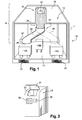
- the container 10 comprises a platform 12 provided with a lower surface 13, supporting several bins 14, here three three-wheeled bins 14A, 14B, 14C, having a large volume of waste reception.
- the platform also comprises an upper wall 16, delimiting the upper wall of the container 10 and located at track height, on which is arranged a filling device 18.
- the upper wall 16 is removable and the platform 12 is movable, the lower surface 13 thereof being able to be raised to the track height by means of a lifting device 20, which makes it possible to empty the containers 14 of the container only with the aid of a truck adapted to the emptying of conventional bins.
- the filling device 18 comprises a filling terminal 19 comprising a waste introduction orifice 22.
- the filling device 18 also comprises a duct 24, formed partially in the filling terminal and of which one distinguishes the lower part on the figure 1 .
- This duct 24 comprises a first mouth constituted by the filling orifice 22 and a second mouth 26 opening inside the container 10 and being arranged facing a container 14A of the container 10, to allow the spill in this tray 14A waste introduced into the orifice 22.
- the duct 24 comprises a first fixed portion 28, including the first mouth 22, to which is connected a bent portion, rotatable relative to the fixed portion and including the second mouthpiece 26.
- the movable portion 30 of the duct 24 is arranged to can take a first position 30, corresponding to a first configuration of the filling device, wherein it provides access to a first tray 14A and a second position 30 ', corresponding to a second configuration of the device, in which it provides access to a second bin 14C.
- the filling device 18 also comprises automatic drive means (not shown in the figure) comprising for example a motor for actuating a shaft or electric, pneumatic or hydraulic jacks connected to the movable part 30 of the duct 24.
- automatic drive means comprising for example a motor for actuating a shaft or electric, pneumatic or hydraulic jacks connected to the movable part 30 of the duct 24.
- the automatic means comprise means 32 for detecting the filling rate of a tank. These means comprise for example an ultrasonic transmitter and receiver connected to an electronic card and are electrically connected to the drive means, which they are able to control. In this way, they activate the configuration change of the mobile part 30 of the duct 24.
- the detection means activate the drive means , which move the movable portion 30 of the conduit 24 between a first position, above the first tray and a second position in which the movable portion 30 'is shown in dotted lines, located above a second tray 14C.
- the detection means 32 may also be used to slave the drive means to the precise position of a container to be associated with the filling device.
- the three tanks 14A, 14B, 14C can indeed be placed approximately in the container 10 and the centering of the mobile part 30 of the pipe 24 above a tank can be provided by detection using the means 32.
- the filling terminal 19 comprises means for closing off the insertion orifice 22, comprising a pivoting flap 34 fixed for example in the closed position to the snap-in filling device, and means for locking the flap 34 closing position (not shown on the figures).
- sealing means may also comprise electrically controlled cylinders for positioning the shutter.
- the filling device 18 also comprises a digital control pad 36 located outside the filling terminal 19 so as to be accessible to the user. This block 36 allows in particular to indicate the nature of the waste to be introduced into the container.
- the device 18 also comprises means for identifying the user, comprising a magnetic card reader 38.
- the means 36 for indicating the nature of the waste to be introduced are useful when different tanks 14A, 14B, 14C store waste of different natures (glass, paper, metal, for example). These means 36 are electrically connected to the drive means and constitute automatic means for controlling these drive means which then position the movable portion 30 of the conduit 24 above the bin storing the waste of the nature indicated by the user.
- the closure means in particular the locking means, can also be controlled by the means 32 or 36, which makes it possible to close the orifice 22 when the mobile part of the duct is being moved, in particular so as to reinforce Security. In the same way, it allows to close the orifice until the user has specified the type of waste he wanted to introduce, to facilitate sorting.
- the shutter means may also be controlled by the identification means 38, so that the flap 34 remains locked in the closed position until the user has not identified, to avoid fraud.
- the container according to the invention is aesthetic, economical but also reliable and practical operation.
- the invention is not limited to the embodiment previously described.
- the sealing means 34, indication 36 or identification 38 are for example optional.
- the container may comprise any number of trays and may be, instead of being buried as in the above embodiment, semi-buried or take place in a room.
- a waste collection device 40 is delimited by a concrete casing 41 located under the public road 43, in which is placed a structure comprising a lower platform 42 supporting four rolling bins, including two rolling bins 44A, 44B are visible on the figure 3 .
- the bins are arranged to be fixed when the device is in the buried position.
- the collection device 40 comprises a motorized device 50 elevation of the structure, so that the platform 42 can be raised up to track height so as to empty the bins more easily.
- the structure also includes lateral uprights connecting the lower platform 42 to a frame 46.
- the frame 46 supports an upper platform 48 arranged to be at track height when the device is in the buried position.
- the frame 46 also supports a plurality of ducts, of which two ducts 52A, 52B are visible on the figure 3 each duct being in front of a location of the lower platform 42 for accommodating a wheeled bin.
- Each duct comprises a first mouth opening at the frame 46, under the platform 48, and a second mouth opening into the collection device, facing one of the bins of the collection device.
- the upper platform 48 has a disk shape and is arranged on the frame 46 so as to be rotatable relative thereto around a vertical axis of rotation X passing through the center 51 of the platform 48. It is rotated by motorized means not shown on the Figures 3 and 4 . It further comprises a waste introduction terminal 50 disposed between the center 51 of the disc and the periphery thereof. The introduction terminal is rotatable with the platform.
- the insertion terminal 50 comprises a waste introduction orifice 53 intended to be closed by a hatch 54, this hatch being able to be locked, and a duct 56 having a first mouth forming the introduction orifice 53 and a second mouth opening to the platform 48.
- the introduction terminal is disposed on the platform, so that the second mouth of the conduit 56 of the introduction terminal may be located opposite the first mouth of each conduit 52A and 52B.
- the ducts 52A and 52B are of course for this reason located equidistant from the center of the upper platform 48. It is shown on the figure 4 in solid lines a first configuration that can take the introduction terminal, the other configurations being represented in dashed lines.
- the latter and / or each duct 52A, 52B may comprise a sensor, for example an ultrasonic transmitter / receiver assembly, making it possible to better adjust the angular position of the platform for that it is in front of one of the conduits 52A, 52B.
- the movement of the platform 48 can be controlled, as described in the first embodiment, by means of indicating by the user of the type of waste to be introduced, and / or by means of determining the rate filling a tray.
- the opening of the shutter door 54 can also be controlled by such means or by means of identification of the user.
- a user when a user wishes to introduce waste into the collection device, he identifies himself by means such as those described in the first embodiment, so as to open the hatch 54, allowing access to the introduction port 53 of the introduction terminal 50. It can then select the type of waste to be introduced into the collection device, using for example a numeric keypad, as described in the first embodiment.
- Each of the four collection bins is intended to store a particular type of waste. Thus, if the type of waste selected is not intended to be stored in a bin located opposite the waste introduction port, the selected type of waste triggers the rotational drive of the platform 48 around of the X axis, until the introduction terminal 50 is placed in front of the conduit 52A, 52B corresponding to the tray 44A, 44B in which the waste must be placed.
- the speed of movement of the platform is small, so that a pedestrian who ascends or descends on the platform when it is moving can not be injured.
- access to the platform can be made more difficult if it is surrounded by a barrier or a wall avoiding a passer-by lacking attention to arrive on the platform without s' to see it.
- the frame 46 'does not include a duct but the platform 48' comprises a duct 56 'having a first mouth confused with the insertion opening 52 and a second mouth opening into the collection device, way to be located in front of one of the bins set up in the collection device.
- the frame 46 'then comprises an annular slot to ensure the mobility of the conduit 56'.
- Two possible configurations of the insertion terminal 50 'and the duct 56' are respectively represented in solid lines and in dotted lines on the figure 5 .
- the elements identical to those of Figures 3 and 4 are indicated by identical references.
- the filling device is then movable in its entirety, that is to say that the conduit but also the introduction orifice and the external part of the filling device are movable.
- the device is movable only in its outer part: the filling device then comprises a plurality of fixed conduits arranged to provide access to the respective bins, the outer part of the device comprising a shell with an insertion orifice, the shell being movable so that the orifice can take different configurations, to be opposite each conduit.
- the duct is optional: the insertion orifice placed in a particular configuration can be directly placed above a tray. This embodiment is implemented in particular in the case of semi-buried containers.
- the waste introduction terminal is centered on the platform and is integral with a bent conduit, comprising a first substantially vertical portion, having a first mouth corresponding to the insertion orifice of the waste. It also comprises a second part, separated from the first part by the bend and forming a non-zero angle relative to the vertical direction. This second part comprises a second mouth capable of being located next to a collection bin.
- the conduit passes through the frame supporting the platform. As the duct is bent, the second mouth of the duct is not located right of the center of the platform, through which also the center of rotation thereof and is rotatable when the platform rotates. .
- the first part of the duct passes through the frame, because, in this case, where it crosses the platform, the duct is not very mobile, because it is substantially at the center of the platform .
- the constraints related to the crossing of the duct of the frame are therefore less and the design of the frame is freer.
- a filling device such as that shown in FIG. figure 6 , comprising a plurality of introduction orifices 60A, 60B extended respectively by ducts 61A, 61B.
- These ducts each comprise a first mouth coinciding with one of the insertion orifices and a second mouth opening into the collection device, in front of a respective waste collection tank 62A, 62B.
- the collection device also comprises closure means 64A, 64B of the insertion orifices, the closure means being controlled (for example, by the means for detecting and / or indicating the nature of the waste) to take different configurations in which the user is allowed to introduce the waste through a single orifice, the others being closed.
- two configurations of the filling device are represented: a configuration in solid lines in which a first opening 60A for introducing the waste is opened, a second opening 60B for introducing the waste being closed off by the corresponding hatch 64B, and another configuration shown in dashed lines in which the second opening 60B waste introduction is open, the first port 60A introduction being closed by the corresponding hatch 64A.
Landscapes
- Engineering & Computer Science (AREA)
- Mechanical Engineering (AREA)
- Refuse Collection And Transfer (AREA)
- Refuse Receptacles (AREA)
- Processing Of Solid Wastes (AREA)
Applications Claiming Priority (1)
| Application Number | Priority Date | Filing Date | Title |
|---|---|---|---|
| FR0752888A FR2911856B1 (fr) | 2007-01-25 | 2007-01-25 | Dispositif de remplissage d'au moins deux bacs de collecte de dechets. |
Publications (3)
| Publication Number | Publication Date |
|---|---|
| EP1953095A2 true EP1953095A2 (de) | 2008-08-06 |
| EP1953095A3 EP1953095A3 (de) | 2010-09-01 |
| EP1953095B1 EP1953095B1 (de) | 2017-10-25 |
Family
ID=38330518
Family Applications (1)
| Application Number | Title | Priority Date | Filing Date |
|---|---|---|---|
| EP08100920.1A Not-in-force EP1953095B1 (de) | 2007-01-25 | 2008-01-25 | Füllvorrichtung für mindestens zwei Abfallsammelbehälter |
Country Status (2)
| Country | Link |
|---|---|
| EP (1) | EP1953095B1 (de) |
| FR (1) | FR2911856B1 (de) |
Cited By (6)
| Publication number | Priority date | Publication date | Assignee | Title |
|---|---|---|---|---|
| EP2679520A1 (de) * | 2012-06-28 | 2014-01-01 | Paul Wolff GmbH | Einwurfgehäuse eines unterirdisch angeordneten Abfallsammelbehälters |
| EP2706022A1 (de) | 2012-09-06 | 2014-03-12 | Compagnie Plastic Omnium | Abfallbehälter |
| CN106185115A (zh) * | 2016-07-19 | 2016-12-07 | 西华大学 | 一种垃圾分类回收系统 |
| CN108661335A (zh) * | 2017-03-29 | 2018-10-16 | 五冶集团上海有限公司 | 一种用于清理高层楼板砼浇筑泵管余浆的收集装置 |
| CN110479634A (zh) * | 2019-07-18 | 2019-11-22 | 宝鸡文理学院 | 一种基于单片机多传感器的智能垃圾分类装置 |
| CN111112088A (zh) * | 2019-10-11 | 2020-05-08 | 深圳市楚凤科技有限公司 | 一种垃圾分类处理方法及装置 |
Families Citing this family (8)
| Publication number | Priority date | Publication date | Assignee | Title |
|---|---|---|---|---|
| CN108545357A (zh) * | 2018-04-13 | 2018-09-18 | 蔡宜和 | 垃圾的无害化环保回收装置 |
| CN108529067A (zh) * | 2018-04-13 | 2018-09-14 | 蔡宜和 | 一种离散式分区容纳的垃圾环保回收装置 |
| CN108502413A (zh) * | 2018-04-13 | 2018-09-07 | 蔡宜和 | 应用于市政环保的集中式垃圾回收装置 |
| CN108482911A (zh) * | 2018-04-13 | 2018-09-04 | 蔡宜和 | 垃圾的环保节能式处理方法 |
| KR101974641B1 (ko) * | 2018-05-14 | 2019-08-23 | 하천용 | 자율주행 로봇을 이용한 중앙집중형 거점식 자동 쓰레기 이송 집하 시스템 |
| CN110745420A (zh) * | 2019-11-15 | 2020-02-04 | 广州普慧环保科技股份有限公司 | 一种垃圾收集装置及系统 |
| CN111301887B (zh) * | 2020-03-13 | 2021-05-07 | 湖南工程学院 | 一种垃圾分选机器人 |
| CN112780051B (zh) * | 2021-01-06 | 2022-09-02 | 致逸(北京)建筑设计有限公司 | 一种适用于楼宇的物品输送系统 |
Family Cites Families (3)
| Publication number | Priority date | Publication date | Assignee | Title |
|---|---|---|---|---|
| FR2691492B1 (fr) * | 1992-05-22 | 1998-12-31 | Pierre Hubert | Dispositif et procede de tri selectif des dechets menagers dans l'habitat vertical. |
| FR2699837A1 (fr) * | 1992-12-24 | 1994-07-01 | Bedri Rachid | Procédé de tri des ordures ménagères par sélection directe à la source. |
| ITMN20030024A1 (it) * | 2003-06-06 | 2004-12-07 | Carlo Galeazzi | Dispositivo per la raccolta di rifiuti. |
-
2007
- 2007-01-25 FR FR0752888A patent/FR2911856B1/fr not_active Expired - Fee Related
-
2008
- 2008-01-25 EP EP08100920.1A patent/EP1953095B1/de not_active Not-in-force
Non-Patent Citations (1)
| Title |
|---|
| None |
Cited By (7)
| Publication number | Priority date | Publication date | Assignee | Title |
|---|---|---|---|---|
| EP2679520A1 (de) * | 2012-06-28 | 2014-01-01 | Paul Wolff GmbH | Einwurfgehäuse eines unterirdisch angeordneten Abfallsammelbehälters |
| EP2706022A1 (de) | 2012-09-06 | 2014-03-12 | Compagnie Plastic Omnium | Abfallbehälter |
| CN106185115A (zh) * | 2016-07-19 | 2016-12-07 | 西华大学 | 一种垃圾分类回收系统 |
| CN108661335A (zh) * | 2017-03-29 | 2018-10-16 | 五冶集团上海有限公司 | 一种用于清理高层楼板砼浇筑泵管余浆的收集装置 |
| CN110479634A (zh) * | 2019-07-18 | 2019-11-22 | 宝鸡文理学院 | 一种基于单片机多传感器的智能垃圾分类装置 |
| CN110479634B (zh) * | 2019-07-18 | 2021-05-28 | 宝鸡文理学院 | 一种基于单片机多传感器的智能垃圾分类装置 |
| CN111112088A (zh) * | 2019-10-11 | 2020-05-08 | 深圳市楚凤科技有限公司 | 一种垃圾分类处理方法及装置 |
Also Published As
| Publication number | Publication date |
|---|---|
| EP1953095B1 (de) | 2017-10-25 |
| FR2911856B1 (fr) | 2009-08-21 |
| FR2911856A1 (fr) | 2008-08-01 |
| EP1953095A3 (de) | 2010-09-01 |
Similar Documents
| Publication | Publication Date | Title |
|---|---|---|
| EP1953095B1 (de) | Füllvorrichtung für mindestens zwei Abfallsammelbehälter | |
| EP0587883B1 (de) | Vorrichtung zur trennung von münzen, automatenmünzen oder dergleichen und selbsttätige bezahlapparate | |
| EP2595904B1 (de) | Maschine zum sammeln und sortieren von abfällen | |
| FR2680121A1 (fr) | Module empileur pour machine de tri postal ou similaire. | |
| EP2388210B1 (de) | Abfallsammelbehälter mit Sammelmelder | |
| EP3590870B1 (de) | Sammelsystem für bioabfälle | |
| EP2284104A1 (de) | Vorrichtung zum Abtasten des Inhalts eines Abfallbehälters | |
| BE1009279A3 (fr) | Dispositif de reception et de tri d'objets divers, notamment de recipients a mettre au rebut. | |
| EP2706022A1 (de) | Abfallbehälter | |
| EP2284105A1 (de) | Vorrichtung zur Aufnahme eines zumindest teilweise in der Erde eingelassenen Abfallsammelbehälters | |
| FR2949108A1 (fr) | Dispostif de balayage du contenu d'un recipient a dechets temporaire et conteneur d'apport volontaire | |
| LU86189A1 (fr) | Installation automatisee de briquetage de la paroi interieure d'une enceinte | |
| EP0316226B1 (de) | Auffüllungsdetektiervorrichtung für einen Münzbehälter | |
| BE1010404A3 (fr) | Conteneur de grandes dimensions pour se debarrasser d'immondices ou de matieres ayant encore de la valeur notamment dans les maisons ou habitent plusieurs familles ou des ensembles residentiels. | |
| EP2457850A1 (de) | Sicherungsvorrichtung für ein System zum Heben und Kippen von Behältern | |
| EP2159168A1 (de) | Müllschlucker zum automatischen und getrennten Sammeln von Müll | |
| EP2542483B1 (de) | Müllcontainer mit mobiler füllöffnung | |
| FR2614609A1 (fr) | Tour magasin de stockage d'objets | |
| FR2630415A1 (fr) | Conteneur a ordures | |
| EP2465794A1 (de) | Müllsammelbehälter | |
| FR2939114A1 (fr) | Station et methode de transfert pour cartouche pneumatique | |
| WO2007000511A1 (fr) | Machine de distribution de produits et/ou de services contre paiement par billets | |
| EP0812785A1 (de) | Städtlicher Abfallbehälter und Anordnung von solchen Abfallbehältern | |
| FR2952916A1 (fr) | Module de stockage de gobelets, par exemple usages, et dispositif de collecte de gobelets usages comportant un tel module. | |
| EP1279624A1 (de) | Verfahren zur permanenten Erzeugung des Gewichtes eines Müllbehälters mit Bodenentleerung |
Legal Events
| Date | Code | Title | Description |
|---|---|---|---|
| PUAI | Public reference made under article 153(3) epc to a published international application that has entered the european phase |
Free format text: ORIGINAL CODE: 0009012 |
|
| AK | Designated contracting states |
Kind code of ref document: A2 Designated state(s): AT BE BG CH CY CZ DE DK EE ES FI FR GB GR HR HU IE IS IT LI LT LU LV MC MT NL NO PL PT RO SE SI SK TR |
|
| AX | Request for extension of the european patent |
Extension state: AL BA MK RS |
|
| PUAL | Search report despatched |
Free format text: ORIGINAL CODE: 0009013 |
|
| RIC1 | Information provided on ipc code assigned before grant |
Ipc: B65F 1/14 20060101ALI20100722BHEP Ipc: B65F 1/10 20060101AFI20100722BHEP |
|
| AK | Designated contracting states |
Kind code of ref document: A3 Designated state(s): AT BE BG CH CY CZ DE DK EE ES FI FR GB GR HR HU IE IS IT LI LT LU LV MC MT NL NO PL PT RO SE SI SK TR |
|
| AX | Request for extension of the european patent |
Extension state: AL BA MK RS |
|
| 17P | Request for examination filed |
Effective date: 20110228 |
|
| AKX | Designation fees paid |
Designated state(s): AT BE BG CH CY CZ DE DK EE ES FI FR GB GR HR HU IE IS IT LI LT LU LV MC MT NL NO PL PT RO SE SI SK TR |
|
| 17Q | First examination report despatched |
Effective date: 20110408 |
|
| GRAP | Despatch of communication of intention to grant a patent |
Free format text: ORIGINAL CODE: EPIDOSNIGR1 |
|
| STAA | Information on the status of an ep patent application or granted ep patent |
Free format text: STATUS: GRANT OF PATENT IS INTENDED |
|
| INTG | Intention to grant announced |
Effective date: 20170515 |
|
| GRAS | Grant fee paid |
Free format text: ORIGINAL CODE: EPIDOSNIGR3 |
|
| GRAA | (expected) grant |
Free format text: ORIGINAL CODE: 0009210 |
|
| STAA | Information on the status of an ep patent application or granted ep patent |
Free format text: STATUS: THE PATENT HAS BEEN GRANTED |
|
| AK | Designated contracting states |
Kind code of ref document: B1 Designated state(s): AT BE BG CH CY CZ DE DK EE ES FI FR GB GR HR HU IE IS IT LI LT LU LV MC MT NL NO PL PT RO SE SI SK TR |
|
| REG | Reference to a national code |
Ref country code: GB Ref legal event code: FG4D Free format text: NOT ENGLISH |
|
| REG | Reference to a national code |
Ref country code: CH Ref legal event code: EP |
|
| REG | Reference to a national code |
Ref country code: AT Ref legal event code: REF Ref document number: 939687 Country of ref document: AT Kind code of ref document: T Effective date: 20171115 |
|
| REG | Reference to a national code |
Ref country code: IE Ref legal event code: FG4D Free format text: LANGUAGE OF EP DOCUMENT: FRENCH |
|
| REG | Reference to a national code |
Ref country code: DE Ref legal event code: R096 Ref document number: 602008052613 Country of ref document: DE |
|
| REG | Reference to a national code |
Ref country code: FR Ref legal event code: PLFP Year of fee payment: 11 |
|
| REG | Reference to a national code |
Ref country code: NL Ref legal event code: FP |
|
| REG | Reference to a national code |
Ref country code: LT Ref legal event code: MG4D |
|
| REG | Reference to a national code |
Ref country code: AT Ref legal event code: MK05 Ref document number: 939687 Country of ref document: AT Kind code of ref document: T Effective date: 20171025 |
|
| PG25 | Lapsed in a contracting state [announced via postgrant information from national office to epo] |
Ref country code: LT Free format text: LAPSE BECAUSE OF FAILURE TO SUBMIT A TRANSLATION OF THE DESCRIPTION OR TO PAY THE FEE WITHIN THE PRESCRIBED TIME-LIMIT Effective date: 20171025 Ref country code: NO Free format text: LAPSE BECAUSE OF FAILURE TO SUBMIT A TRANSLATION OF THE DESCRIPTION OR TO PAY THE FEE WITHIN THE PRESCRIBED TIME-LIMIT Effective date: 20180125 Ref country code: SE Free format text: LAPSE BECAUSE OF FAILURE TO SUBMIT A TRANSLATION OF THE DESCRIPTION OR TO PAY THE FEE WITHIN THE PRESCRIBED TIME-LIMIT Effective date: 20171025 Ref country code: FI Free format text: LAPSE BECAUSE OF FAILURE TO SUBMIT A TRANSLATION OF THE DESCRIPTION OR TO PAY THE FEE WITHIN THE PRESCRIBED TIME-LIMIT Effective date: 20171025 Ref country code: ES Free format text: LAPSE BECAUSE OF FAILURE TO SUBMIT A TRANSLATION OF THE DESCRIPTION OR TO PAY THE FEE WITHIN THE PRESCRIBED TIME-LIMIT Effective date: 20171025 |
|
| PG25 | Lapsed in a contracting state [announced via postgrant information from national office to epo] |
Ref country code: IS Free format text: LAPSE BECAUSE OF FAILURE TO SUBMIT A TRANSLATION OF THE DESCRIPTION OR TO PAY THE FEE WITHIN THE PRESCRIBED TIME-LIMIT Effective date: 20180225 Ref country code: AT Free format text: LAPSE BECAUSE OF FAILURE TO SUBMIT A TRANSLATION OF THE DESCRIPTION OR TO PAY THE FEE WITHIN THE PRESCRIBED TIME-LIMIT Effective date: 20171025 Ref country code: LV Free format text: LAPSE BECAUSE OF FAILURE TO SUBMIT A TRANSLATION OF THE DESCRIPTION OR TO PAY THE FEE WITHIN THE PRESCRIBED TIME-LIMIT Effective date: 20171025 Ref country code: BG Free format text: LAPSE BECAUSE OF FAILURE TO SUBMIT A TRANSLATION OF THE DESCRIPTION OR TO PAY THE FEE WITHIN THE PRESCRIBED TIME-LIMIT Effective date: 20180125 Ref country code: HR Free format text: LAPSE BECAUSE OF FAILURE TO SUBMIT A TRANSLATION OF THE DESCRIPTION OR TO PAY THE FEE WITHIN THE PRESCRIBED TIME-LIMIT Effective date: 20171025 Ref country code: GR Free format text: LAPSE BECAUSE OF FAILURE TO SUBMIT A TRANSLATION OF THE DESCRIPTION OR TO PAY THE FEE WITHIN THE PRESCRIBED TIME-LIMIT Effective date: 20180126 |
|
| REG | Reference to a national code |
Ref country code: DE Ref legal event code: R097 Ref document number: 602008052613 Country of ref document: DE |
|
| PG25 | Lapsed in a contracting state [announced via postgrant information from national office to epo] |
Ref country code: EE Free format text: LAPSE BECAUSE OF FAILURE TO SUBMIT A TRANSLATION OF THE DESCRIPTION OR TO PAY THE FEE WITHIN THE PRESCRIBED TIME-LIMIT Effective date: 20171025 Ref country code: CY Free format text: LAPSE BECAUSE OF FAILURE TO SUBMIT A TRANSLATION OF THE DESCRIPTION OR TO PAY THE FEE WITHIN THE PRESCRIBED TIME-LIMIT Effective date: 20171025 Ref country code: CZ Free format text: LAPSE BECAUSE OF FAILURE TO SUBMIT A TRANSLATION OF THE DESCRIPTION OR TO PAY THE FEE WITHIN THE PRESCRIBED TIME-LIMIT Effective date: 20171025 Ref country code: SK Free format text: LAPSE BECAUSE OF FAILURE TO SUBMIT A TRANSLATION OF THE DESCRIPTION OR TO PAY THE FEE WITHIN THE PRESCRIBED TIME-LIMIT Effective date: 20171025 Ref country code: DK Free format text: LAPSE BECAUSE OF FAILURE TO SUBMIT A TRANSLATION OF THE DESCRIPTION OR TO PAY THE FEE WITHIN THE PRESCRIBED TIME-LIMIT Effective date: 20171025 |
|
| REG | Reference to a national code |
Ref country code: DE Ref legal event code: R119 Ref document number: 602008052613 Country of ref document: DE |
|
| PG25 | Lapsed in a contracting state [announced via postgrant information from national office to epo] |
Ref country code: PL Free format text: LAPSE BECAUSE OF FAILURE TO SUBMIT A TRANSLATION OF THE DESCRIPTION OR TO PAY THE FEE WITHIN THE PRESCRIBED TIME-LIMIT Effective date: 20171025 Ref country code: RO Free format text: LAPSE BECAUSE OF FAILURE TO SUBMIT A TRANSLATION OF THE DESCRIPTION OR TO PAY THE FEE WITHIN THE PRESCRIBED TIME-LIMIT Effective date: 20171025 Ref country code: IT Free format text: LAPSE BECAUSE OF FAILURE TO SUBMIT A TRANSLATION OF THE DESCRIPTION OR TO PAY THE FEE WITHIN THE PRESCRIBED TIME-LIMIT Effective date: 20171025 |
|
| PLBE | No opposition filed within time limit |
Free format text: ORIGINAL CODE: 0009261 |
|
| REG | Reference to a national code |
Ref country code: CH Ref legal event code: PL |
|
| STAA | Information on the status of an ep patent application or granted ep patent |
Free format text: STATUS: NO OPPOSITION FILED WITHIN TIME LIMIT |
|
| REG | Reference to a national code |
Ref country code: NL Ref legal event code: MM Effective date: 20180201 |
|
| GBPC | Gb: european patent ceased through non-payment of renewal fee |
Effective date: 20180125 |
|
| PG25 | Lapsed in a contracting state [announced via postgrant information from national office to epo] |
Ref country code: MT Free format text: LAPSE BECAUSE OF FAILURE TO SUBMIT A TRANSLATION OF THE DESCRIPTION OR TO PAY THE FEE WITHIN THE PRESCRIBED TIME-LIMIT Effective date: 20171025 |
|
| 26N | No opposition filed |
Effective date: 20180726 |
|
| PG25 | Lapsed in a contracting state [announced via postgrant information from national office to epo] |
Ref country code: LU Free format text: LAPSE BECAUSE OF NON-PAYMENT OF DUE FEES Effective date: 20180125 Ref country code: DE Free format text: LAPSE BECAUSE OF NON-PAYMENT OF DUE FEES Effective date: 20180801 |
|
| REG | Reference to a national code |
Ref country code: IE Ref legal event code: MM4A |
|
| REG | Reference to a national code |
Ref country code: BE Ref legal event code: MM Effective date: 20180131 |
|
| PG25 | Lapsed in a contracting state [announced via postgrant information from national office to epo] |
Ref country code: SI Free format text: LAPSE BECAUSE OF FAILURE TO SUBMIT A TRANSLATION OF THE DESCRIPTION OR TO PAY THE FEE WITHIN THE PRESCRIBED TIME-LIMIT Effective date: 20171025 Ref country code: NL Free format text: LAPSE BECAUSE OF NON-PAYMENT OF DUE FEES Effective date: 20180201 Ref country code: GB Free format text: LAPSE BECAUSE OF NON-PAYMENT OF DUE FEES Effective date: 20180125 Ref country code: CH Free format text: LAPSE BECAUSE OF NON-PAYMENT OF DUE FEES Effective date: 20180131 Ref country code: BE Free format text: LAPSE BECAUSE OF NON-PAYMENT OF DUE FEES Effective date: 20180131 Ref country code: LI Free format text: LAPSE BECAUSE OF NON-PAYMENT OF DUE FEES Effective date: 20180131 |
|
| REG | Reference to a national code |
Ref country code: NL Ref legal event code: NE Effective date: 20181218 |
|
| PG25 | Lapsed in a contracting state [announced via postgrant information from national office to epo] |
Ref country code: IE Free format text: LAPSE BECAUSE OF NON-PAYMENT OF DUE FEES Effective date: 20180125 |
|
| PGFP | Annual fee paid to national office [announced via postgrant information from national office to epo] |
Ref country code: FR Payment date: 20190128 Year of fee payment: 12 |
|
| REG | Reference to a national code |
Ref country code: NL Ref legal event code: NF Effective date: 20190430 |
|
| REG | Reference to a national code |
Ref country code: NL Ref legal event code: PD Owner name: SULO FRANCE; FR Free format text: DETAILS ASSIGNMENT: CHANGE OF OWNER(S), ASSIGNMENT; FORMER OWNER NAME: COMPAGNIE PLASTIC OMNIUM Effective date: 20190524 |
|
| PG25 | Lapsed in a contracting state [announced via postgrant information from national office to epo] |
Ref country code: MC Free format text: LAPSE BECAUSE OF FAILURE TO SUBMIT A TRANSLATION OF THE DESCRIPTION OR TO PAY THE FEE WITHIN THE PRESCRIBED TIME-LIMIT Effective date: 20171025 Ref country code: NL Free format text: LAPSE BECAUSE OF NON-PAYMENT OF DUE FEES Effective date: 20180201 |
|
| PGFP | Annual fee paid to national office [announced via postgrant information from national office to epo] |
Ref country code: NL Payment date: 20190430 Year of fee payment: 12 |
|
| PGRI | Patent reinstated in contracting state [announced from national office to epo] |
Ref country code: NL Effective date: 20190430 |
|
| PG25 | Lapsed in a contracting state [announced via postgrant information from national office to epo] |
Ref country code: TR Free format text: LAPSE BECAUSE OF FAILURE TO SUBMIT A TRANSLATION OF THE DESCRIPTION OR TO PAY THE FEE WITHIN THE PRESCRIBED TIME-LIMIT Effective date: 20171025 |
|
| PG25 | Lapsed in a contracting state [announced via postgrant information from national office to epo] |
Ref country code: HU Free format text: LAPSE BECAUSE OF FAILURE TO SUBMIT A TRANSLATION OF THE DESCRIPTION OR TO PAY THE FEE WITHIN THE PRESCRIBED TIME-LIMIT; INVALID AB INITIO Effective date: 20080125 Ref country code: PT Free format text: LAPSE BECAUSE OF FAILURE TO SUBMIT A TRANSLATION OF THE DESCRIPTION OR TO PAY THE FEE WITHIN THE PRESCRIBED TIME-LIMIT Effective date: 20171025 |
|
| REG | Reference to a national code |
Ref country code: NL Ref legal event code: MM Effective date: 20200201 |
|
| PG25 | Lapsed in a contracting state [announced via postgrant information from national office to epo] |
Ref country code: NL Free format text: LAPSE BECAUSE OF NON-PAYMENT OF DUE FEES Effective date: 20200201 Ref country code: FR Free format text: LAPSE BECAUSE OF NON-PAYMENT OF DUE FEES Effective date: 20200131 |