EP1953049A2 - Verfahren zur Montage einer elektrischen Lenksperrvorrichtung - Google Patents
Verfahren zur Montage einer elektrischen Lenksperrvorrichtung Download PDFInfo
- Publication number
- EP1953049A2 EP1953049A2 EP20070123846 EP07123846A EP1953049A2 EP 1953049 A2 EP1953049 A2 EP 1953049A2 EP 20070123846 EP20070123846 EP 20070123846 EP 07123846 A EP07123846 A EP 07123846A EP 1953049 A2 EP1953049 A2 EP 1953049A2
- Authority
- EP
- European Patent Office
- Prior art keywords
- lock
- rotation shaft
- stopper
- steering
- built
- Prior art date
- Legal status (The legal status is an assumption and is not a legal conclusion. Google has not performed a legal analysis and makes no representation as to the accuracy of the status listed.)
- Granted
Links
- 238000000034 method Methods 0.000 title claims description 24
- 238000009987 spinning Methods 0.000 claims description 4
- 238000003556 assay Methods 0.000 claims description 3
- 238000003780 insertion Methods 0.000 claims description 3
- 230000037431 insertion Effects 0.000 claims description 3
- 210000000078 claw Anatomy 0.000 description 17
- 238000009434 installation Methods 0.000 description 8
- 230000002159 abnormal effect Effects 0.000 description 2
- 239000000463 material Substances 0.000 description 2
- 125000006850 spacer group Chemical group 0.000 description 2
- 229910001220 stainless steel Inorganic materials 0.000 description 2
- 239000010935 stainless steel Substances 0.000 description 2
- FYYHWMGAXLPEAU-UHFFFAOYSA-N Magnesium Chemical compound [Mg] FYYHWMGAXLPEAU-UHFFFAOYSA-N 0.000 description 1
- 238000005299 abrasion Methods 0.000 description 1
- XAGFODPZIPBFFR-UHFFFAOYSA-N aluminium Chemical compound [Al] XAGFODPZIPBFFR-UHFFFAOYSA-N 0.000 description 1
- 229910052782 aluminium Inorganic materials 0.000 description 1
- 238000010586 diagram Methods 0.000 description 1
- -1 for instance Substances 0.000 description 1
- 230000007774 longterm Effects 0.000 description 1
- 229910052749 magnesium Inorganic materials 0.000 description 1
- 239000011777 magnesium Substances 0.000 description 1
- 238000004519 manufacturing process Methods 0.000 description 1
- 230000000717 retained effect Effects 0.000 description 1
- 238000007790 scraping Methods 0.000 description 1
- 238000004904 shortening Methods 0.000 description 1
Images


Classifications
-
- B—PERFORMING OPERATIONS; TRANSPORTING
- B60—VEHICLES IN GENERAL
- B60R—VEHICLES, VEHICLE FITTINGS, OR VEHICLE PARTS, NOT OTHERWISE PROVIDED FOR
- B60R25/00—Fittings or systems for preventing or indicating unauthorised use or theft of vehicles
- B60R25/01—Fittings or systems for preventing or indicating unauthorised use or theft of vehicles operating on vehicle systems or fittings, e.g. on doors, seats or windscreens
- B60R25/02—Fittings or systems for preventing or indicating unauthorised use or theft of vehicles operating on vehicle systems or fittings, e.g. on doors, seats or windscreens operating on the steering mechanism
- B60R25/021—Fittings or systems for preventing or indicating unauthorised use or theft of vehicles operating on vehicle systems or fittings, e.g. on doors, seats or windscreens operating on the steering mechanism restraining movement of the steering column or steering wheel hub, e.g. restraining means controlled by ignition switch
- B60R25/0215—Fittings or systems for preventing or indicating unauthorised use or theft of vehicles operating on vehicle systems or fittings, e.g. on doors, seats or windscreens operating on the steering mechanism restraining movement of the steering column or steering wheel hub, e.g. restraining means controlled by ignition switch using electric means, e.g. electric motors or solenoids
- B60R25/02153—Fittings or systems for preventing or indicating unauthorised use or theft of vehicles operating on vehicle systems or fittings, e.g. on doors, seats or windscreens operating on the steering mechanism restraining movement of the steering column or steering wheel hub, e.g. restraining means controlled by ignition switch using electric means, e.g. electric motors or solenoids comprising a locking member radially and linearly moved towards the steering column
-
- Y—GENERAL TAGGING OF NEW TECHNOLOGICAL DEVELOPMENTS; GENERAL TAGGING OF CROSS-SECTIONAL TECHNOLOGIES SPANNING OVER SEVERAL SECTIONS OF THE IPC; TECHNICAL SUBJECTS COVERED BY FORMER USPC CROSS-REFERENCE ART COLLECTIONS [XRACs] AND DIGESTS
- Y10—TECHNICAL SUBJECTS COVERED BY FORMER USPC
- Y10T—TECHNICAL SUBJECTS COVERED BY FORMER US CLASSIFICATION
- Y10T70/00—Locks
- Y10T70/50—Special application
- Y10T70/5611—For control and machine elements
- Y10T70/5646—Rotary shaft
- Y10T70/565—Locked stationary
- Y10T70/5655—Housing-carried lock
- Y10T70/5664—Latching bolt
-
- Y—GENERAL TAGGING OF NEW TECHNOLOGICAL DEVELOPMENTS; GENERAL TAGGING OF CROSS-SECTIONAL TECHNOLOGIES SPANNING OVER SEVERAL SECTIONS OF THE IPC; TECHNICAL SUBJECTS COVERED BY FORMER USPC CROSS-REFERENCE ART COLLECTIONS [XRACs] AND DIGESTS
- Y10—TECHNICAL SUBJECTS COVERED BY FORMER USPC
- Y10T—TECHNICAL SUBJECTS COVERED BY FORMER US CLASSIFICATION
- Y10T70/00—Locks
- Y10T70/70—Operating mechanism
- Y10T70/7051—Using a powered device [e.g., motor]
- Y10T70/7062—Electrical type [e.g., solenoid]
- Y10T70/7124—Retracted electrically only
-
- Y—GENERAL TAGGING OF NEW TECHNOLOGICAL DEVELOPMENTS; GENERAL TAGGING OF CROSS-SECTIONAL TECHNOLOGIES SPANNING OVER SEVERAL SECTIONS OF THE IPC; TECHNICAL SUBJECTS COVERED BY FORMER USPC CROSS-REFERENCE ART COLLECTIONS [XRACs] AND DIGESTS
- Y10—TECHNICAL SUBJECTS COVERED BY FORMER USPC
- Y10T—TECHNICAL SUBJECTS COVERED BY FORMER US CLASSIFICATION
- Y10T74/00—Machine element or mechanism
- Y10T74/18—Mechanical movements
- Y10T74/18568—Reciprocating or oscillating to or from alternating rotary
- Y10T74/18576—Reciprocating or oscillating to or from alternating rotary including screw and nut
- Y10T74/1868—Deflection related
Definitions
- the present invention relates to an assembling method of an electric steering lock device, to be applied to vehicles such as automobiles.
- JP-A-2004-231123 and JP-A-2006-36107 disclose, respectively, an electric steering lock device comprising a warm gear which rotates by a rotary motor, a helical gear which rotates by rotation of the warm gear, a lock arm and a cam which operate in association with rotation of this helical gear, a lock stopper which moves between a lock position and an unlock position with respect to a steering shaft, a lock bar, and a lock body housing these parts.
- This electric steering lock device has a configuration, in which the lock bar is moved between the lock position and the unlock position with respect to the steering shaft by mutually rotating the rotary motor in opposite directions.
- the present invention seeks to provide for a method of assembling on electric steering lock device, and said device, having advantages over known such methods and devices.
- an assembly method of an electric steering lock device comprises:
- the built-in step may comprise a step of initially building the lock bar, the first spring, and the lock stopper into the lock body from the same direction in a temporary assembled state as a sub-assay.
- the invention can provide an assembling method of an electric steering lock device, in which various components can be built into the lock body from the same direction when assembling the electric steering lock device, thereby realizing the automatic assembling.
- the screwing step may comprise a step of applying a load on the lock stopper in a direction to screw with the rotation shaft through the first spring by applying a load on the lock bar from outside, and rotating the rotation shaft, to screw the lock bar with the rotation shaft.
- the assembly method of the electric steering lock device described above may further comprise a bush insertion step of press fitting a bush to each of the holes of the lock body and a lock body lid up to a middle of each of the holes in a temporally assembled state, prior to the built-in step.
- a male screw part of the rotation shaft and a female screw part of the lock stopper are not screwed into each other as a spinning state, prior to the screwing step.
- the built-in step may be conducted in a state where no clearance is provided between an edge of the rotation shaft and a load receiving part of the bush.
- the built-in step and the screwing step may be conducted by an automatic assembling.
- the steering lock device 10 shown in Fig.1 and Fig.2 comprises a lock body 20, a rotation shaft 30, a warm wheel 31, a bush 40, a lock stopper 50, a lock bar 60, a motor 70 and a warm gear 71 etc.
- the lock body 20 comprises a main lock body 21 and a lock body lid 22.
- the main lock body 21 and the lock body lid 22 comprise a predetermined material, for instance, magnesium die-cast or aluminum die-cast.
- the main lock body 21 is installed in a predetermined position of the steering column post 1.
- a lock bar 60 projecting from a substantial central part of the main lock body 21 moves between a lock position for locking a rotation of a steering shaft 5 and an unlock position for unlocking the steering shaft 5, to switch between a connecting state and a non-connecting state with a groove part 5a of the steering shaft 5.
- Holes 2 1 a and 22a to which the bush 40 (to be described later) is fitted respectively by press fitting are formed on the main lock body 21 and the lock body lid 22. These holes 21 a and 22a are formed deeply enough so that a load receiving part 40a of the bush 40 does not reach the bottom of the holes 21a and 22a at the time of completion of assembly.
- an external screw part 30a which is screwed with a female screw part 50a formed on the lock stopper 50 (to be described later), is formed in an intermediate part, and the warm wheel 31 on which a gear is formed is installed.
- An edge 30b is supported to be slidably rotatable by each of the main lock body 21 and the lock body lid 22 at both sides through the bush 40.
- the bush 40 as shown in Figs 3A to 3E comprises a material having a spring property such as stainless steel, and is installed by fitting the main lock body 21 and the lock body lid 22 into the holes 21a and 22a with a predetermined fit.
- the bush 40 is provided with the load receiving part 40a, an installation claw part 40b, and a bearing claw part 40c.
- the load receiving part 40a functions as a contact face with the edge 30b of the rotation shaft 30, and three installation claw parts 40b and three bearing claw parts 40c are respectively provided to protrude alternately in a substantially vertical direction from this contact face side.
- the installation claw part 40b is configured to be opened from the load receiving part 40a to a top of an installation claw part 40d, so that the installation claw part 40b can be fixed to the holes 21 a and 22a formed on the main lock body 21 or the lock body lid 22 by press fitting.
- each of the top of installation claw parts 40d is inclined by only 0.2 mm outward with respect to a dimension in the load receiving part 40a.
- the installation claw part 40b is configured such that a surface press fitted to the holes 21 a and 22a functions as a burr side. This function is provided by adjusting a draft direction to a direction indicated by an arrow at the time of press work, and a sharp edge part 40e is embedded into the holes 21a and 22a, and retained therein.
- the bearing claw part 40c is configured to be narrowed from the load receiving part 40a to a top of a bearing claw part 40f, in order to support the rotation shaft 30 to be slidably rotatable.
- the bearing claw part 40c supports an outer circumference of the rotation shaft 30 by three claws.
- each of the top of bearing claw parts 40f is inclined by only 0.1mm inward with respect to a dimension of the load receiving part 40a.
- each of the top of bearing claw parts 40f is inclined by, for instance, only 0.2mm outward.
- the outer circumference of the rotation shaft 30 is supported to be slidably rotatable by the three bearing claw parts 40c without any clearance, and the edge 30b contacts to the load receiving part 40a of the bush 40 to be slidably rotatable without any clearance by the main lock body 21 and the lock body lid 22 through the bush 40 respectively.
- the rotation shaft 30 is supported to be slidably rotatable without any clearance in both radial and thrust directions.
- the lock stopper 50 is screwed with an external screw part 30a of the rotation shaft 30 at the female screw part 50a, and is movable in an axial direction of the rotation shaft 30 by the rotation of the rotation shaft 30.
- the lock stopper 50 is connected to the lock bar 60 (to be described later) through the first spring 80.
- a controller case 84 is provided with a second spring 81, so as to give a bias load to the lock stopper 50 in a direction opposite to the bias load given by the first spring 80.
- a magnet 83 is installed under the lock stopper 50 to detect the position of the lock stopper 50 by a hole IC 82.
- the lock bar 60 is connected with the lock stopper 50 through the first spring 80 and is movable between the lock position and the unlock position, so as to switch the connecting or non-connecting state with the groove part 5a of the steering shaft 5 by the rotation of the rotation shaft 30.
- the motor 70 as a driving actuator is installed in the main lock body 21 through the controller case 84 and a spacer 85.
- the warm gear 71 is installed around an axis of the motor 70.
- the warm gear 71 is screwed with a warm wheel 31 installed around the rotation shaft 30. As a result, the rotation of the motor 70 is transmitted to the rotation shaft 30 through the warm gear 71 and the warm wheel 31.
- the bush 40, the lock bar 60, the first spring 80, the lock stopper 50, the rotation shaft 30, the controller case 84, the second spring 81, the motor 70, the spacer 85, the bush 40, and the lock body lid 22 are built into the main lock body 21 from the same direction (from a right side in FIG.1 ).
- the warm wheel 31 is previously installed around the rotation shaft 30. Furthermore, it is preferable to provide a bush insertion process, in which the bush 40 is press fitted into the main lock body 21 and the holes 21 a, 22a of the lock body lid 22 until halfway through the installation of claw part 40b, as a temporary assembled state. Furthermore, it is preferable to initially prepare a temporary assembly of the lock bar 60, the first spring 80 and the lock stopper 50, as a sub-assay.
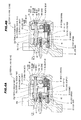
- FIG.4A shows a state in which each components are built in from the same direction and the lock body lid 22 is not connected or fixed to the main lock body 21, and
- FIG.4B shows a state in which the main lock body 21 and the lock body lid 22 are pushed from both sides to have a predetermined positional relationship and are assembled by fixing with springs etc. in the state in which each components are built in as shown in FIG.4A .
- the edge 30b of the rotation shaft 30 is press fitted to the holes 21 a, 22a while pushing the load receiving part 40a, and is assembled without any clearance (thrust) between the edge 30b of the rotation shaft 30 and the load receiving part 40a of the bush 40 (the rotation shaft built-in step). Even after this rotation shaft built-in step, the load receiving part 40a of the bush 40 does not reach to the bottom of the holes 21 a and 22a.
- the external screw part 30a of the rotation shaft 30 and the female screw part 50a of the lock stopper 50 are not initially screwed with each other, i.e. in a spinning state.
- a load is applied to the lock stopper 50 in a direction to screw with the rotation shaft 30 through the first spring 80.
- the assembly of the electric steering lock device 10 is completed, and it is possible to install the electric steering lock device 10 to the steering column post 1 in this state.
- an example of the assembled device can function such that in the state that the lock bar 60 is connected with the groove part 5a of the steering shaft 5 ( FIG.2 ), when operating a switch of the vehicle to a position such as "ACC", "ON” and "START", the motor 70 rotates in a predetermined rotational direction, the lock bar 60 is activated through the warm wheel 31, the rotation shaft 30 and the lock stopper 50, and the connection of the lock bar 60 and the steering shaft 5 are unlocked, to provide the non-connecting state.
- the motor 70 rotates at high speed (for instance, 9600 rpm).
- the rotation shaft 30 receives a strong force between the edge 30b and the load receiving part 40a of the bush 40 as a reaction.
- the edge 30b and the load receiving part 40a contact with each other in a state of being slidably rotatable without clearance and without backlash, abnormal noise such as impact sound etc. is not generated in the operation as mentioned above. Furthermore, it is similar in the radial direction. Furthermore, since the bush 40 comprises, for instance, the stainless steel, problems of scraping or abrasion by the rotation of the rotation shaft 30 do not occur in a long-term use.
- the motor 70 rotates in a rotational direction opposite to the rotational direction in the operation as mentioned above.
- the lock bar 60 is activated through the warm wheel 31, the rotation shaft 30, the lock stopper 50 and the first spring 80, and the lock bar 60 and the groove part 5a of the steering shaft 5 are unlocked, to provide the connecting state.
- the rotation shaft 30 receives a strong force between the edge 30b and the load receiving part 40a of the bush 40 as a reaction.
- the edge 30b and the load receiving part 40a contact with each other in the state of being slidably rotatable without clearance and without backlash, the abnormal noise such as the impact sound etc. is not generated in the operation as mentioned above.
- the connecting state is realized by connecting the lock bar 60 and the groove part 5a of the steering shaft 5 with the bias load of the first spring 80 at the stage that the position of the groove part 5a coincides with the position of the position of the lock bar 60 by the rotation of the steering shaft 5.
- the moving direction of the lock bar 60, the axial direction of the rotation shaft 30, the moving direction by screwing with the external screw part 30a of the rotation shaft 30 and the female screw part 50a of the lock stopper 50, the bias direction of the first spring 80 and the second spring 81, and the press fitting direction of the bush 40 to the holes 21 a, 22a are determined to be the same direction, these components can be built into the lock body 20 (the main lock body 21 and the lock body lid 22) from the same direction. As a result, the automatic assembling of the electric steering lock device 10 can be facilitated.
Landscapes
- Engineering & Computer Science (AREA)
- Mechanical Engineering (AREA)
- Lock And Its Accessories (AREA)
Applications Claiming Priority (1)
| Application Number | Priority Date | Filing Date | Title |
|---|---|---|---|
| JP2007019749A JP4991329B2 (ja) | 2007-01-30 | 2007-01-30 | 電動ステアリングロック装置の組立方法 |
Publications (3)
| Publication Number | Publication Date |
|---|---|
| EP1953049A2 true EP1953049A2 (de) | 2008-08-06 |
| EP1953049A3 EP1953049A3 (de) | 2011-04-06 |
| EP1953049B1 EP1953049B1 (de) | 2012-08-29 |
Family
ID=39402787
Family Applications (1)
| Application Number | Title | Priority Date | Filing Date |
|---|---|---|---|
| EP20070123846 Expired - Fee Related EP1953049B1 (de) | 2007-01-30 | 2007-12-20 | Verfahren zur Montage einer elektrischen Lenksperrvorrichtung |
Country Status (7)
| Country | Link |
|---|---|
| US (1) | US7823426B2 (de) |
| EP (1) | EP1953049B1 (de) |
| JP (1) | JP4991329B2 (de) |
| CN (1) | CN101234628B (de) |
| AU (1) | AU2008200283B2 (de) |
| CA (1) | CA2617687A1 (de) |
| TW (1) | TW200909265A (de) |
Cited By (2)
| Publication number | Priority date | Publication date | Assignee | Title |
|---|---|---|---|---|
| WO2011094320A1 (en) * | 2010-01-27 | 2011-08-04 | Strattec Security Corporation | Steering lock |
| FR2957317A1 (fr) * | 2010-03-09 | 2011-09-16 | Peugeot Citroen Automobiles Sa | Unite d'autodetection de chute d'un antivol de direction |
Families Citing this family (27)
| Publication number | Priority date | Publication date | Assignee | Title |
|---|---|---|---|---|
| WO2007142405A1 (en) * | 2006-06-07 | 2007-12-13 | Eung Lyul Kim | Steering lock device for coupling electronic identification system and method of manufacturing thereof |
| JP4838073B2 (ja) * | 2006-08-25 | 2011-12-14 | 株式会社東海理化電機製作所 | 磁気式位置検出装置の磁石保持構造及びステアリングロック装置 |
| US7762110B2 (en) * | 2006-10-06 | 2010-07-27 | U-Shin, Ltd. | Steering lock unit |
| JP5147217B2 (ja) * | 2006-11-10 | 2013-02-20 | 株式会社アルファ | ステアリングロック装置 |
| JP4980853B2 (ja) * | 2006-11-10 | 2012-07-18 | 株式会社アルファ | 電動ステアリングロック装置 |
| KR100820859B1 (ko) * | 2007-07-31 | 2008-04-11 | 양재우 | 차량 보안을 위한 전자 키 구조 |
| US8272239B2 (en) * | 2008-02-14 | 2012-09-25 | Fong Jian-Jhong | Anti-theft locking device for a vehicle steering wheel |
| JP5465851B2 (ja) * | 2008-08-05 | 2014-04-09 | 株式会社アルファ | ステアリングロック装置 |
| JP5385724B2 (ja) * | 2008-08-29 | 2014-01-08 | 株式会社アルファ | ステアリングロック装置 |
| FR2937602B1 (fr) * | 2008-10-23 | 2011-07-15 | Valeo Securite Habitacle | Dispositif antivol de direction pour vehicule automobile |
| WO2010122841A1 (ja) * | 2009-04-22 | 2010-10-28 | コニカミノルタオプト株式会社 | レンズ鏡胴、撮像装置及びレンズ鏡胴の製造方法 |
| JP4952751B2 (ja) * | 2009-07-24 | 2012-06-13 | アイシン精機株式会社 | 車両用ドアロック装置 |
| FR2952332B1 (fr) * | 2009-11-06 | 2013-11-29 | Valeo Securite Habitacle | Dispositif antivol pour colonne de direction de vehicule a super condamnation assuree par bascule intermediaire |
| JP5360017B2 (ja) * | 2010-08-20 | 2013-12-04 | 日本精工株式会社 | ステアリング装置 |
| JP5429110B2 (ja) * | 2010-08-20 | 2014-02-26 | 日本精工株式会社 | ステアリング装置 |
| EP2653356B1 (de) * | 2010-12-17 | 2015-05-13 | Kabushiki Kaisha Honda Lock | Elektrische fahrzeugverriegelungsvorrichtung |
| ES2457241T3 (es) * | 2011-01-21 | 2014-04-25 | Valeo Sicherheitssysteme Gmbh | Antirrobo de dirección para vehículo automóvil |
| JP5352654B2 (ja) * | 2011-03-30 | 2013-11-27 | アイシン精機株式会社 | 車両用ドアロック装置 |
| JP5809831B2 (ja) * | 2011-04-04 | 2015-11-11 | 株式会社アルファ | ステアリングロック装置 |
| JP5935115B2 (ja) * | 2011-11-28 | 2016-06-15 | 株式会社ユーシン | 電動ステアリングロック装置 |
| GB201121983D0 (en) * | 2011-12-21 | 2012-02-01 | Trw Ltd | Steering Column Assembly |
| DE102013217735A1 (de) | 2012-09-07 | 2014-03-13 | Strattec Security Corporation | Lenkschloss |
| EP2998171B1 (de) | 2013-04-18 | 2017-10-18 | NSK Ltd. | Lenksäulenverriegelung |
| CN105593078B (zh) * | 2013-10-03 | 2017-09-22 | 株式会社阿尔发 | 转向锁定装置 |
| US9731681B2 (en) | 2014-04-29 | 2017-08-15 | Strattec Security Corporation | Steering lock |
| JP5817897B2 (ja) * | 2014-08-15 | 2015-11-18 | 日本精工株式会社 | ステアリングロック装置 |
| ES2566776B1 (es) * | 2014-09-15 | 2017-01-24 | Ojmar, S.A. | Cerradura electrónica |
Citations (2)
| Publication number | Priority date | Publication date | Assignee | Title |
|---|---|---|---|---|
| JP2004231123A (ja) | 2003-01-31 | 2004-08-19 | Tokai Rika Co Ltd | 電動ステアリングロック装置 |
| JP2006036107A (ja) | 2004-07-29 | 2006-02-09 | Tokai Rika Co Ltd | ステアリングロック装置 |
Family Cites Families (14)
| Publication number | Priority date | Publication date | Assignee | Title |
|---|---|---|---|---|
| US2468333A (en) * | 1947-04-26 | 1949-04-26 | Palnut Company | Organization having adjustable screw-threaded member |
| US3767240A (en) * | 1971-07-12 | 1973-10-23 | Sogever Ltd | Electrically operated safety lock for doors |
| US4274294A (en) * | 1979-07-02 | 1981-06-23 | Rca Corporation | Apparatus for converting rotary motion to linear motion |
| JP2793300B2 (ja) * | 1989-11-30 | 1998-09-03 | 株式会社アルファ | ステアリングロック装置 |
| DE4307529C2 (de) * | 1993-03-10 | 1997-01-23 | Kodak Ag | Vorrichtung zum Ausgleichen von Steigungsfehlern bei Schraubengetrieben |
| JP2000088070A (ja) * | 1998-09-09 | 2000-03-28 | Smc Corp | 電動アクチュエータ |
| JP4491702B2 (ja) * | 2000-12-04 | 2010-06-30 | Smc株式会社 | リニアアクチュエータ |
| DE60126059T2 (de) * | 2001-04-25 | 2007-07-12 | Tornos S.A. | Antriebsschraubenmodul mit Stossdämpfung |
| DE10121714C1 (de) * | 2001-05-04 | 2003-01-02 | Huf Huelsbeck & Fuerst Gmbh | Schloß, insbesondere zum Verriegeln der Lenkspindel eines Kraftfahrzeugs |
| JP3811416B2 (ja) * | 2002-03-22 | 2006-08-23 | 株式会社東海理化電機製作所 | 電動ステアリングロック装置 |
| EP1632411A4 (de) * | 2003-04-22 | 2006-12-20 | Nsk Ltd | Lenkschlossvorrichtung |
| JP4456430B2 (ja) * | 2004-07-29 | 2010-04-28 | 株式会社東海理化電機製作所 | ステアリングロック装置 |
| JP4838073B2 (ja) * | 2006-08-25 | 2011-12-14 | 株式会社東海理化電機製作所 | 磁気式位置検出装置の磁石保持構造及びステアリングロック装置 |
| JP4932511B2 (ja) * | 2007-01-30 | 2012-05-16 | 株式会社東海理化電機製作所 | 電動ステアリングロック装置の組立方法 |
-
2007
- 2007-01-30 JP JP2007019749A patent/JP4991329B2/ja active Active
- 2007-12-04 TW TW96146091A patent/TW200909265A/zh unknown
- 2007-12-20 EP EP20070123846 patent/EP1953049B1/de not_active Expired - Fee Related
-
2008
- 2008-01-10 CA CA 2617687 patent/CA2617687A1/en not_active Abandoned
- 2008-01-21 AU AU2008200283A patent/AU2008200283B2/en not_active Ceased
- 2008-01-28 CN CN2008100069868A patent/CN101234628B/zh not_active Expired - Fee Related
- 2008-01-30 US US12/022,564 patent/US7823426B2/en active Active
Patent Citations (2)
| Publication number | Priority date | Publication date | Assignee | Title |
|---|---|---|---|---|
| JP2004231123A (ja) | 2003-01-31 | 2004-08-19 | Tokai Rika Co Ltd | 電動ステアリングロック装置 |
| JP2006036107A (ja) | 2004-07-29 | 2006-02-09 | Tokai Rika Co Ltd | ステアリングロック装置 |
Cited By (3)
| Publication number | Priority date | Publication date | Assignee | Title |
|---|---|---|---|---|
| WO2011094320A1 (en) * | 2010-01-27 | 2011-08-04 | Strattec Security Corporation | Steering lock |
| US8424348B2 (en) | 2010-01-27 | 2013-04-23 | Strattec Security Corporation | Steering lock |
| FR2957317A1 (fr) * | 2010-03-09 | 2011-09-16 | Peugeot Citroen Automobiles Sa | Unite d'autodetection de chute d'un antivol de direction |
Also Published As
| Publication number | Publication date |
|---|---|
| CA2617687A1 (en) | 2008-07-30 |
| CN101234628B (zh) | 2010-12-08 |
| EP1953049A3 (de) | 2011-04-06 |
| CN101234628A (zh) | 2008-08-06 |
| TW200909265A (en) | 2009-03-01 |
| AU2008200283B2 (en) | 2012-03-01 |
| US7823426B2 (en) | 2010-11-02 |
| EP1953049B1 (de) | 2012-08-29 |
| US20080178643A1 (en) | 2008-07-31 |
| JP2008184055A (ja) | 2008-08-14 |
| JP4991329B2 (ja) | 2012-08-01 |
| AU2008200283A1 (en) | 2008-08-14 |
Similar Documents
| Publication | Publication Date | Title |
|---|---|---|
| EP1953049B1 (de) | Verfahren zur Montage einer elektrischen Lenksperrvorrichtung | |
| EP1953050B1 (de) | Elektrische Lenksperre | |
| US11614166B2 (en) | Electromechanical park lock | |
| JP4698019B2 (ja) | ロック装置 | |
| KR100817481B1 (ko) | 자동차 스티어링 샤프트용 잠금 장치 | |
| KR100566646B1 (ko) | 자동차에서 전자 로킹 시스템 및/또는 도어, 플랩등과같이 형성된 로킹 부재를 작동시키기 위한 장치 | |
| JP5073414B2 (ja) | ステアリングロック装置 | |
| EP1978192B1 (de) | Türverriegelungsansteuervorrichtung für fahrzeug | |
| CN1325311C (zh) | 用于个人身份识别卡系统的转向盘柱锁 | |
| CN101456404B (zh) | 具有保险元件的紧凑式锁定装置 | |
| KR20030070068A (ko) | 자동차의 사이드 미러용 힌지 액츄에이터 | |
| KR20080080351A (ko) | 자동차 로크 장치용 자동 해제 로크 | |
| EP2427952B1 (de) | Elektromotorischer hilfsantrieb für fahrzeuge | |
| JP4584719B2 (ja) | 自動車用盗難防止装置 | |
| JP2017184482A (ja) | 電動アクチュエータ | |
| KR101277945B1 (ko) | 자동차의 랙 스트로크 가변장치 | |
| JP6519892B2 (ja) | 自動車ドア用ラッチ | |
| US20020078772A1 (en) | Actuator | |
| JP4701107B2 (ja) | 電動ステアリングロック装置 | |
| KR20070057195A (ko) | 조절 소자를 포함하는 기어 박스 구동 유닛 | |
| JP2007008231A (ja) | ステアリングロック装置 | |
| JP2010518277A (ja) | 自動車の回転ボルトとその製造方法 | |
| JP2008539342A (ja) | 変位装置、特にウインドーリフター、を変位する駆動軸を有する自動車モジュール、特にドアモジュール及び自動車部品特に自動車ドア、および自動車部品を組立てる方法 | |
| KR20070117206A (ko) | 전자인증시스템과 연동되는 스티어링 로크장치 및 그 제작방법 |
Legal Events
| Date | Code | Title | Description |
|---|---|---|---|
| PUAI | Public reference made under article 153(3) epc to a published international application that has entered the european phase |
Free format text: ORIGINAL CODE: 0009012 |
|
| AK | Designated contracting states |
Kind code of ref document: A2 Designated state(s): AT BE BG CH CY CZ DE DK EE ES FI FR GB GR HU IE IS IT LI LT LU LV MC MT NL PL PT RO SE SI SK TR |
|
| AX | Request for extension of the european patent |
Extension state: AL BA HR MK RS |
|
| PUAL | Search report despatched |
Free format text: ORIGINAL CODE: 0009013 |
|
| AK | Designated contracting states |
Kind code of ref document: A3 Designated state(s): AT BE BG CH CY CZ DE DK EE ES FI FR GB GR HU IE IS IT LI LT LU LV MC MT NL PL PT RO SE SI SK TR |
|
| AX | Request for extension of the european patent |
Extension state: AL BA HR MK RS |
|
| 17P | Request for examination filed |
Effective date: 20110621 |
|
| AKX | Designation fees paid |
Designated state(s): DE FR GB |
|
| REG | Reference to a national code |
Ref country code: DE Ref legal event code: R079 Ref document number: 602007025086 Country of ref document: DE Free format text: PREVIOUS MAIN CLASS: B60R0025020000 Ipc: B60K0035000000 |
|
| GRAP | Despatch of communication of intention to grant a patent |
Free format text: ORIGINAL CODE: EPIDOSNIGR1 |
|
| RIC1 | Information provided on ipc code assigned before grant |
Ipc: B60K 35/00 20060101AFI20120425BHEP |
|
| RIN1 | Information on inventor provided before grant (corrected) |
Inventor name: OKUNO, MASANARI C/O TOKAI RIKA CO. LTD Inventor name: HASEGAWA, HIROYASU C/O TOKAI RIKA CO. LTD Inventor name: INOUE, NOBUHISA C/O TOYOTA JIDOSHA KABUSHIKI KAISH |
|
| GRAS | Grant fee paid |
Free format text: ORIGINAL CODE: EPIDOSNIGR3 |
|
| GRAA | (expected) grant |
Free format text: ORIGINAL CODE: 0009210 |
|
| AK | Designated contracting states |
Kind code of ref document: B1 Designated state(s): DE FR GB |
|
| REG | Reference to a national code |
Ref country code: GB Ref legal event code: FG4D |
|
| REG | Reference to a national code |
Ref country code: DE Ref legal event code: R096 Ref document number: 602007025086 Country of ref document: DE Effective date: 20121025 |
|
| PGFP | Annual fee paid to national office [announced via postgrant information from national office to epo] |
Ref country code: DE Payment date: 20121213 Year of fee payment: 6 |
|
| PGFP | Annual fee paid to national office [announced via postgrant information from national office to epo] |
Ref country code: GB Payment date: 20121219 Year of fee payment: 6 |
|
| PGFP | Annual fee paid to national office [announced via postgrant information from national office to epo] |
Ref country code: FR Payment date: 20130107 Year of fee payment: 6 |
|
| PLBE | No opposition filed within time limit |
Free format text: ORIGINAL CODE: 0009261 |
|
| STAA | Information on the status of an ep patent application or granted ep patent |
Free format text: STATUS: NO OPPOSITION FILED WITHIN TIME LIMIT |
|
| 26N | No opposition filed |
Effective date: 20130530 |
|
| REG | Reference to a national code |
Ref country code: DE Ref legal event code: R097 Ref document number: 602007025086 Country of ref document: DE Effective date: 20130530 |
|
| REG | Reference to a national code |
Ref country code: DE Ref legal event code: R119 Ref document number: 602007025086 Country of ref document: DE |
|
| GBPC | Gb: european patent ceased through non-payment of renewal fee |
Effective date: 20131220 |
|
| REG | Reference to a national code |
Ref country code: DE Ref legal event code: R119 Ref document number: 602007025086 Country of ref document: DE Effective date: 20140701 |
|
| REG | Reference to a national code |
Ref country code: FR Ref legal event code: ST Effective date: 20140829 |
|
| PG25 | Lapsed in a contracting state [announced via postgrant information from national office to epo] |
Ref country code: DE Free format text: LAPSE BECAUSE OF NON-PAYMENT OF DUE FEES Effective date: 20140701 |
|
| PG25 | Lapsed in a contracting state [announced via postgrant information from national office to epo] |
Ref country code: FR Free format text: LAPSE BECAUSE OF NON-PAYMENT OF DUE FEES Effective date: 20131231 Ref country code: GB Free format text: LAPSE BECAUSE OF NON-PAYMENT OF DUE FEES Effective date: 20131220 |