EP1950693B1 - Kartenverarbeitungsgerät - Google Patents
Kartenverarbeitungsgerät Download PDFInfo
- Publication number
- EP1950693B1 EP1950693B1 EP08001008A EP08001008A EP1950693B1 EP 1950693 B1 EP1950693 B1 EP 1950693B1 EP 08001008 A EP08001008 A EP 08001008A EP 08001008 A EP08001008 A EP 08001008A EP 1950693 B1 EP1950693 B1 EP 1950693B1
- Authority
- EP
- European Patent Office
- Prior art keywords
- card
- path
- processing apparatus
- shutter
- inlet slot
- Prior art date
- Legal status (The legal status is an assumption and is not a legal conclusion. Google has not performed a legal analysis and makes no representation as to the accuracy of the status listed.)
- Not-in-force
Links
Images


Classifications
-
- G—PHYSICS
- G06—COMPUTING OR CALCULATING; COUNTING
- G06K—GRAPHICAL DATA READING; PRESENTATION OF DATA; RECORD CARRIERS; HANDLING RECORD CARRIERS
- G06K13/00—Conveying record carriers from one station to another, e.g. from stack to punching mechanism
- G06K13/02—Conveying record carriers from one station to another, e.g. from stack to punching mechanism the record carrier having longitudinal dimension comparable with transverse dimension, e.g. punched card
- G06K13/08—Feeding or discharging cards
- G06K13/0868—Feeding or discharging cards using an arrangement for keeping the feeding or insertion slot of the card station clean of dirt, or to avoid feeding of foreign or unwanted objects into the slot
- G06K13/0875—Feeding or discharging cards using an arrangement for keeping the feeding or insertion slot of the card station clean of dirt, or to avoid feeding of foreign or unwanted objects into the slot the arrangement comprising a shutter for blocking at least part of the card insertion slot
Definitions
- the present invention relates to a card processing apparatus that takes in a card such as a magnetic card, and then reads and writes information data from/to the card.
- Magnetic cards and IC cards are generally used, for example at banking facilities and automatic vending machines, as cards for implementation of personal verification and cashless service.
- a magnetic card includes magnetic stripes formed on a surface of a plastic substrate, and an IC card includes an IC chip embedded in a plastic substrate. Reading and writing information data from/to these cards is carried out by a card processing apparatus (a card reader) equipped with a magnetic head and/or an IC contact.
- the card processing apparatus is usually mounted, for example, on a higher-level device (or a panel of the higher-level device) such as an automatic vending machine.
- a tamper-resistant case for the purpose of prevention of any tampering access.
- a tamper-resistant case for the purpose of prevention of any tampering access.
- a tamper-resistant case is placed in order to cover various elements including a circuit board (an electronic circuit plate 7 in US 5698832 .
- US 6176426 B discloses a card reader comprising a foreign material removal passage that has an inlet and an outlet. From said inlet toward said outlet, said foreign material removal passage slopes away from said card passage and extends in a direction toward said card insertion slot.
- the card reader In a case where the card reader is used in an outdoor environment (for example, being mounted at an automatic vending machine), it is required to prevent the card reader devices from any failure resulted from somewhat of rainwater infiltrated through a card inlet slot.
- the card reader equipped with the case described above may not enable prevention of the problem of such failure.
- the card reader may impair convenience performance.
- a cover member (a hood, etc.) may be placed around the card inlet slot to prevent any rainwater infiltration.
- the cover member itself is additionally required so as to cause an increase of production cost.
- the cover member needs to be opened and closed so as to worsen operation performance and impair convenience performance.
- the cover member despite the cover member being used; if once rainwater has infiltrated through the card inlet slot, the rainwater gets accumulated inside the case and the accumulated rainwater may cause malfunction of the card reader devices.
- the present invention provides a card processing apparatus according to claim 1.
- the tilted part is tilted so as to become further away gradually from the card path in the direction from the inner part of the case body toward the front bezel, it is not needed to tilt an entire part of the card processing apparatus in an obliquely front-downward direction (Tilting the card processing apparatus in an obliquely front-downward direction brings difficulty for inserting the card into the card inlet slot and worsens card operation performance). Therefore, this arrangement enables prevention of deterioration of convenience performance, such as worsening card operation performance.
- the card processing apparatus includes the card processing section (such as an IC contact) located at the inner side of the card path for reading and writing information data recorded in the card. Therefore, malfunction of the card reader devices can effectively be avoided.
- the card processing section such as an IC contact
- structural elements according to the present invention include not only the tilted part and the liquid drain holes but also the shutter placed between the card inlet slot and the card path. Therefore, even though rainwater and so on get infiltrated into the case, the rainwater and so on are unlikely to reach an inner side of the card path as far as the shutter is closed. Thus, by locating the card processing section at the card path, it becomes possible more surely to prevent malfunction of the card reader devices (for example, failure due to short-circuiting of the lC contact protruded to the card path).
- the card path is so placed as to have the card inserted in the horizontal direction from the card inlet slot, and the control circuit board for controlling the card processing apparatus is located at the position higher than the card path. Therefore, even if water passes through the shutter to get infiltrated into the card path (for example, a drenched card is inserted), the water drops to the tilted part. Then, the control circuit board is unlikely to get drenched, and it becomes possible more surely to prevent malfunction of the card reader devices.
- the breaking-in protection member for example, a metallic plate working for preventing any foreign material breaking in through the liquid drain holes is placed at the card processing apparatus' inner side of the liquid drain holes. Therefore, even if a stick is recklessly poked into the liquid drain holes, this arrangement can prevent damages of internals of the card processing apparatus (for example, internals of the tilted part).
- a card processing apparatus relating to the present invention makes it possible to prevent any water being accumulated in the case and to keep devices of the card processing apparatus from failure while convenience performance of the devices being taken into consideration.
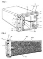
- FIG. 1 is a perspective view showing an external structural view of a card reader 1 relating to an embodiment of the present invention.
- FIG. 2 is a side view of the card reader 1 shown in FIG. 1 .
- the card reader 1 shown in FIG. 1 is applied as a card processing apparatus in the present embodiment, the present invention can also be applied to other kinds of card readers.
- the card reader 1 includes a front bezel 10 having a front face 11 and a card inlet slot 12, both of which expose themselves from an opening of a panel of a higher-level device; a card path 21 (Refer to FIG. 4 to be explained later) extending from the card inlet slot 12; and a case body 20 closely contacting the front bezel 10 and having the card path 21 internally.
- the case body 20 is assembled to the front bezel 10 with screws 17.
- a circumferential contacting surface 13 that contacts the panel of the higher-level device (not illustrated), and fixing surfaces 14 that contact protrusions located at a rear side (a side toward the higher-level device) of the panel.
- 4 fixing surfaces 14 are formed at 4 corners of the front bezel 10, and accordingly there are also 4 protrusions located at the rear side of the panel of the higher-level device.
- the front face 11, the circumferential contacting surface 13, and the fixing surfaces 14 are formed in a step structure in a direction toward an inside of the higher-level device. As a result, only the front face 11 can be seen externally through the panel.
- the case body 20 includes a top wall 20a, a side wall 20b, and a bottom wall 20c.
- the bottom wall 20c is tilted for about 10 degrees. Namely, in a direction from an inner part of the case body 20 toward the front bezel 10, the bottom wall 20c is tilted so as to become further away gradually from the card path 21.
- This arrangement leads a liquid infiltrated through the card inlet slot to the front bezel 10.
- the bottom wall 20c works as "a tilted part".
- the card reader 1 is fixed with screws to the panel of the higher-level device by using mounting holes 18.
- the card reader 1 relating to the present embodiment is equipped with liquid drain holes 30 that are located at (a lower section of) a front surface of the front bezel 10 and go through to a side of the case body 20 for draining the liquid. Since these drain holes are placed, any rainwater and so on can be drained afterward even if such a liquid once infiltrates through card inlet slot 12 into the case body 20. Described below in detail with reference to FIG. 3 through FIG. 5 is a way of draining the liquid through the liquid drain holes 30.
- FIG. 3 is a front elevation view of the card reader 1 relating to the embodiment of the present invention.
- FIG. 4 is a cross sectional view of the card reader 1 shown in FIG. 3 , taken along the line A-A in the figure.
- FIG. 5 is a cross sectional view of the card reader 1 shown in FIG. 3 , taken along the line B-B in the figure.
- the card path 21 described above continuously extends from the card inlet slot 12. Furthermore, placed at an inner side of the card path 21 so as to face the card path 21 is a card processing section 25 that reads and writes information data from/to a card.
- the card processing section 25 includes, for example, a magnetic head 60 and an IC contact 50.
- the card path 21 is so placed as to have a card inserted horizontally from the card inlet slot 12 when the card reader 1 is installed horizontally.
- a control circuit board 24 for controlling the card reader 1 is positioned over the card path 21 that is placed as described above.
- the card reader 1 is sealed with the case body 20, and there is a hollow section between a lower side of the card path 21 and the case body 20. Accordingly, there is a chance that water infiltrated into the card path 21 passes through the hollow section to drop to the bottom wall 20c of the case body 20.
- a shutter 22 placed between the card inlet slot 12 and the card path 21 is a shutter 22 that opens and closes the card path 21.
- the shutter 22 is so pressed in a direction as to close the card path 21 by a shutter returning spring.
- the shutter 22 gets opened by the card.
- the shutter 22 gets closed by the shutter returning spring at the time when the card gets out of the shutter 22.
- a full-range shutter that covers a full extent of the card path 21 is used as the shutter.
- a rib 20d is formed at an edge (a front end) of the bottom wall 20c of the case body 20, and the rib 20d prevents any water leakage at a connection part between the bottom wall 20c and the front bezel 10.
- the rib 20d is extended from the case body 20 for overlapping so that the infiltrated water is guided to the liquid drain holes 30 more surely and this arrangement also prevents any water infiltration from the connection part due to backwater.
- a sealing member 40 (a packing) made of sponge, rubber, or any equivalent is placed at a lower part of the connection part between the bottom wall 20c and the front bezel 10 to prevent any water infiltration through the connection part more surely.
- a metallic plate 23 is installed at a root side of the rib 20d in a direction perpendicular to the card insertion direction.
- the metallic plate 23 is as an example of a breaking-in protection member working for preventing any foreign material breaking in through the liquid drain holes 30.
- the metallic plate 23 made of metal is used in this embodiment as the member for preventing any foreign material, but the material of the metallic plate 23 is not limited to metal and any other material can be used.
- the bottom wall 20c of the case body 20 is tilted. Therefore, water infiltrated into the case body 20 can be drained externally through the liquid drain holes 30 (Since no drain tube is used, this arrangement enables a manufacturing process to be simplified and production costs to be reduced).
- the card reader 1 when the card reader 1 is installed into the higher-level device, it is not required to tilt an entire part of the card reader 1 (a unit) in an obliquely frontward direction. Therefore, this arrangement can prevent card operation performance from worsening, such as card insertion into the card inlet slot 12 becoming difficult.
- the card processing section 25 placed so as to face the card path 21 is unlikely to get drenched while the shutter 22 is closed.
- most of water infiltrated through the card inlet slot 12 is blocked at the shutter 22 and the blocked water drops to the bottom wall 20c of the case body 20.
- the dropped water flows along the bottom wall 20c to the front bezel 10, and eventually drains off externally through the liquid drain holes 30.
- the metallic plate 23 Since the metallic plate 23 is installed at the root side of the rib 20d, the metallic plate 23 can prevent a stick from reaching the bottom wall 20c even if the stick is poked through the liquid drain holes 30, so that this arrangement can prevent damages of internals of the card processing apparatus.
- size of the liquid drain holes 30 is set to be greater than size of all gaps which may cause water infiltration, including a gap between the front bezel 10 and a main body of the card reader 1, and so on. Therefore, water infiltrated into the case body 20 can effectively be drained externally through the liquid drain holes 30.
- the card processing apparatus relating to the present invention is useful for enabling prevention of water accumulation inside a case, even if the card processing apparatus is equipped with the case, while avoiding deterioration of convenience performance.
Landscapes
- Physics & Mathematics (AREA)
- General Physics & Mathematics (AREA)
- Engineering & Computer Science (AREA)
- Theoretical Computer Science (AREA)
- Control Of Vending Devices And Auxiliary Devices For Vending Devices (AREA)
- Conveying Record Carriers (AREA)
Claims (4)
- Kartenverarbeitungsgerät mit:einer Frontblende (10),einem Karteneinführungsschlitz (12), der in der Frontblende (10) angeordnet ist,einem Kartenpfad (21), der sich vom Karteneinführungsschlitz (12) kontinuierlich erstreckt,einem Schließelement (22), das zwischen dem Karteneinführungsschlitz (12) und dem Kartenpfad (21) zum Öffnen und Schließen des Kartenpfades (21) installiert ist,einem Gehäusekörper (20), der die Frontblende (10) berührt und den Kartenpfad (21) enthält, undeinem geneigten Teil (20c), der so geneigt ist, dass sich sein Abstand vom Kartenpfad (21) in Richtung von einem inneren Teil des Gehäusekörpers (20) zur Frontblende (10) vergrößert, um durch den Karteneinführungsschlitz (12) eingedrungene Flüssigkeit zu führen,dadurch gekennzeichnet, dass
der geneigte Teil (20c) so geneigt ist, dass er sich zur Frontseite der Frontblende (10) in Bezug auf das Verschlusselement (22) erstreckt,
eine hohle Sektion zumindest unterhalb des Verschlusselementes (22) zwischen dem Kartenpfad (21) und dem geneigten Teil (20c) vorgesehen ist,
Flüssigkeitsdrainagelöcher (30) an der Frontseite der Frontblende (10) angeordnet sind, um sich zu einer Seite des Gehäusekörpers (20) zur Ableitung der Flüssigkeit kontinuierlich zu erstrecken,
eine Steuerungsschaltkreisplatine (24) zur Steuerung des Kartenverarbeitungsgerätes an einer Stelle höher als der Kartenpfad (21) angeordnet ist, und
das Verschlusselement (22) ein Vollbereichsverschlusselement ist, das den Kartenpfad (21) über seinen gesamten Querschnitt überdeckt und vorgesehen ist, den Eintritt von Fremdstoften in den Kartenpfad (21) zu verhindern,
wobei durch den Karteneinführungsschlitz (12) eingedrungene Flüssigkeit durch das Verschlusselement (22) blockiert wird und die blockierte Flüssigkeit durch die hohle Sektion direkt auf den geneigten Teil (20c) tropft und entlang des geneigten Teils (20c) zu den Flüssigkeitsdrainagelöchern (30) an der Frontseite der Frontblende (10) fließt. - Kartenverarbeitungsgerät nach Anspruch 1, ferner mit einer Kartenverarbeitungssektion (25), die an einer Innenseite des Kartenpfades (21) zum Lesen und Schreiben von in einer Karte aufgezeichneten Informationsdaten angeordnet ist.
- Kartenverarbeitungsgerät nach Anspruch 1 oder 2,
bei welchem der Kartenpfad (21) so angeordnet ist, dass die Karte vom Karteneinführungsschlitz (12) in horizontaler Richtung eingeführt wird. - Kartenverarbeitungsgerät nach mindestens einem der Ansprüche 1 bis 3, bei welchem ein Schutzelement (23), das ein Eindringen von Fremdstoffen durch die Flüssigkeitsdrainagelöcher (30) verhindert, an der Innenseite der Flüssigkeitsdrainagelöcher (30) des Kartenverarbeitungsgerätes angeordnet ist.
Applications Claiming Priority (1)
| Application Number | Priority Date | Filing Date | Title |
|---|---|---|---|
| JP2007016924A JP5088931B2 (ja) | 2007-01-26 | 2007-01-26 | カード処理装置 |
Publications (3)
| Publication Number | Publication Date |
|---|---|
| EP1950693A2 EP1950693A2 (de) | 2008-07-30 |
| EP1950693A3 EP1950693A3 (de) | 2011-06-01 |
| EP1950693B1 true EP1950693B1 (de) | 2012-08-22 |
Family
ID=39367717
Family Applications (1)
| Application Number | Title | Priority Date | Filing Date |
|---|---|---|---|
| EP08001008A Not-in-force EP1950693B1 (de) | 2007-01-26 | 2008-01-21 | Kartenverarbeitungsgerät |
Country Status (3)
| Country | Link |
|---|---|
| US (1) | US8251293B2 (de) |
| EP (1) | EP1950693B1 (de) |
| JP (1) | JP5088931B2 (de) |
Families Citing this family (49)
| Publication number | Priority date | Publication date | Assignee | Title |
|---|---|---|---|---|
| US6676127B2 (en) | 1997-03-13 | 2004-01-13 | Shuffle Master, Inc. | Collating and sorting apparatus |
| US6655684B2 (en) | 1998-04-15 | 2003-12-02 | Shuffle Master, Inc. | Device and method for forming and delivering hands from randomly arranged decks of playing cards |
| US6254096B1 (en) | 1998-04-15 | 2001-07-03 | Shuffle Master, Inc. | Device and method for continuously shuffling cards |
| US8590896B2 (en) | 2000-04-12 | 2013-11-26 | Shuffle Master Gmbh & Co Kg | Card-handling devices and systems |
| US7677565B2 (en) | 2001-09-28 | 2010-03-16 | Shuffle Master, Inc | Card shuffler with card rank and value reading capability |
| US8616552B2 (en) | 2001-09-28 | 2013-12-31 | Shfl Entertainment, Inc. | Methods and apparatuses for an automatic card handling device and communication networks including same |
| US8011661B2 (en) | 2001-09-28 | 2011-09-06 | Shuffle Master, Inc. | Shuffler with shuffling completion indicator |
| US7753373B2 (en) | 2001-09-28 | 2010-07-13 | Shuffle Master, Inc. | Multiple mode card shuffler and card reading device |
| US8337296B2 (en) | 2001-09-28 | 2012-12-25 | SHFL entertaiment, Inc. | Method and apparatus for using upstream communication in a card shuffler |
| US6886829B2 (en) | 2002-02-08 | 2005-05-03 | Vendingdata Corporation | Image capturing card shuffler |
| US20060066048A1 (en) | 2004-09-14 | 2006-03-30 | Shuffle Master, Inc. | Magnetic jam detection in a card shuffler |
| US7764836B2 (en) | 2005-06-13 | 2010-07-27 | Shuffle Master, Inc. | Card shuffler with card rank and value reading capability using CMOS sensor |
| US7556266B2 (en) | 2006-03-24 | 2009-07-07 | Shuffle Master Gmbh & Co Kg | Card shuffler with gravity feed system for playing cards |
| US8353513B2 (en) | 2006-05-31 | 2013-01-15 | Shfl Entertainment, Inc. | Card weight for gravity feed input for playing card shuffler |
| US8342525B2 (en) | 2006-07-05 | 2013-01-01 | Shfl Entertainment, Inc. | Card shuffler with adjacent card infeed and card output compartments |
| US8579289B2 (en) | 2006-05-31 | 2013-11-12 | Shfl Entertainment, Inc. | Automatic system and methods for accurate card handling |
| US8070574B2 (en) | 2007-06-06 | 2011-12-06 | Shuffle Master, Inc. | Apparatus, system, method, and computer-readable medium for casino card handling with multiple hand recall feature |
| US8919775B2 (en) | 2006-11-10 | 2014-12-30 | Bally Gaming, Inc. | System for billing usage of an automatic card handling device |
| US8967621B2 (en) | 2009-04-07 | 2015-03-03 | Bally Gaming, Inc. | Card shuffling apparatuses and related methods |
| US7988152B2 (en) | 2009-04-07 | 2011-08-02 | Shuffle Master, Inc. | Playing card shuffler |
| JP5264676B2 (ja) * | 2009-08-07 | 2013-08-14 | 日本電産サンキョー株式会社 | カードリーダ |
| US8800993B2 (en) | 2010-10-14 | 2014-08-12 | Shuffle Master Gmbh & Co Kg | Card handling systems, devices for use in card handling systems and related methods |
| JP5736045B2 (ja) * | 2011-05-25 | 2015-06-17 | 日立オムロンターミナルソリューションズ株式会社 | カード取扱装置 |
| US8485527B2 (en) | 2011-07-29 | 2013-07-16 | Savant Shuffler LLC | Card shuffler |
| US9731190B2 (en) | 2011-07-29 | 2017-08-15 | Bally Gaming, Inc. | Method and apparatus for shuffling and handling cards |
| US8960674B2 (en) | 2012-07-27 | 2015-02-24 | Bally Gaming, Inc. | Batch card shuffling apparatuses including multi-card storage compartments, and related methods |
| US9511274B2 (en) | 2012-09-28 | 2016-12-06 | Bally Gaming Inc. | Methods for automatically generating a card deck library and master images for a deck of cards, and a related card processing apparatus |
| US9378766B2 (en) | 2012-09-28 | 2016-06-28 | Bally Gaming, Inc. | Card recognition system, card handling device, and method for tuning a card handling device |
| JP6078457B2 (ja) * | 2013-11-08 | 2017-02-08 | 日本電産サンキョー株式会社 | カードリーダ |
| EP3113855B1 (de) | 2014-04-11 | 2019-04-10 | Bally Gaming, Inc. | Methode und vorrichtung zum mischen und zur handhabung von karten |
| US9474957B2 (en) | 2014-05-15 | 2016-10-25 | Bally Gaming, Inc. | Playing card handling devices, systems, and methods for verifying sets of cards |
| USD764599S1 (en) | 2014-08-01 | 2016-08-23 | Bally Gaming, Inc. | Card shuffler device |
| US9566501B2 (en) | 2014-08-01 | 2017-02-14 | Bally Gaming, Inc. | Hand-forming card shuffling apparatuses including multi-card storage compartments, and related methods |
| US9504905B2 (en) | 2014-09-19 | 2016-11-29 | Bally Gaming, Inc. | Card shuffling device and calibration method |
| JP6357406B2 (ja) * | 2014-10-30 | 2018-07-11 | 日本電産サンキョー株式会社 | カードリーダ |
| CN105590366B (zh) * | 2014-11-14 | 2018-05-15 | 日立金融设备系统(深圳)有限公司 | 自动交易装置及自动交易装置的假卡检测方法 |
| US9993719B2 (en) | 2015-12-04 | 2018-06-12 | Shuffle Master Gmbh & Co Kg | Card handling devices and related assemblies and components |
| US10339765B2 (en) | 2016-09-26 | 2019-07-02 | Shuffle Master Gmbh & Co Kg | Devices, systems, and related methods for real-time monitoring and display of related data for casino gaming devices |
| US10933300B2 (en) | 2016-09-26 | 2021-03-02 | Shuffle Master Gmbh & Co Kg | Card handling devices and related assemblies and components |
| JP6897283B2 (ja) * | 2017-04-27 | 2021-06-30 | 株式会社デンソー | 車両用媒体読み取り装置 |
| US11376489B2 (en) | 2018-09-14 | 2022-07-05 | Sg Gaming, Inc. | Card-handling devices and related methods, assemblies, and components |
| SG11202102480VA (en) | 2018-09-14 | 2021-04-29 | Sg Gaming Inc | Card-handling devices and related methods, assemblies, and components |
| US11896891B2 (en) | 2018-09-14 | 2024-02-13 | Sg Gaming, Inc. | Card-handling devices and related methods, assemblies, and components |
| US11338194B2 (en) | 2018-09-28 | 2022-05-24 | Sg Gaming, Inc. | Automatic card shufflers and related methods of automatic jam recovery |
| PH12020050309A1 (en) | 2019-09-10 | 2021-03-22 | Shuffle Master Gmbh And Co Kg | Card-handling devices with defect detection and related methods |
| US11173383B2 (en) | 2019-10-07 | 2021-11-16 | Sg Gaming, Inc. | Card-handling devices and related methods, assemblies, and components |
| US11443123B2 (en) | 2021-01-05 | 2022-09-13 | Elo Touch Solutions, Inc. | Liquid impervious smart card reader |
| FR3144377A1 (fr) * | 2022-12-23 | 2024-06-28 | Banks And Acquirers International Holding | Terminal de paiement électronique à drainage de liquide indésirable optimisé |
| CN221040034U (zh) * | 2023-09-28 | 2024-05-28 | 东莞富强电子有限公司 | 具有防护机构的读卡机 |
Family Cites Families (10)
| Publication number | Priority date | Publication date | Assignee | Title |
|---|---|---|---|---|
| JPH0227249U (de) | 1988-08-08 | 1990-02-22 | ||
| JP2689705B2 (ja) * | 1990-08-03 | 1997-12-10 | 富士電機株式会社 | カード端末機 |
| US5698832A (en) | 1995-03-31 | 1997-12-16 | Neuron Corporation | Magnetic card reading apparatus |
| US5892210A (en) * | 1996-10-10 | 1999-04-06 | Coin Acceptors, Inc. | Smart card reader with liquid diverter system |
| JP3376893B2 (ja) * | 1997-10-28 | 2003-02-10 | 松下電器産業株式会社 | カードリーダ |
| US6042010A (en) * | 1997-01-10 | 2000-03-28 | Matsushita Electric Industrial Co., Ltd. | Card reader and a method of installing a card reader |
| JP3959297B2 (ja) * | 2002-04-10 | 2007-08-15 | 日立オムロンターミナルソリューションズ株式会社 | 紙幣取扱装置 |
| US6983879B2 (en) * | 2002-11-26 | 2006-01-10 | Diebold Self-Service Systems Division Of Diebold, Incorporated | Cash dispensing automated banking machine with improved resistance to fraud |
| US7364076B2 (en) * | 2004-10-25 | 2008-04-29 | Nidec Sankyo Corporation | Card reader |
| US7870997B2 (en) * | 2005-07-01 | 2011-01-18 | Diebold Self-Service Systems Division Of Diebold Incorporated | ATM that can center different sized cash stacks in a cash outlet opening |
-
2007
- 2007-01-26 JP JP2007016924A patent/JP5088931B2/ja not_active Expired - Fee Related
-
2008
- 2008-01-21 EP EP08001008A patent/EP1950693B1/de not_active Not-in-force
- 2008-01-28 US US12/020,617 patent/US8251293B2/en active Active
Also Published As
| Publication number | Publication date |
|---|---|
| US20080185442A1 (en) | 2008-08-07 |
| JP2008186085A (ja) | 2008-08-14 |
| EP1950693A3 (de) | 2011-06-01 |
| JP5088931B2 (ja) | 2012-12-05 |
| EP1950693A2 (de) | 2008-07-30 |
| US8251293B2 (en) | 2012-08-28 |
Similar Documents
| Publication | Publication Date | Title |
|---|---|---|
| EP1950693B1 (de) | Kartenverarbeitungsgerät | |
| US6042010A (en) | Card reader and a method of installing a card reader | |
| US8302857B2 (en) | Tamper detection mechanism and card processing device | |
| US9036366B2 (en) | Terminal unit | |
| EP0725401A2 (de) | Datenspeicheranordnung und diese verwendende Datenverarbeitungsanordnung | |
| US8081445B2 (en) | Drainage structure and information processing unit | |
| KR20060097979A (ko) | 탑 로딩식 카드 어댑터 | |
| JP2000024268A (ja) | 遊技機 | |
| JPH11226219A (ja) | 制御基板ボックス、成形金型、射出成形方法及び遊技機の制御基板 | |
| JP2689705B2 (ja) | カード端末機 | |
| CN1788273A (zh) | 卡接收装置 | |
| JP2008227289A (ja) | 電子機器 | |
| JP7267528B2 (ja) | カードリーダ収納ケース及びこれを用いるカードリーダ装置 | |
| JP4488442B2 (ja) | 遊技機 | |
| US20200279081A1 (en) | Kit and Method for Improving the Security of a Card Reader | |
| JP7343225B1 (ja) | カード挿入装置 | |
| JP3376893B2 (ja) | カードリーダ | |
| EP1808829A1 (de) | Leser-/Schreibereinheit eines Verkaufsautomaten | |
| JP4358118B2 (ja) | 遊技機用メモリカートリッジの装着装置 | |
| JP5012364B2 (ja) | カード装着装置 | |
| JP3485742B2 (ja) | カード取扱装置 | |
| JP2002191824A (ja) | 制御基板ボックス | |
| JP4654393B2 (ja) | 基板収納ケースカバー、およびカバー付き基板収納ケース | |
| JP4654393B6 (ja) | 基板収納ケースカバー、およびカバー付き基板収納ケース | |
| JP2014035736A (ja) | 携帯端末装置 |
Legal Events
| Date | Code | Title | Description |
|---|---|---|---|
| PUAI | Public reference made under article 153(3) epc to a published international application that has entered the european phase |
Free format text: ORIGINAL CODE: 0009012 |
|
| AK | Designated contracting states |
Kind code of ref document: A2 Designated state(s): AT BE BG CH CY CZ DE DK EE ES FI FR GB GR HR HU IE IS IT LI LT LU LV MC MT NL NO PL PT RO SE SI SK TR |
|
| AX | Request for extension of the european patent |
Extension state: AL BA MK RS |
|
| PUAL | Search report despatched |
Free format text: ORIGINAL CODE: 0009013 |
|
| AK | Designated contracting states |
Kind code of ref document: A3 Designated state(s): AT BE BG CH CY CZ DE DK EE ES FI FR GB GR HR HU IE IS IT LI LT LU LV MC MT NL NO PL PT RO SE SI SK TR |
|
| AX | Request for extension of the european patent |
Extension state: AL BA MK RS |
|
| RIC1 | Information provided on ipc code assigned before grant |
Ipc: G06K 7/00 20060101ALI20110426BHEP Ipc: G06K 13/08 20060101AFI20080520BHEP |
|
| 17P | Request for examination filed |
Effective date: 20111201 |
|
| AKX | Designation fees paid |
Designated state(s): AT BE BG CH CY CZ DE DK EE ES FI FR GB GR HR HU IE IS IT LI LT LU LV MC MT NL NO PL PT RO SE SI SK TR |
|
| GRAP | Despatch of communication of intention to grant a patent |
Free format text: ORIGINAL CODE: EPIDOSNIGR1 |
|
| GRAS | Grant fee paid |
Free format text: ORIGINAL CODE: EPIDOSNIGR3 |
|
| GRAA | (expected) grant |
Free format text: ORIGINAL CODE: 0009210 |
|
| AK | Designated contracting states |
Kind code of ref document: B1 Designated state(s): AT BE BG CH CY CZ DE DK EE ES FI FR GB GR HR HU IE IS IT LI LT LU LV MC MT NL NO PL PT RO SE SI SK TR |
|
| REG | Reference to a national code |
Ref country code: GB Ref legal event code: FG4D |
|
| REG | Reference to a national code |
Ref country code: CH Ref legal event code: EP |
|
| REG | Reference to a national code |
Ref country code: IE Ref legal event code: FG4D |
|
| REG | Reference to a national code |
Ref country code: AT Ref legal event code: REF Ref document number: 572303 Country of ref document: AT Kind code of ref document: T Effective date: 20120915 |
|
| REG | Reference to a national code |
Ref country code: DE Ref legal event code: R096 Ref document number: 602008018144 Country of ref document: DE Effective date: 20121018 |
|
| REG | Reference to a national code |
Ref country code: NL Ref legal event code: VDEP Effective date: 20120822 |
|
| REG | Reference to a national code |
Ref country code: AT Ref legal event code: MK05 Ref document number: 572303 Country of ref document: AT Kind code of ref document: T Effective date: 20120822 |
|
| REG | Reference to a national code |
Ref country code: LT Ref legal event code: MG4D Effective date: 20120822 |
|
| PG25 | Lapsed in a contracting state [announced via postgrant information from national office to epo] |
Ref country code: FI Free format text: LAPSE BECAUSE OF FAILURE TO SUBMIT A TRANSLATION OF THE DESCRIPTION OR TO PAY THE FEE WITHIN THE PRESCRIBED TIME-LIMIT Effective date: 20120822 Ref country code: AT Free format text: LAPSE BECAUSE OF FAILURE TO SUBMIT A TRANSLATION OF THE DESCRIPTION OR TO PAY THE FEE WITHIN THE PRESCRIBED TIME-LIMIT Effective date: 20120822 Ref country code: CY Free format text: LAPSE BECAUSE OF FAILURE TO SUBMIT A TRANSLATION OF THE DESCRIPTION OR TO PAY THE FEE WITHIN THE PRESCRIBED TIME-LIMIT Effective date: 20120822 Ref country code: LT Free format text: LAPSE BECAUSE OF FAILURE TO SUBMIT A TRANSLATION OF THE DESCRIPTION OR TO PAY THE FEE WITHIN THE PRESCRIBED TIME-LIMIT Effective date: 20120822 Ref country code: IS Free format text: LAPSE BECAUSE OF FAILURE TO SUBMIT A TRANSLATION OF THE DESCRIPTION OR TO PAY THE FEE WITHIN THE PRESCRIBED TIME-LIMIT Effective date: 20121222 Ref country code: NO Free format text: LAPSE BECAUSE OF FAILURE TO SUBMIT A TRANSLATION OF THE DESCRIPTION OR TO PAY THE FEE WITHIN THE PRESCRIBED TIME-LIMIT Effective date: 20121122 Ref country code: HR Free format text: LAPSE BECAUSE OF FAILURE TO SUBMIT A TRANSLATION OF THE DESCRIPTION OR TO PAY THE FEE WITHIN THE PRESCRIBED TIME-LIMIT Effective date: 20120822 |
|
| PG25 | Lapsed in a contracting state [announced via postgrant information from national office to epo] |
Ref country code: BE Free format text: LAPSE BECAUSE OF FAILURE TO SUBMIT A TRANSLATION OF THE DESCRIPTION OR TO PAY THE FEE WITHIN THE PRESCRIBED TIME-LIMIT Effective date: 20120822 Ref country code: SI Free format text: LAPSE BECAUSE OF FAILURE TO SUBMIT A TRANSLATION OF THE DESCRIPTION OR TO PAY THE FEE WITHIN THE PRESCRIBED TIME-LIMIT Effective date: 20120822 Ref country code: GR Free format text: LAPSE BECAUSE OF FAILURE TO SUBMIT A TRANSLATION OF THE DESCRIPTION OR TO PAY THE FEE WITHIN THE PRESCRIBED TIME-LIMIT Effective date: 20121123 Ref country code: PT Free format text: LAPSE BECAUSE OF FAILURE TO SUBMIT A TRANSLATION OF THE DESCRIPTION OR TO PAY THE FEE WITHIN THE PRESCRIBED TIME-LIMIT Effective date: 20121224 Ref country code: SE Free format text: LAPSE BECAUSE OF FAILURE TO SUBMIT A TRANSLATION OF THE DESCRIPTION OR TO PAY THE FEE WITHIN THE PRESCRIBED TIME-LIMIT Effective date: 20120822 Ref country code: LV Free format text: LAPSE BECAUSE OF FAILURE TO SUBMIT A TRANSLATION OF THE DESCRIPTION OR TO PAY THE FEE WITHIN THE PRESCRIBED TIME-LIMIT Effective date: 20120822 |
|
| PG25 | Lapsed in a contracting state [announced via postgrant information from national office to epo] |
Ref country code: NL Free format text: LAPSE BECAUSE OF FAILURE TO SUBMIT A TRANSLATION OF THE DESCRIPTION OR TO PAY THE FEE WITHIN THE PRESCRIBED TIME-LIMIT Effective date: 20120822 |
|
| PG25 | Lapsed in a contracting state [announced via postgrant information from national office to epo] |
Ref country code: DK Free format text: LAPSE BECAUSE OF FAILURE TO SUBMIT A TRANSLATION OF THE DESCRIPTION OR TO PAY THE FEE WITHIN THE PRESCRIBED TIME-LIMIT Effective date: 20120822 Ref country code: RO Free format text: LAPSE BECAUSE OF FAILURE TO SUBMIT A TRANSLATION OF THE DESCRIPTION OR TO PAY THE FEE WITHIN THE PRESCRIBED TIME-LIMIT Effective date: 20120822 Ref country code: ES Free format text: LAPSE BECAUSE OF FAILURE TO SUBMIT A TRANSLATION OF THE DESCRIPTION OR TO PAY THE FEE WITHIN THE PRESCRIBED TIME-LIMIT Effective date: 20121203 Ref country code: CZ Free format text: LAPSE BECAUSE OF FAILURE TO SUBMIT A TRANSLATION OF THE DESCRIPTION OR TO PAY THE FEE WITHIN THE PRESCRIBED TIME-LIMIT Effective date: 20120822 Ref country code: EE Free format text: LAPSE BECAUSE OF FAILURE TO SUBMIT A TRANSLATION OF THE DESCRIPTION OR TO PAY THE FEE WITHIN THE PRESCRIBED TIME-LIMIT Effective date: 20120822 |
|
| PG25 | Lapsed in a contracting state [announced via postgrant information from national office to epo] |
Ref country code: SK Free format text: LAPSE BECAUSE OF FAILURE TO SUBMIT A TRANSLATION OF THE DESCRIPTION OR TO PAY THE FEE WITHIN THE PRESCRIBED TIME-LIMIT Effective date: 20120822 Ref country code: PL Free format text: LAPSE BECAUSE OF FAILURE TO SUBMIT A TRANSLATION OF THE DESCRIPTION OR TO PAY THE FEE WITHIN THE PRESCRIBED TIME-LIMIT Effective date: 20120822 Ref country code: IT Free format text: LAPSE BECAUSE OF FAILURE TO SUBMIT A TRANSLATION OF THE DESCRIPTION OR TO PAY THE FEE WITHIN THE PRESCRIBED TIME-LIMIT Effective date: 20120822 |
|
| PLBE | No opposition filed within time limit |
Free format text: ORIGINAL CODE: 0009261 |
|
| STAA | Information on the status of an ep patent application or granted ep patent |
Free format text: STATUS: NO OPPOSITION FILED WITHIN TIME LIMIT |
|
| 26N | No opposition filed |
Effective date: 20130523 |
|
| PG25 | Lapsed in a contracting state [announced via postgrant information from national office to epo] |
Ref country code: BG Free format text: LAPSE BECAUSE OF FAILURE TO SUBMIT A TRANSLATION OF THE DESCRIPTION OR TO PAY THE FEE WITHIN THE PRESCRIBED TIME-LIMIT Effective date: 20121122 |
|
| PG25 | Lapsed in a contracting state [announced via postgrant information from national office to epo] |
Ref country code: MC Free format text: LAPSE BECAUSE OF NON-PAYMENT OF DUE FEES Effective date: 20130131 |
|
| REG | Reference to a national code |
Ref country code: CH Ref legal event code: PL |
|
| REG | Reference to a national code |
Ref country code: DE Ref legal event code: R097 Ref document number: 602008018144 Country of ref document: DE Effective date: 20130523 |
|
| REG | Reference to a national code |
Ref country code: IE Ref legal event code: MM4A |
|
| PG25 | Lapsed in a contracting state [announced via postgrant information from national office to epo] |
Ref country code: CH Free format text: LAPSE BECAUSE OF NON-PAYMENT OF DUE FEES Effective date: 20130131 Ref country code: LI Free format text: LAPSE BECAUSE OF NON-PAYMENT OF DUE FEES Effective date: 20130131 |
|
| PG25 | Lapsed in a contracting state [announced via postgrant information from national office to epo] |
Ref country code: IE Free format text: LAPSE BECAUSE OF NON-PAYMENT OF DUE FEES Effective date: 20130121 |
|
| PG25 | Lapsed in a contracting state [announced via postgrant information from national office to epo] |
Ref country code: MT Free format text: LAPSE BECAUSE OF FAILURE TO SUBMIT A TRANSLATION OF THE DESCRIPTION OR TO PAY THE FEE WITHIN THE PRESCRIBED TIME-LIMIT Effective date: 20120822 |
|
| PG25 | Lapsed in a contracting state [announced via postgrant information from national office to epo] |
Ref country code: TR Free format text: LAPSE BECAUSE OF FAILURE TO SUBMIT A TRANSLATION OF THE DESCRIPTION OR TO PAY THE FEE WITHIN THE PRESCRIBED TIME-LIMIT Effective date: 20120822 |
|
| PG25 | Lapsed in a contracting state [announced via postgrant information from national office to epo] |
Ref country code: LU Free format text: LAPSE BECAUSE OF NON-PAYMENT OF DUE FEES Effective date: 20130121 Ref country code: HU Free format text: LAPSE BECAUSE OF FAILURE TO SUBMIT A TRANSLATION OF THE DESCRIPTION OR TO PAY THE FEE WITHIN THE PRESCRIBED TIME-LIMIT; INVALID AB INITIO Effective date: 20080121 |
|
| REG | Reference to a national code |
Ref country code: FR Ref legal event code: PLFP Year of fee payment: 9 |
|
| REG | Reference to a national code |
Ref country code: FR Ref legal event code: PLFP Year of fee payment: 10 |
|
| PGFP | Annual fee paid to national office [announced via postgrant information from national office to epo] |
Ref country code: FR Payment date: 20161215 Year of fee payment: 10 |
|
| PGFP | Annual fee paid to national office [announced via postgrant information from national office to epo] |
Ref country code: DE Payment date: 20170117 Year of fee payment: 10 |
|
| PGFP | Annual fee paid to national office [announced via postgrant information from national office to epo] |
Ref country code: GB Payment date: 20170118 Year of fee payment: 10 |
|
| REG | Reference to a national code |
Ref country code: DE Ref legal event code: R119 Ref document number: 602008018144 Country of ref document: DE |
|
| GBPC | Gb: european patent ceased through non-payment of renewal fee |
Effective date: 20180121 |
|
| PG25 | Lapsed in a contracting state [announced via postgrant information from national office to epo] |
Ref country code: DE Free format text: LAPSE BECAUSE OF NON-PAYMENT OF DUE FEES Effective date: 20180801 Ref country code: FR Free format text: LAPSE BECAUSE OF NON-PAYMENT OF DUE FEES Effective date: 20180131 |
|
| REG | Reference to a national code |
Ref country code: FR Ref legal event code: ST Effective date: 20180928 |
|
| PG25 | Lapsed in a contracting state [announced via postgrant information from national office to epo] |
Ref country code: GB Free format text: LAPSE BECAUSE OF NON-PAYMENT OF DUE FEES Effective date: 20180121 |