EP1947252A2 - Shower device - Google Patents
Shower device Download PDFInfo
- Publication number
- EP1947252A2 EP1947252A2 EP08000430A EP08000430A EP1947252A2 EP 1947252 A2 EP1947252 A2 EP 1947252A2 EP 08000430 A EP08000430 A EP 08000430A EP 08000430 A EP08000430 A EP 08000430A EP 1947252 A2 EP1947252 A2 EP 1947252A2
- Authority
- EP
- European Patent Office
- Prior art keywords
- shower
- arm
- housing
- drive
- shower arm
- Prior art date
- Legal status (The legal status is an assumption and is not a legal conclusion. Google has not performed a legal analysis and makes no representation as to the accuracy of the status listed.)
- Granted
Links
Images


Classifications
-
- E—FIXED CONSTRUCTIONS
- E03—WATER SUPPLY; SEWERAGE
- E03C—DOMESTIC PLUMBING INSTALLATIONS FOR FRESH WATER OR WASTE WATER; SINKS
- E03C1/00—Domestic plumbing installations for fresh water or waste water; Sinks
- E03C1/02—Plumbing installations for fresh water
- E03C1/04—Water-basin installations specially adapted to wash-basins or baths
- E03C1/0408—Water installations especially for showers
Definitions
- the invention relates to a shower device with at least one shower head.
- a shower system known ( DE 298 13 597 ), which has an elongated housing and a shower arm.
- the shower arm is articulated in the upper region of the housing about a horizontal axis and can be pivoted out of a vertical pivoted-off position into a horizontal position.
- the invention is based on the object to provide a shower device that has no significant projecting parts in the unused state and can be put into a usable state with little effort.
- the invention proposes a shower device with the features mentioned in claim 1. Further developments of the invention are the subject of dependent claims.
- the shower device thus contains a housing which is fastened, for example, to a wall in a shower cubicle.
- a shower arm is mounted, which, when the shower device is not to be used, has an inactive position in which it is substantially flush with the surface of the housing. So it does not form projecting parts.
- the shower arm is transferred by triggering a drive in a use position in which the jet disk is arranged so that a user can take a shower.
- the mentioned drive only serves to transfer the shower arm from the inactive to the use position.
- the reverse movement of the shower arm so when the user is done with the shower, can be performed by the user by hand. He pushes or pivots or otherwise puts the shower arm back in its inactive position.
- the drive for the shower arm has a spring which is stretched in the inactive position of the shower arm so far that it has stored the energy required for transferring the shower arm in the use position.
- the spring is the backward movement, which is performed by the user of the shower device by hand.
- the drive has a helical spring. This can be accommodated in a narrow but in one direction long space very cheap. Moreover, this is a standard component, which is constantly available in different sizes and features.
- the drive has a gas spring.
- Another possibility for the drive lying within the scope of the invention is that it can be actuated by water pressure.
- the drive has a damping device to slow the retraction of the shower arm in the use position.
- the drive can have a lever mechanism and / or a gear transmission.
- the damping device has a rotary damper, which then, when the drive rotational movement occurs, allows damping in a small space.
- This rotary damper can thus be connected in particular to the lever mechanism and / or to the gear transmission.
- the rotary damper can be connected to the housing via the toothed gearing.
- the rotary damper performs a relative movement to the housing.
- the drive is used to bring the shower arm in a use position.
- This use position can be previously set by setting stops or the like.
- the invention now suggests in training before that the user can still change the shower arm relative to the position of use in both directions by a certain amount, without this prevents the drive.
- a detent can be provided, which ensures that the shower arm then actually flush with the surface of the housing, without influences of the drive can change this position.
- To trigger the drive can be provided that this is triggered by actuation of the shower head of the shower arm associated shut-off valve.
- This can be either a special movement of this valve, for example, the fact that the user presses on the operating handle of this valve or pulls on him.
- the drive for extending the shower arm is triggered by the fact that the user switches the lever for the change-over valve to the arranged in the shower arm shower.
- the switching lever of this change-over valve returns to use after use again in a neutral position. This can also be accomplished by manually returning the shower arm to the inactive position.
- Another particularly preferred way to trigger the drive for the shower arm is that the user on the Pushing shower arm in its inactive position, whereby the locking is released, so that now the drive can act.
- Such push-push operations are common in electrical switches.
- the water supply to the arranged in the shower head shower head leads through the storage of the shower arm on the housing through or takes place.
- This storage can be designed so that no externally visible cable connections are available.
- the shower arm is pivotally mounted, preferably about a horizontal axis.
- the water supply without other facilities through the pivot axis passes.
- the storage of the shower arm is formed at least on one side conceivable at least in height. Just when the shower arm has a certain length, even small deviations from a straight course can be visually disturbing. This can be prevented by the adjustability of the storage.
- the shower head is arranged on or in the shower arm so that its jet surface is directed into the interior of the housing, so in the inactive position is not visible.
- the surface of the housing may extend smoothly, including the surface of the shower arm.
- a pivotal mounting can be provided in a development that the drive on the side facing away from the shower head of the Swivel axle forming pivot bearing attacks, so that neither in the extended state nor during the extension of the drive is visible.
- According to the invention proposes to arrange the shower arm so that the shower head arranged in it can serve as overhead shower.
- a second slightly lower arranged shower arm is present, which also has a drive, moreover, to transfer it from the inactive to the use position.
- This second shower arm may be a shower arm that may be used when, for example, a user only wants to shower down from the shoulder to keep his hair from getting wet.
- a footrest is present, which can be folded out of the housing in a similar or the same way as the shower arm in the middle and upper area.
- a shower arm is present, in which then in the use position, the jet surface of the shower head is directed upwards, for example.
- the jet surface is directed downwards.
- the jet surface of the shower head mounted on this shower head can be directed either upwards or downwards. This can be done for example by a different movement of this shower arm from the housing. So it is conceivable, for example, by the mentioned pressure on the shower arm in its upper part fold out down with the jet surface facing upwards and by pushing down on the shower arm in the lower area, unfold a flap upwards with the jet face downwards.
- this shower arm as a footrest.
- the Duscharme are free of actuators for the shower itself, so that all actuators including switching valves are arranged on the housing.
- FIG. 1 shows the side view of a shower device according to the invention.
- This shower device includes a housing 1, whose one side wall in FIG. 1 you can see. Left in FIG. 1 is the front 2, which is thus directed into the interior of the shower cubicle. Right in FIG. 1 is the back 3, which is covered by the wall of the shower cubicle or the bathroom after mounting the housing 1.
- a connection 4 for a shower hose 5 is arranged, which leads to a in FIGS. 1 and 2 not to be seen hand shower leads.
- Above the terminal 4 for the shower hose 5 actuator 6, 7 are arranged for sanitary fittings, which are housed within the housing 1. These are both shut-off valves and change-over valves. How to get the FIG. 1 can refer, there are no projections that protrude beyond the end face 2 of the housing 1 in the shower cubicle.
- FIG. 1 shows the inactive position of the shower device.
- the shower unit contains in its housing 1 more from the front side 2 of the Housing 1 movable shower charms 8, 9, 10. These shower charms are in the representation of FIG. 2 from the inactive position, in which their outer side is flush with the front side 2 of the housing 1, moved into its use position.
- a shower arm 8 is pivotally mounted in the upper end region of the housing 1 at an indicated axis of rotation 11. The axis of rotation 11 is perpendicular to the plane of the drawing, ie horizontally and parallel to the rear wall of the housing 1. In the illustrated position of use, the shower arm 8 is at an angle of about 15 to 20 ° relative to a horizontal, so is out of the housing by about 105th panned out to 110 °.
- the jet exit surface 12 is disposed on the now downwardly directed inside 13 of the shower arm 8.
- a jet emerging from this jet disk 12 is directed obliquely downward.
- a second shower arm 9 is arranged, which runs somewhat steeper than the upper shower arm 8. He also has on its inner side 13, the jet exit surface 12 of a shower head.
- the jet disk 12 is directed upward.
- This shower arm 10 is pivotable about an axis 14, which is arranged in the inactive position at the lower end of the shower arm 10. In the upper shower arms 8, 9 this is different, where the pivot axis at the upper end of the shower arm 8, 9 is arranged.
- the lower shower arm 10 may serve to shower the soles of the feet, while the central shower arm 9 serves to shower, for example, from the shoulders down.
- To control the different shower heads in the various shower arms 8, 9, 10 serve the already mentioned switching valves and shut-off valves 6, 7.
- the lower shower arm 10 is formed in the illustrated embodiment at the same time as a footrest. It is also possible and within the scope of the invention to arrange such a footrest as a shower arm movable out of the housing without providing it with a shower head.
- FIG. 3 now shows a front view of the housing of the shower device, so from the left in FIG. 2 , It can be seen here that the back sides 15 of all the shower arms 8, 9, 10 form rectangular surfaces which are formed smoothly without any interruption. Their side edges are parallel to the side walls of the housing 1.
- a plurality of side showers 16 are additionally provided, which can also be controlled via the valves 6, 7 mentioned several times.
- the end of the shower hose 5 connected at 4 is provided with a hand shower 17, which is mounted in a holder on the side opposite the terminal 4 side wall of the housing 1.
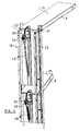
- FIG. 4 shows in a perspective view of the housing with the swung Duscharmen 8, 9 from behind.
- a drive 18 is provided which is housed in the housing 1 of the shower device.
- Each drive 18 includes a helical tension spring 19 which engages with a lever gear 20 on the shower arm 8, 9.
- Both Duscharme 8, 9 are mounted in the illustrated embodiment, each with a pivot bearing 21 in rails of the housing 1. The drive 18 engages on the shower head facing away from the shower arm 8, 9.
- a respective toothed disc 22 are housed stationary, along which a toothed wheel meshing with this gear 23 is moved.
- a rotary damper 24 is operatively connected.
- a feed line 25 leads to the pivot bearing 21. Through this supply line and through the pivot bearing 21, the water enters the interior of the shower arm 8 and from there through the shower head to the outside.
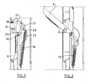
- FIGS. 5 and 6 show the arrangement of the middle shower arm 9, in FIG. 5 in the inactive position and in FIG. 6 in the use position.
- the pivot bearing of the shower arm 9 is given in point 21.
- a lever linkage 27 is articulated at 26, whose other end is connected to the free end 28 of the helical compression spring 19.
- the gear 23 is mounted, which rolls along the ring gear 22. It is guided via a link 29 which is mounted on the housing at 30. After the rolling of the gear 23 along the ring gear 22 of the shower arm 9 reaches the upper end positions, in FIG. 6 is shown.
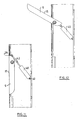
- FIG. 7 In the aborted depiction of FIG. 7 is the pivot bearing for the Duscharme 8, 9, 10 shown.
- An angle element 31 is seated at the upper end of the line 25. This angle element 31 projects with its one leg into the interior of the shower arm 8. There, a part of the water guide 32 is arranged for the shower head within the shower arm 8 and fluidly connected to this inner leg of the elbow 31.
- a nozzle 33 is fixed in a rail of the housing 1, in which a projection 34 is inserted from the inside.
- This approach 34 has an eccentric pin 35 which engages in the socket 33. It can be rotated by inserting a key into the key recess 36, so that the eccentricity relative to the nozzle 33 changes in position. In this way, the left end of the bearing shaft for the shower arm 8 can be displaced upwards or downwards, forwards or backwards. This is useful to make the parallelism of the edges of the visible outside 15 of the Duscharme with the side walls of the housing.
- FIG. 8 shows that at the angle piece a locking lug 37 is formed with two wings, which in the position of the FIG. 8 can be used in the rail.
- the side wings enter the lateral grooves of the slot, so that now the elbow 31 is locked, see FIG. 9 , Now, from below, the line end of the line 25 can be used in the approach.
- FIGS. 11 and 12 show the FIGS. 11 and 12 the use of a gas spring 40 for the same purpose.
- the gas spring 40 pulls the piston rod 42 inwards and thereby pivots the shower arm 9 in the clockwise direction FIGS. 11 and 12 outward.
- movement of the shower charm out of the housing is pivotal about a fixed axis.
- This has the advantage of a very simple water supply to the interior of the Duscharme.
Abstract
Description
Die Erfindung betrifft eine Duscheinrichtung mit mindestens einem Brausekopf.The invention relates to a shower device with at least one shower head.
Es ist ein Duschsystem bekannt (
Der Erfindung liegt die Aufgabe zu Grunde, eine Duscheinrichtung zu schaffen, die im nicht benutzten Zustand keine wesentlich vorspringenden Teile aufweist und die sich mit geringem Aufwand in einen gebrauchsfähigen Zustand versetzen lässt.The invention is based on the object to provide a shower device that has no significant projecting parts in the unused state and can be put into a usable state with little effort.
Zur Lösung dieser Aufgabe schlägt die Erfindung eine Duscheinrichtung mit den im Anspruch 1 genannten Merkmalen vor. Weiterbildungen der Erfindung sind Gegenstand von Unteransprüchen.To solve this problem, the invention proposes a shower device with the features mentioned in
Die Duscheinrichtung enthält also ein Gehäuse, das beispielsweise an einer Wand in einer Duschzelle befestigt ist. An dem Gehäuse ist ein Duscharm angebracht, der dann, wenn die Duscheinrichtung nicht benutzt werden soll, eine inaktive Position aufweist, in der er mit der Oberfläche des Gehäuses im wesentlichen bündig verläuft. Er bildet also keine vorspringenden Teile. Um nun die Duscheinrichtung auch benutzen zu können, ist vorgesehen, dass der Duscharm durch Auslösen eines Antriebs in eine Gebrauchsposition überführt wird, in der die Strahlscheibe so angeordnet ist, dass ein Benutzer duschen kann.The shower device thus contains a housing which is fastened, for example, to a wall in a shower cubicle. On the housing a shower arm is mounted, which, when the shower device is not to be used, has an inactive position in which it is substantially flush with the surface of the housing. So it does not form projecting parts. In order to also be able to use the shower device, it is provided that the shower arm is transferred by triggering a drive in a use position in which the jet disk is arranged so that a user can take a shower.
In Weiterbildung der Erfindung kann vorgesehen sein, dass der erwähnte Antrieb nur dazu dient, den Duscharm aus der inaktiven in die Gebrauchsposition zu überführen. Die umgekehrte Bewegung des Duscharms, wenn der Benutzer also mit dem Duschen fertig ist, kann von dem Benutzer von Hand durchgeführt werden. Er schiebt oder schwenkt oder versetzt in sonstiger Weise den Duscharm wieder in seine inaktive Position.In a further development of the invention can be provided that the mentioned drive only serves to transfer the shower arm from the inactive to the use position. The reverse movement of the shower arm, so when the user is done with the shower, can be performed by the user by hand. He pushes or pivots or otherwise puts the shower arm back in its inactive position.
Insbesondere kann vorgesehen sein, dass der Antrieb für den Duscharm eine Feder aufweist, die in der inaktiven Position des Duscharms soweit gespannt ist, dass sie die zum Überführen des Duscharms in die Gebrauchsposition erforderliche Energie gespeichert aufweist. Zum Spannen der Feder dient die Rückwärtsbewegung, die von dem Benutzer der Duscheinrichtung von Hand durchgeführt wird.In particular, it can be provided that the drive for the shower arm has a spring which is stretched in the inactive position of the shower arm so far that it has stored the energy required for transferring the shower arm in the use position. For tensioning the spring is the backward movement, which is performed by the user of the shower device by hand.
Insbesondere kann dabei vorgesehen sein, dass der Antrieb eine Schraubenfeder aufweist. Diese lässt sich auf engem aber in einer Richtung langen Raum sehr günstig unterbringen. Darüberhinaus handelt es sich hier um einen Standardbauteil, das in unterschiedlichen Größen und Merkmalen ständig zur Verfügung steht.In particular, it can be provided that the drive has a helical spring. This can be accommodated in a narrow but in one direction long space very cheap. Moreover, this is a standard component, which is constantly available in different sizes and features.
Es ist ebenfalls möglich und wird von der Erfindung vorgeschlagen, dass der Antrieb eine Gasdruckfeder aufweist.It is also possible and is proposed by the invention that the drive has a gas spring.
Eine weitere im Rahmen der Erfindung liegende Möglichkeit für den Antrieb besteht darin, dass dieser durch Wasserdruck betätigbar ist.Another possibility for the drive lying within the scope of the invention is that it can be actuated by water pressure.
Gerade bei der Bewegung des Duscharms durch eine Feder könnte die Gefahr bestehen, dass der Duscharm zu plötzlich aus der inaktiven Position heraus fährt. Um dies zu vermeiden, kann erfindungsgemäß in Weiterbildung vorgesehen sein, dass der Antrieb eine Dämpfungseinrichtung aufweist, um das Herausfahren des Duscharms in die Gebrauchsposition zu verlangsamen.Especially with the movement of the shower arm by a spring could be the danger that the shower arm moves too suddenly out of the inactive position. To avoid this, can be provided according to the invention in a development that the drive has a damping device to slow the retraction of the shower arm in the use position.
Erfindungsgemäß kann in Weiterbildung vorgesehen sein, dass der Antrieb ein Hebelgetriebe und/oder ein Zahnradgetriebe aufweisen kann.According to the invention may be provided in a development that the drive can have a lever mechanism and / or a gear transmission.
Insbesondere kann vorgesehen sein, dass die Dämpfungseinrichtung einen Drehdämpfer aufweist, was dann, wenn beim Antrieb eine Drehbewegung auftritt, eine Dämpfung auf kleinem Raum ermöglicht.In particular, it can be provided that the damping device has a rotary damper, which then, when the drive rotational movement occurs, allows damping in a small space.
Dieser Drehdämpfer kann also insbesondere mit dem Hebelgetriebe und/oder mit dem Zahnradgetriebe verbunden sein.This rotary damper can thus be connected in particular to the lever mechanism and / or to the gear transmission.
Beispielsweise kann der Drehdämpfer über das Zahnradgetriebe mit dem Gehäuse verbunden sein.For example, the rotary damper can be connected to the housing via the toothed gearing.
Es kann vorgesehen sein, dass der Drehdämpfer eine Relativbewegung zum Gehäuse durchführt.It can be provided that the rotary damper performs a relative movement to the housing.
Der Antrieb dient dazu, den Duscharm in eine Gebrauchsposition zu bringen. Diese Gebrauchsposition kann vorher durch Einstellen von Anschlägen oder dergleichen festgelegt werden. Die Erfindung schlägt nun in Weiterbildung vor, dass der Benutzer den Duscharm gegenüber der Gebrauchsposition noch in beide Richtungen um einen bestimmten Betrag verändern kann, ohne dass dies der Antrieb verhindert.The drive is used to bring the shower arm in a use position. This use position can be previously set by setting stops or the like. The invention now suggests in training before that the user can still change the shower arm relative to the position of use in both directions by a certain amount, without this prevents the drive.
Für die inaktive Position des Duscharms kann eine Rastung vorgesehen sein, die dafür sorgt, dass der Duscharm dann tatsächlich bündig mit der Oberfläche des Gehäuses verläuft, ohne dass Einflüsse des Antriebs diese Position verändern können.For the inactive position of the shower arm a detent can be provided, which ensures that the shower arm then actually flush with the surface of the housing, without influences of the drive can change this position.
Zur Auslösung des Antriebs kann vorgesehen sein, dass dieser durch Betätigen des dem Duschkopf des Duscharms zugeordneten Absperrventils ausgelöst wird. Dies kann entweder eine spezielle Bewegung dieses Ventils sein, beispielsweise dadurch, dass der Benutzer auf den Betätigungsgriff dieses Ventils drückt oder an ihm zieht.To trigger the drive can be provided that this is triggered by actuation of the shower head of the shower arm associated shut-off valve. This can be either a special movement of this valve, for example, the fact that the user presses on the operating handle of this valve or pulls on him.
Eine andere Möglichkeit besteht darin, dass einfach durch das Öffnen dieses Absperrventils der Antrieb ausgelöst wird.Another possibility is that simply by opening this shut-off valve, the drive is triggered.
Wenn die Duscheinrichtung zusätzlich zu der am Duscharm angebrachten Brause noch eine weitere Brause, beispielsweise eine Handbrause aufweist, so gibt es ein Umstellerventil, das bestimmt, weiche der Brausen in Betrieb genommen wird. Hier kann nun in Weiterbildung der Erfindung vorgesehen sein, dass der Antrieb zum Ausfahren des Duscharms dadurch ausgelöst wird, dass der Benutzer den Hebel für das Umschaltventil auf die in dem Duscharm angeordnete Brause umschaltet. Hier kann auch vorgesehen sein, dass der Umschalthebel dieses Umschaltventils sich nach Benutzung wieder in eine neutrale Position zurückstellt. Dies kann ebenfalls durch das manuelle Zurückführen des Duscharms in die inaktive Position bewirkt werden.If the shower device in addition to the shower arm mounted on the shower still another shower, such as a hand shower, so there is a diverter valve, which determines the soft shower is put into operation. Here, it can now be provided in a further development of the invention that the drive for extending the shower arm is triggered by the fact that the user switches the lever for the change-over valve to the arranged in the shower arm shower. Here it can also be provided that the switching lever of this change-over valve returns to use after use again in a neutral position. This can also be accomplished by manually returning the shower arm to the inactive position.
Eine weitere besonders bevorzugte Möglichkeit zum Auslösen des Antriebs für den Duscharm besteht darin, dass der Benutzer auf den Duscharm in dessen inaktiver Position drückt, wodurch die Verrastung gelöst wird, so dass jetzt der Antrieb wirken kann. Derartige push-push Vorgänge sind bei elektrischen Schaltern üblich.Another particularly preferred way to trigger the drive for the shower arm is that the user on the Pushing shower arm in its inactive position, whereby the locking is released, so that now the drive can act. Such push-push operations are common in electrical switches.
In Weiterbildung der Erfindung kann vorgesehen sein, dass die Wasserzufuhr zu dem in dem Duscharm angeordneten Duschkopf durch die Lagerung des Duscharms an dem Gehäuse hindurch führt beziehungsweise erfolgt. Diese Lagerung kann so ausgebildet sein, dass keine außen sichtbaren Leitungsverbindungen vorhanden sind.In a further development of the invention can be provided that the water supply to the arranged in the shower head shower head leads through the storage of the shower arm on the housing through or takes place. This storage can be designed so that no externally visible cable connections are available.
Insbesondere kann in Weiterbildung der Erfindung vorgesehen sein, dass der Duscharm schwenkbar gelagert ist, und zwar vorzugsweise um eine horizontale Achse. In diesem Fall führt die Wasserzufuhr ohne sonstige Einrichtungen durch die Schwenkachse hindurch.In particular, it can be provided in a development of the invention that the shower arm is pivotally mounted, preferably about a horizontal axis. In this case, the water supply without other facilities through the pivot axis passes.
Um den bündigen Verlauf der Oberfläche des Duscharms in der Oberfläche des Gehäuses unter allen möglichen Bedingungen zu erreichen, kann erfindungsgemäß in Weiterbildung vorgesehen sein, dass die Lagerung des Duscharms mindestens einseitig mindestens in der Höhe vorstellbar ausgebildet ist. Gerade dann, wenn der Duscharm eine bestimmte Länge aufweist, können auch geringe Abweichungen von einem geraden Verlauf optisch störend wirken. Dies kann durch die Verstellbarkeit der Lagerung verhindert werden.In order to achieve the flush course of the surface of the shower arm in the surface of the housing under all possible conditions, can be provided according to the invention in a further development that the storage of the shower arm is formed at least on one side conceivable at least in height. Just when the shower arm has a certain length, even small deviations from a straight course can be visually disturbing. This can be prevented by the adjustability of the storage.
Erfindungsgemäß kann vorgesehen sein, dass der Duschkopf an oder in dem Duscharm so angeordnet ist, dass seine Strahlfläche in das Innere des Gehäuses gerichtet ist, in der inaktiven Position also nicht sichtbar ist. Die Oberfläche des Gehäuses kann einschließlich der Oberfläche des Duscharms glattflächig verlaufen.According to the invention it can be provided that the shower head is arranged on or in the shower arm so that its jet surface is directed into the interior of the housing, so in the inactive position is not visible. The surface of the housing may extend smoothly, including the surface of the shower arm.
Bei einer Schwenklagerung kann in Weiterbildung vorgesehen sein, dass der Antrieb auf der dem Duschkopf abgewandten Seite der die Schwenkachse bildende Schwenklagerung angreift, so dass weder in ausgefahrenem Zustand noch während des Ausfahrens der Antrieb sichtbar wird.In a pivotal mounting can be provided in a development that the drive on the side facing away from the shower head of the Swivel axle forming pivot bearing attacks, so that neither in the extended state nor during the extension of the drive is visible.
Erfindungsgemäß schlägt die Erfindung vor, den Duscharm so anzuordnen, dass der in ihm angeordnete Brausekopf als Kopfbrause dienen kann.According to the invention proposes to arrange the shower arm so that the shower head arranged in it can serve as overhead shower.
In Weiterbildung der Erfindung kann vorgesehen sein, dass ein zweiter etwas tiefer angeordneter Duscharm vorhanden ist, der im übrigen ebenfalls einen Antrieb aufweist, um ihn aus der inaktiven in die Gebrauchsposition zu überführen. Bei diesem zweiten Duscharm kann es sich um einen Duscharm handeln, der dann benutzt werden kann, wenn sich ein Benutzer beispielsweise nur von der Schulter abwärts duschen will, um seine Haare nicht nass zu machen.In a further development of the invention can be provided that a second slightly lower arranged shower arm is present, which also has a drive, moreover, to transfer it from the inactive to the use position. This second shower arm may be a shower arm that may be used when, for example, a user only wants to shower down from the shoulder to keep his hair from getting wet.
In Weiterbildung der Erfindung kann vorgesehen sein, dass im unteren Bereich des Gehäuses eine Fußstütze vorhanden ist, die sich in ähnlicher oder gleicher Weise aus dem Gehäuse heraus klappen lässt wie der Duscharm im mittleren und oberen Bereich.In a further development of the invention can be provided that in the lower part of the housing, a footrest is present, which can be folded out of the housing in a similar or the same way as the shower arm in the middle and upper area.
In nochmaliger Weiterbildung der Erfindung kann vorgesehen sein, dass auch im unteren Bereich des Gehäuses ein Duscharm vorhanden ist, bei dem dann in der Gebrauchsposition die Strahlfläche des Brausekopfs beispielsweise nach oben gerichtet ist. Denkbar ist allerdings auch hier, dass die Strahlfläche nach unten gerichtet ist. Es kann bei diesem unteren Duscharm vorgesehen sein, dass die Strahlfläche des an diesem Duscharm angebrachten Brausekopfs wahlweise nach oben oder nach unten gerichtet werden kann. Dies kann beispielsweise durch eine unterschiedliche Bewegung dieses Duscharms aus dem Gehäuse geschehen. So ist es beispielsweise denkbar, durch den erwähnten Druck auf den Duscharm in dessen oberem Bereich ein herausklappen nach unten mit der Strahlfläche nach oben und durch Druck auf den Duscharm im unteren Bereich ein herausklappen nach oben mit der Strahlfläche nach unten durchzuführen.In a further development of the invention can be provided that also in the lower part of the housing, a shower arm is present, in which then in the use position, the jet surface of the shower head is directed upwards, for example. However, it is also conceivable here that the jet surface is directed downwards. It may be provided in this lower shower arm, that the jet surface of the shower head mounted on this shower head can be directed either upwards or downwards. This can be done for example by a different movement of this shower arm from the housing. So it is conceivable, for example, by the mentioned pressure on the shower arm in its upper part fold out down with the jet surface facing upwards and by pushing down on the shower arm in the lower area, unfold a flap upwards with the jet face downwards.
In Weiterbildung der Erfindung kann vorgesehen sein, diesen Duscharm als Fußstütze auszubilden.In a further development of the invention can be provided to form this shower arm as a footrest.
In nochmaliger Weiterbildung der Erfindung kann vorgesehen sein, dass die Duscharme frei von Betätigungselementen für die Dusche selbst sind, dass also alle Betätigungselemente einschließlich von Umschaltventilen an dem Gehäuse angeordnet sind.In a further development of the invention can be provided that the Duscharme are free of actuators for the shower itself, so that all actuators including switching valves are arranged on the housing.
Weitere Merkmale, Einzelheiten und Vorzüge der Erfindung ergeben sich aus den Ansprüchen und der Zusammenfassung, deren beider Wortlaut durch Bezugnahme zum Inhalt der Beschreibung gemacht wird, der folgenden Beschreibung bevorzugter Ausführungsformen der Erfindung sowie anhand der Zeichnung. Hierbei zeigen:
Figur 1- eine Seitenansicht eines Gehäuses einer von der Erfindung vorgeschlagenen Duscheinrichtung in dem inaktiven Zustand;
Figur 2- die Ansicht der Duscheinrichtung der
Figur 1 Figur 3- eine Ansicht der Duscheinrichtung der
Figur 1 von links inFigur 1 Figur 4- eine perspektivische Ansicht der Duscheinrichtung von hinten;
Figur 5- eine Einzeleinsicht des Antriebs in der inaktiven Position;
Figur 6- den Antrieb in der geöffneten Stellung des Duscharms;
Figur 7- einen Schnitt durch die Schwenklagerung eines Duscharms;
Figur 8- eine Einzelansicht der Lagerung;
Figur 9- die
Ansicht der Figur 8 im verschwenkten Zustand; Figur 10- einen Schnitt durch die Lagerung des Duscharms;
- Figur 11
- eine der
Figur 5 entsprechende Darstellung mit einer Gasdruckfeder und Figur 12- die
der Figur 6 entsprechende Darstellung mit der Gasdruckfeder als Antrieb.
- FIG. 1
- a side view of a housing proposed by the invention shower device in the inactive state;
- FIG. 2
- the view of the shower facility the
FIG. 1 with extended shower arms; - FIG. 3
- a view of the shower facility the
FIG. 1 from the left inFIG. 1 , - FIG. 4
- a perspective view of the shower device from behind;
- FIG. 5
- a single view of the drive in the inactive position;
- FIG. 6
- the drive in the open position of the shower arm;
- FIG. 7
- a section through the pivotal mounting of a shower arm;
- FIG. 8
- a single view of the storage;
- FIG. 9
- the view of
FIG. 8 in the pivoted state; - FIG. 10
- a section through the storage of the shower arm;
- FIG. 11
- one of the
FIG. 5 corresponding representation with a gas spring and - FIG. 12
- the the
FIG. 6 corresponding representation with the gas spring as drive.
Unterhalb des gerade erwähnten heraus geschwenkten Duscharms 8 ist ein zweiter Duscharm 9 angeordnet, der etwas steiler verläuft als der obere Duscharm 8. Auch er weist auf seiner Innenseite 13 die Strahlaustrittsfläche 12 eines Brausekopfs auf.Below the just mentioned pivoted
Im Bereich des unteren Endes ist der dritte Duscharm 10 vorhanden, dessen Strahlscheibe 12 nach oben gerichtet ist. Dieser Duscharm 10 ist um eine Achse 14 verschwenkbar, die in der inaktiven Position am unteren Ende des Duscharms 10 angeordnet ist. Bei den oberen Duscharmen 8, 9 ist dies anders, dort ist die Schwenkachse am oberen Ende des Duscharms 8, 9 angeordnet.In the region of the lower end of the
Der untere Duscharm 10 kann dazu dienen, sich die Fußsohlen zu duschen, während der mittlere Duscharm 9 dazu dient, sich beispielsweise von den Schultern abwärts zu duschen. Zum Ansteuern der verschiedenen Brauseköpfe in den verschiedenen Duscharmen 8, 9, 10 dienen die bereits erwähnten Umschaltventile und Absperrventile 6, 7.The
Der untere Duscharm 10 ist im dargestellten Ausführungsbeispiel gleichzeitig als Fußstütze ausgebildet. Es ist ebenfalls möglich und liegt im Rahmen der Erfindung, eine solche Fußstütze wie einen Duscharm aus dem Gehäuse heraus bewegbar anzuordnen, ohne sie mit einem Duschkopf zu versehen.The
Die
In dem Gehäuse sind ortsfest jeweils eine Zahnscheibe 22 untergebracht, längs der ein mit diesem Zahnkranz kämmendes Zahnrad 23 bewegt wird. Mit dem Zahnrad 23 ist ein Drehdämpfer 24 wirkverbunden. Beim Öffnen der Duscharme rollt das Zahnrad 23 an dem Zahnkranz 22 ab und versetzt dadurch den Drehdämpfer in Drehbewegung, wobei diese Drehbewegung zum Abbremsen der Bewegung führt.In the housing, a respective
Rechts in
Einzelheiten dieser Anordnung gehen aus den
In der abgebrochenen Darstellung der
Auf der gegenüberliegenden Seite des Duscharms ist in einer Schiene des Gehäuses 1 ein Stutzen 33 befestigt, in den ein Ansatz 34 von der Innenseite her eingesteckt ist. Dieser Ansatz 34 weist einen exzentrischen Zapfen 35 auf, der in den Sutzen 33 eingreift. Er kann durch Einsetzen eines Schlüssels in die Schlüsselvertiefung 36 verdreht werden, so dass sich die Exzentrizität gegenüber dem Stutzen 33 in ihrer Position verändert. Auf diese Weise kann das linke Ende der Lagerungswelle für den Duscharm 8 nach oben oder unten, nach vorne oder nach hinten verlagert werden. Dies ist sinnvoll, um die Parallelität der Kanten der sichtbaren Außenseite 15 der Duscharme mit den Seitenwänden des Gehäuses herzustellen.On the opposite side of the shower arm a
Die
Die Lage der Fügel des Verriegelungsansatzes 37 geht aus dem Schnitt der
Während bei der bisher beschriebenen Ausführungsform, insbesondere unter Bezugnahme auf die
Zum Auslösen der jeweiligen Antriebe dient ein nicht dargestellter, aber im Stand der Technik bekannter Rastverschluss, der durch Drücken geöffnet und durch ein zweites Drücken beim Zurückführen wieder geschlossen wird.To trigger the respective drives is not shown, but known in the art snap lock, which is opened by pressing and closed by a second press when returning.
In den dargestellten Ausführungsformen ist die Bewegung der Duscharme aus dem Gehäuse heraus eine Schwenkbewegung um eine feste Achse. Dies hat den Vorteil einer sehr einfachen Wasserversorgung des Inneren der Duscharme. Es ist aber auch möglich, als Bewegung der Duscharme eine Schiebebewegung gegebenenfalls längs einer gebogenen Bahn vorzusehen, womit auch der Zweck erfüllt würde, die Duscharme aus einer nicht störenden inaktiven Position in eine in das Innere der Duschzelle ragende Gebrauchsposition zu bewegen.In the illustrated embodiments, movement of the shower charm out of the housing is pivotal about a fixed axis. This has the advantage of a very simple water supply to the interior of the Duscharme. But it is also possible to provide as movement of the Duscharme a sliding movement optionally along a curved path, whereby the purpose would be to move the Duscharme from a non-disturbing inactive position into a projecting into the interior of the shower cubicle use position.
Claims (24)
Applications Claiming Priority (1)
| Application Number | Priority Date | Filing Date | Title |
|---|---|---|---|
| DE102007003417A DE102007003417A1 (en) | 2007-01-16 | 2007-01-16 | shower facilities |
Publications (3)
| Publication Number | Publication Date |
|---|---|
| EP1947252A2 true EP1947252A2 (en) | 2008-07-23 |
| EP1947252A3 EP1947252A3 (en) | 2009-06-03 |
| EP1947252B1 EP1947252B1 (en) | 2013-03-13 |
Family
ID=39273346
Family Applications (1)
| Application Number | Title | Priority Date | Filing Date |
|---|---|---|---|
| EP08000430A Not-in-force EP1947252B1 (en) | 2007-01-16 | 2008-01-11 | Shower device |
Country Status (4)
| Country | Link |
|---|---|
| US (1) | US8104111B2 (en) |
| EP (1) | EP1947252B1 (en) |
| CN (1) | CN101229024B (en) |
| DE (1) | DE102007003417A1 (en) |
Cited By (1)
| Publication number | Priority date | Publication date | Assignee | Title |
|---|---|---|---|---|
| EP3372317A1 (en) * | 2017-03-09 | 2018-09-12 | Hansgrohe SE | Pivoting nozzle with fluid pressure driven pivot body |
Families Citing this family (8)
| Publication number | Priority date | Publication date | Assignee | Title |
|---|---|---|---|---|
| DE102010023686A1 (en) * | 2010-06-14 | 2011-12-15 | Grohe Ag | Shower device i.e. body shower device, for shower panel for targeted wetting of parts of body of showering person, has spray head swingable at holder and exhibiting two pivoting angle positions |
| US20150158047A1 (en) * | 2013-12-06 | 2015-06-11 | Masco Corporation Of Indiana | Adjustable height shower system |
| US10352025B2 (en) | 2016-04-29 | 2019-07-16 | Moen Incorporated | Plumbing fixture fitting with mounting system |
| US10376904B2 (en) * | 2017-07-24 | 2019-08-13 | Diane Jack | Head and shoulder showerhead system |
| US11105075B2 (en) | 2018-05-08 | 2021-08-31 | Delta Faucet Company | Adjustable height shower head assembly |
| US11337560B2 (en) * | 2019-03-04 | 2022-05-24 | Helen Of Troy Limited | Shower caddy |
| CN117797992A (en) * | 2020-09-14 | 2024-04-02 | 厦门松霖科技股份有限公司 | Lifting rod device with water outlet terminal and bathing device |
| CN112502492B (en) * | 2020-11-26 | 2024-01-30 | 浙江艾希德新材料科技有限公司 | Shower room capable of being flushed at different angles |
Citations (1)
| Publication number | Priority date | Publication date | Assignee | Title |
|---|---|---|---|---|
| DE29813597U1 (en) | 1998-07-17 | 1998-10-22 | Schoenborn Klaus | Shower system |
Family Cites Families (21)
| Publication number | Priority date | Publication date | Assignee | Title |
|---|---|---|---|---|
| US2898605A (en) * | 1955-07-13 | 1959-08-11 | Raymond C Pearson | Water powered retractable showerhead |
| US3716192A (en) * | 1971-05-27 | 1973-02-13 | Moist O Matic Division Of Toro | Extended range sprinkler head |
| US3884258A (en) * | 1972-08-10 | 1975-05-20 | Leonard E Mull | Retractable bathroom fixture |
| DE3600322A1 (en) * | 1986-01-08 | 1987-07-09 | Robert Lukesch | SHOWER CABIN TO SUPPORT BODY CARE |
| DE3718645C2 (en) * | 1986-08-22 | 1996-07-11 | Appeltshauser Georg Dipl Ing F | Seating |
| US4912783A (en) * | 1988-11-18 | 1990-04-03 | Shafer Steven E | Toilet lid closing device |
| JPH03110228A (en) * | 1989-09-25 | 1991-05-10 | Takagi Ind Co Ltd | Spouter for mixture of hot and cold water |
| US5369814A (en) * | 1993-07-19 | 1994-12-06 | Denys; Joseph H. | Automatic commode seat closing system |
| DE4442547C1 (en) * | 1994-11-30 | 1996-06-05 | Daimler Benz Ag | Locking device for a hinged vehicle flap |
| US5465435A (en) * | 1995-02-21 | 1995-11-14 | Malvaez; Laura A. | Shower step for shaving legs |
| US5604936A (en) * | 1995-09-28 | 1997-02-25 | Mausolf; Melvin J. | Self-lowering toilet seat |
| CA2192601C (en) * | 1996-12-11 | 1997-03-24 | Denis Carrier | Therapeutic surround shower |
| JP3482333B2 (en) | 1997-12-25 | 2003-12-22 | アルプス電気株式会社 | Rotary connector with angle detection function |
| DE20000618U1 (en) | 2000-01-15 | 2000-03-30 | Frank Wolfgang | Seating |
| DE20010748U1 (en) | 2000-05-12 | 2000-08-31 | Spiegels Gmbh & Co Kg | In a surface, in particular a table top, in a cutout which can be swiveled around fastening points and is at least partially folded out |
| DE10048987B4 (en) * | 2000-09-27 | 2014-07-17 | Grohe Ag | shower device |
| DE20211120U1 (en) * | 2002-07-23 | 2002-10-24 | Wanger Michael | Rotatable shower device |
| DE10253840A1 (en) | 2002-11-15 | 2004-06-09 | Hansgrohe Ag | Shower unit has longitudinally aligned installation unit with several nozzles on flat side and able to pivot about axis running across longitudinal direction |
| DE10253849A1 (en) * | 2002-11-15 | 2004-06-03 | Hansgrohe Ag | shower arrangement |
| US6934974B1 (en) * | 2004-02-12 | 2005-08-30 | William P. Pantos | Force adjustable toilet seat lifting and lowering mechanism |
| DE102004021314A1 (en) | 2004-04-30 | 2005-11-24 | Hailo-Werk Rudolf Loh Gmbh & Co. Kg | Ironing board incorporates at least one gas compression spring which, at least at one end, is located within the trestle zone |
-
2007
- 2007-01-16 DE DE102007003417A patent/DE102007003417A1/en not_active Withdrawn
-
2008
- 2008-01-11 EP EP08000430A patent/EP1947252B1/en not_active Not-in-force
- 2008-01-11 US US11/972,953 patent/US8104111B2/en not_active Expired - Fee Related
- 2008-01-16 CN CN200810009541.5A patent/CN101229024B/en not_active Expired - Fee Related
Patent Citations (1)
| Publication number | Priority date | Publication date | Assignee | Title |
|---|---|---|---|---|
| DE29813597U1 (en) | 1998-07-17 | 1998-10-22 | Schoenborn Klaus | Shower system |
Cited By (3)
| Publication number | Priority date | Publication date | Assignee | Title |
|---|---|---|---|---|
| EP3372317A1 (en) * | 2017-03-09 | 2018-09-12 | Hansgrohe SE | Pivoting nozzle with fluid pressure driven pivot body |
| RU2683095C1 (en) * | 2017-03-09 | 2019-03-26 | Хансгрое СЕ | Rotary shower device with rotary body moved by fluid pressure |
| US10751746B2 (en) | 2017-03-09 | 2020-08-25 | Hansgrohe Se | Swivel shower having a fluid pressure driven swivel body |
Also Published As
| Publication number | Publication date |
|---|---|
| US20080168600A1 (en) | 2008-07-17 |
| EP1947252A3 (en) | 2009-06-03 |
| US8104111B2 (en) | 2012-01-31 |
| EP1947252B1 (en) | 2013-03-13 |
| CN101229024A (en) | 2008-07-30 |
| DE102007003417A1 (en) | 2008-07-17 |
| CN101229024B (en) | 2013-03-27 |
Similar Documents
| Publication | Publication Date | Title |
|---|---|---|
| EP1947252B1 (en) | Shower device | |
| DE3926461C2 (en) | ||
| EP2710211B1 (en) | Actuating drive for a furniture flap | |
| AT502937B1 (en) | CABINET FURNITURE | |
| DE3812313A1 (en) | DOOR LOCK | |
| DE102005048564A1 (en) | Closing device in vehicles has latch and locking pawl with emergency actuator acting on bend area of elbow joint pairs to release rigid joint and pawl from latch if motor fails | |
| DE112017004511B4 (en) | Locking device | |
| DE10327997A1 (en) | Lock for doors or flaps on vehicles | |
| WO2013134797A1 (en) | Piece of furniture, in particular storage cabinet | |
| DE102017101559A1 (en) | threshold | |
| DE102008004917B4 (en) | Remote operator for actuating an electrical switch | |
| EP2255694B1 (en) | Coupling device, in particular for a furniture adjustment device | |
| DE102006018485B4 (en) | Joint arrangement for actuating a flap, in particular smoke exhaust flap | |
| EP3372317A1 (en) | Pivoting nozzle with fluid pressure driven pivot body | |
| EP2161399A2 (en) | Motor vehicle with mechanism to move a flap | |
| DE102007012208A1 (en) | Device for locking a pivotable component of a motor vehicle | |
| EP1103690A1 (en) | Fume venting device | |
| DE3244795A1 (en) | Pivoting device | |
| EP2597234A2 (en) | Blocking device for a door, preferably with a door closer | |
| DE102011012171B4 (en) | Carriage for a central channel cleaning device in a canal | |
| WO2009135473A1 (en) | Sectional door | |
| DE10301584B4 (en) | Device for the displaceable arrangement of a panel | |
| DE102005051447A1 (en) | Door lock for vehicle has toothed wheel connection for transmission of opening or closing movement of double bolt lock to snap locks on upper or lower ends of door | |
| EP2787137B1 (en) | Locking device | |
| DE4202061A1 (en) | Automatic vehicle handbrake adjuster controller |
Legal Events
| Date | Code | Title | Description |
|---|---|---|---|
| PUAI | Public reference made under article 153(3) epc to a published international application that has entered the european phase |
Free format text: ORIGINAL CODE: 0009012 |
|
| AK | Designated contracting states |
Kind code of ref document: A2 Designated state(s): AT BE BG CH CY CZ DE DK EE ES FI FR GB GR HR HU IE IS IT LI LT LU LV MC MT NL NO PL PT RO SE SI SK TR |
|
| AX | Request for extension of the european patent |
Extension state: AL BA MK RS |
|
| PUAL | Search report despatched |
Free format text: ORIGINAL CODE: 0009013 |
|
| AK | Designated contracting states |
Kind code of ref document: A3 Designated state(s): AT BE BG CH CY CZ DE DK EE ES FI FR GB GR HR HU IE IS IT LI LT LU LV MC MT NL NO PL PT RO SE SI SK TR |
|
| AX | Request for extension of the european patent |
Extension state: AL BA MK RS |
|
| 17P | Request for examination filed |
Effective date: 20091118 |
|
| 17Q | First examination report despatched |
Effective date: 20091214 |
|
| AKX | Designation fees paid |
Designated state(s): AT BE BG CH CY CZ DE DK EE ES FI FR GB GR HR HU IE IS IT LI LT LU LV MC MT NL NO PL PT RO SE SI SK TR |
|
| GRAP | Despatch of communication of intention to grant a patent |
Free format text: ORIGINAL CODE: EPIDOSNIGR1 |
|
| GRAS | Grant fee paid |
Free format text: ORIGINAL CODE: EPIDOSNIGR3 |
|
| RAP1 | Party data changed (applicant data changed or rights of an application transferred) |
Owner name: HANSGROHE SE |
|
| GRAA | (expected) grant |
Free format text: ORIGINAL CODE: 0009210 |
|
| AK | Designated contracting states |
Kind code of ref document: B1 Designated state(s): AT BE BG CH CY CZ DE DK EE ES FI FR GB GR HR HU IE IS IT LI LT LU LV MC MT NL NO PL PT RO SE SI SK TR |
|
| REG | Reference to a national code |
Ref country code: GB Ref legal event code: FG4D Free format text: NOT ENGLISH |
|
| REG | Reference to a national code |
Ref country code: AT Ref legal event code: REF Ref document number: 600907 Country of ref document: AT Kind code of ref document: T Effective date: 20130315 Ref country code: CH Ref legal event code: EP |
|
| REG | Reference to a national code |
Ref country code: IE Ref legal event code: FG4D Free format text: LANGUAGE OF EP DOCUMENT: GERMAN |
|
| REG | Reference to a national code |
Ref country code: DE Ref legal event code: R096 Ref document number: 502008009435 Country of ref document: DE Effective date: 20130508 |
|
| PG25 | Lapsed in a contracting state [announced via postgrant information from national office to epo] |
Ref country code: SE Free format text: LAPSE BECAUSE OF FAILURE TO SUBMIT A TRANSLATION OF THE DESCRIPTION OR TO PAY THE FEE WITHIN THE PRESCRIBED TIME-LIMIT Effective date: 20130313 Ref country code: BG Free format text: LAPSE BECAUSE OF FAILURE TO SUBMIT A TRANSLATION OF THE DESCRIPTION OR TO PAY THE FEE WITHIN THE PRESCRIBED TIME-LIMIT Effective date: 20130613 Ref country code: ES Free format text: LAPSE BECAUSE OF FAILURE TO SUBMIT A TRANSLATION OF THE DESCRIPTION OR TO PAY THE FEE WITHIN THE PRESCRIBED TIME-LIMIT Effective date: 20130624 Ref country code: NO Free format text: LAPSE BECAUSE OF FAILURE TO SUBMIT A TRANSLATION OF THE DESCRIPTION OR TO PAY THE FEE WITHIN THE PRESCRIBED TIME-LIMIT Effective date: 20130613 Ref country code: LT Free format text: LAPSE BECAUSE OF FAILURE TO SUBMIT A TRANSLATION OF THE DESCRIPTION OR TO PAY THE FEE WITHIN THE PRESCRIBED TIME-LIMIT Effective date: 20130313 |
|
| REG | Reference to a national code |
Ref country code: NL Ref legal event code: VDEP Effective date: 20130313 |
|
| REG | Reference to a national code |
Ref country code: LT Ref legal event code: MG4D |
|
| PG25 | Lapsed in a contracting state [announced via postgrant information from national office to epo] |
Ref country code: FI Free format text: LAPSE BECAUSE OF FAILURE TO SUBMIT A TRANSLATION OF THE DESCRIPTION OR TO PAY THE FEE WITHIN THE PRESCRIBED TIME-LIMIT Effective date: 20130313 Ref country code: LV Free format text: LAPSE BECAUSE OF FAILURE TO SUBMIT A TRANSLATION OF THE DESCRIPTION OR TO PAY THE FEE WITHIN THE PRESCRIBED TIME-LIMIT Effective date: 20130313 Ref country code: SI Free format text: LAPSE BECAUSE OF FAILURE TO SUBMIT A TRANSLATION OF THE DESCRIPTION OR TO PAY THE FEE WITHIN THE PRESCRIBED TIME-LIMIT Effective date: 20130313 Ref country code: GR Free format text: LAPSE BECAUSE OF FAILURE TO SUBMIT A TRANSLATION OF THE DESCRIPTION OR TO PAY THE FEE WITHIN THE PRESCRIBED TIME-LIMIT Effective date: 20130614 |
|
| PG25 | Lapsed in a contracting state [announced via postgrant information from national office to epo] |
Ref country code: HR Free format text: LAPSE BECAUSE OF FAILURE TO SUBMIT A TRANSLATION OF THE DESCRIPTION OR TO PAY THE FEE WITHIN THE PRESCRIBED TIME-LIMIT Effective date: 20130313 |
|
| PG25 | Lapsed in a contracting state [announced via postgrant information from national office to epo] |
Ref country code: SK Free format text: LAPSE BECAUSE OF FAILURE TO SUBMIT A TRANSLATION OF THE DESCRIPTION OR TO PAY THE FEE WITHIN THE PRESCRIBED TIME-LIMIT Effective date: 20130313 Ref country code: NL Free format text: LAPSE BECAUSE OF FAILURE TO SUBMIT A TRANSLATION OF THE DESCRIPTION OR TO PAY THE FEE WITHIN THE PRESCRIBED TIME-LIMIT Effective date: 20130313 Ref country code: RO Free format text: LAPSE BECAUSE OF FAILURE TO SUBMIT A TRANSLATION OF THE DESCRIPTION OR TO PAY THE FEE WITHIN THE PRESCRIBED TIME-LIMIT Effective date: 20130313 Ref country code: PT Free format text: LAPSE BECAUSE OF FAILURE TO SUBMIT A TRANSLATION OF THE DESCRIPTION OR TO PAY THE FEE WITHIN THE PRESCRIBED TIME-LIMIT Effective date: 20130715 Ref country code: EE Free format text: LAPSE BECAUSE OF FAILURE TO SUBMIT A TRANSLATION OF THE DESCRIPTION OR TO PAY THE FEE WITHIN THE PRESCRIBED TIME-LIMIT Effective date: 20130313 Ref country code: IS Free format text: LAPSE BECAUSE OF FAILURE TO SUBMIT A TRANSLATION OF THE DESCRIPTION OR TO PAY THE FEE WITHIN THE PRESCRIBED TIME-LIMIT Effective date: 20130713 Ref country code: CZ Free format text: LAPSE BECAUSE OF FAILURE TO SUBMIT A TRANSLATION OF THE DESCRIPTION OR TO PAY THE FEE WITHIN THE PRESCRIBED TIME-LIMIT Effective date: 20130313 |
|
| PG25 | Lapsed in a contracting state [announced via postgrant information from national office to epo] |
Ref country code: PL Free format text: LAPSE BECAUSE OF FAILURE TO SUBMIT A TRANSLATION OF THE DESCRIPTION OR TO PAY THE FEE WITHIN THE PRESCRIBED TIME-LIMIT Effective date: 20130313 Ref country code: CY Free format text: LAPSE BECAUSE OF FAILURE TO SUBMIT A TRANSLATION OF THE DESCRIPTION OR TO PAY THE FEE WITHIN THE PRESCRIBED TIME-LIMIT Effective date: 20130313 |
|
| PLBE | No opposition filed within time limit |
Free format text: ORIGINAL CODE: 0009261 |
|
| STAA | Information on the status of an ep patent application or granted ep patent |
Free format text: STATUS: NO OPPOSITION FILED WITHIN TIME LIMIT |
|
| PG25 | Lapsed in a contracting state [announced via postgrant information from national office to epo] |
Ref country code: DK Free format text: LAPSE BECAUSE OF FAILURE TO SUBMIT A TRANSLATION OF THE DESCRIPTION OR TO PAY THE FEE WITHIN THE PRESCRIBED TIME-LIMIT Effective date: 20130313 |
|
| 26N | No opposition filed |
Effective date: 20131216 |
|
| PG25 | Lapsed in a contracting state [announced via postgrant information from national office to epo] |
Ref country code: IT Free format text: LAPSE BECAUSE OF FAILURE TO SUBMIT A TRANSLATION OF THE DESCRIPTION OR TO PAY THE FEE WITHIN THE PRESCRIBED TIME-LIMIT Effective date: 20130313 |
|
| REG | Reference to a national code |
Ref country code: DE Ref legal event code: R097 Ref document number: 502008009435 Country of ref document: DE Effective date: 20131216 |
|
| BERE | Be: lapsed |
Owner name: HANSGROHE SE Effective date: 20140131 |
|
| PG25 | Lapsed in a contracting state [announced via postgrant information from national office to epo] |
Ref country code: MC Free format text: LAPSE BECAUSE OF FAILURE TO SUBMIT A TRANSLATION OF THE DESCRIPTION OR TO PAY THE FEE WITHIN THE PRESCRIBED TIME-LIMIT Effective date: 20130313 Ref country code: LU Free format text: LAPSE BECAUSE OF FAILURE TO SUBMIT A TRANSLATION OF THE DESCRIPTION OR TO PAY THE FEE WITHIN THE PRESCRIBED TIME-LIMIT Effective date: 20140111 |
|
| REG | Reference to a national code |
Ref country code: CH Ref legal event code: PL |
|
| GBPC | Gb: european patent ceased through non-payment of renewal fee |
Effective date: 20140111 |
|
| PG25 | Lapsed in a contracting state [announced via postgrant information from national office to epo] |
Ref country code: LI Free format text: LAPSE BECAUSE OF NON-PAYMENT OF DUE FEES Effective date: 20140131 Ref country code: CH Free format text: LAPSE BECAUSE OF NON-PAYMENT OF DUE FEES Effective date: 20140131 |
|
| REG | Reference to a national code |
Ref country code: FR Ref legal event code: ST Effective date: 20140930 |
|
| REG | Reference to a national code |
Ref country code: IE Ref legal event code: MM4A |
|
| PG25 | Lapsed in a contracting state [announced via postgrant information from national office to epo] |
Ref country code: GB Free format text: LAPSE BECAUSE OF NON-PAYMENT OF DUE FEES Effective date: 20140111 Ref country code: FR Free format text: LAPSE BECAUSE OF NON-PAYMENT OF DUE FEES Effective date: 20140131 |
|
| PG25 | Lapsed in a contracting state [announced via postgrant information from national office to epo] |
Ref country code: BE Free format text: LAPSE BECAUSE OF NON-PAYMENT OF DUE FEES Effective date: 20140131 Ref country code: IE Free format text: LAPSE BECAUSE OF NON-PAYMENT OF DUE FEES Effective date: 20140111 |
|
| REG | Reference to a national code |
Ref country code: AT Ref legal event code: MM01 Ref document number: 600907 Country of ref document: AT Kind code of ref document: T Effective date: 20140111 |
|
| PG25 | Lapsed in a contracting state [announced via postgrant information from national office to epo] |
Ref country code: AT Free format text: LAPSE BECAUSE OF NON-PAYMENT OF DUE FEES Effective date: 20140111 |
|
| PG25 | Lapsed in a contracting state [announced via postgrant information from national office to epo] |
Ref country code: MT Free format text: LAPSE BECAUSE OF FAILURE TO SUBMIT A TRANSLATION OF THE DESCRIPTION OR TO PAY THE FEE WITHIN THE PRESCRIBED TIME-LIMIT Effective date: 20130313 |
|
| PG25 | Lapsed in a contracting state [announced via postgrant information from national office to epo] |
Ref country code: HU Free format text: LAPSE BECAUSE OF FAILURE TO SUBMIT A TRANSLATION OF THE DESCRIPTION OR TO PAY THE FEE WITHIN THE PRESCRIBED TIME-LIMIT; INVALID AB INITIO Effective date: 20080111 Ref country code: TR Free format text: LAPSE BECAUSE OF FAILURE TO SUBMIT A TRANSLATION OF THE DESCRIPTION OR TO PAY THE FEE WITHIN THE PRESCRIBED TIME-LIMIT Effective date: 20130313 |
|
| PGFP | Annual fee paid to national office [announced via postgrant information from national office to epo] |
Ref country code: DE Payment date: 20180125 Year of fee payment: 11 |
|
| REG | Reference to a national code |
Ref country code: DE Ref legal event code: R119 Ref document number: 502008009435 Country of ref document: DE |
|
| PG25 | Lapsed in a contracting state [announced via postgrant information from national office to epo] |
Ref country code: DE Free format text: LAPSE BECAUSE OF NON-PAYMENT OF DUE FEES Effective date: 20190801 |