EP1946892A2 - Clé à chocs - Google Patents
Clé à chocs Download PDFInfo
- Publication number
- EP1946892A2 EP1946892A2 EP07022437A EP07022437A EP1946892A2 EP 1946892 A2 EP1946892 A2 EP 1946892A2 EP 07022437 A EP07022437 A EP 07022437A EP 07022437 A EP07022437 A EP 07022437A EP 1946892 A2 EP1946892 A2 EP 1946892A2
- Authority
- EP
- European Patent Office
- Prior art keywords
- drive shaft
- impact
- impact wrench
- switching ring
- impactor
- Prior art date
- Legal status (The legal status is an assumption and is not a legal conclusion. Google has not performed a legal analysis and makes no representation as to the accuracy of the status listed.)
- Granted
Links
- 230000033001 locomotion Effects 0.000 claims description 17
- 238000006073 displacement reaction Methods 0.000 claims description 4
- 230000035939 shock Effects 0.000 claims description 3
- 230000005540 biological transmission Effects 0.000 description 2
- 238000003780 insertion Methods 0.000 description 2
- 230000037431 insertion Effects 0.000 description 2
- 230000000712 assembly Effects 0.000 description 1
- 238000000429 assembly Methods 0.000 description 1
- 238000010009 beating Methods 0.000 description 1
- 238000006243 chemical reaction Methods 0.000 description 1
- 230000002093 peripheral effect Effects 0.000 description 1
- 230000007704 transition Effects 0.000 description 1
Images


Classifications
-
- B—PERFORMING OPERATIONS; TRANSPORTING
- B25—HAND TOOLS; PORTABLE POWER-DRIVEN TOOLS; MANIPULATORS
- B25B—TOOLS OR BENCH DEVICES NOT OTHERWISE PROVIDED FOR, FOR FASTENING, CONNECTING, DISENGAGING OR HOLDING
- B25B21/00—Portable power-driven screw or nut setting or loosening tools; Attachments for drilling apparatus serving the same purpose
- B25B21/02—Portable power-driven screw or nut setting or loosening tools; Attachments for drilling apparatus serving the same purpose with means for imparting impact to screwdriver blade or nut socket
Definitions
- the invention relates to an impact wrench to non-impact mode switchable impact wrench, arranged with a motor driven drive shaft, a coaxial to the drive shaft, rotatably mounted relative to the drive shaft output shaft and a concentric to the drive shaft mounted on this, in driving connection with the drive shaft and by a spring force in Impact body acted upon in the axial direction to the output shaft, which is in rotational driving engagement with the output shaft in a forward position to the output shaft and connected by at least one cam arrangement and an engaging in this control with the drive shaft such that during impact operation of the shock body when on the Output shaft from the outside no counter-torque or a smaller counter-moment acts as a limit counter-moment, assumes its front position and, if on the output shaft from the outside, the limit Martinezmome nt, contrary to the spring force performs an axial movement to the rear with superimposed rotary motion relative to the drive shaft, rotates past the output shaft and then passes under the spring force back into its forward position and exerts a shock on the output shaft in
- Impact wrenches are used for tightening screws or loosening tightened screws.
- the impact wrench is attached to the respective screw and in operated according to the tightening or loosening corresponding direction of rotation, so that in the impact mode when the limit counter-torque occurs consecutive, pulse-like blows in the circumferential direction on the output shaft and thus exerted on the screw.
- a drive shaft in the axial direction enforcing switching pin is present, which is advanced to switch from the impact mode to the non-impact mode, so that it comes into rotationally fixed engagement with the output shaft and this directly rotatably connected to the drive shaft.
- the present invention has for its object to provide an impact wrench of the type mentioned, with a simple and stable structure and easy to handle manner of impact operation on the non-impact operation can be switched and allowed in non-impact operation, the transmission of relatively large torques.
- the impactor is locked in non-impact mode on the switching ring with the drive shaft, so that the impactor no longer rotate relative to the drive shaft and thus can not shift axially. Therefore, the impactor can no longer dodge as it were and get out of engagement with the output shaft when acting on the output shaft of the limiting counter-torque. Therefore, the output shaft is always connected rotationally fixed to the drive shaft.
- the switching ring may have a relatively large diameter, so that correspondingly large torques can be transmitted.
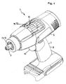
- the impact wrench 1 is designed as a cordless device.
- a receptacle for a battery pack is arranged at the bottom of the handle 7.
- the impact wrench could also be operated with mains power.
- a user-actuated push-button 10 is arranged at the front, via which a lying in the power supply operating switch 11 is actuated.
- the output shaft 5 is at the front of the device housing 6 in front of this and can be connected to a turning tool for screwing or unscrewing a screw.
- the protruding output shaft portion 12 is formed as a square shaft 13 and includes an outgoing from its front polygonal recess 14.
- a conventional socket wrench can be inserted non-rotatably having a polygonal receptacle for rotationally fixed insertion of a polygonal screw head.
- a socket wrench can also be attached to the square shank a header, on which in turn a turning tool can be set.
- the polygonal recess 14, however, can be used for the rotationally fixed insertion of a bit-like turning tool.
- the impact wrench 1 is switchable from a beating operation to a non-impact operation.
- the output shaft 5 is independent of the applied torque or regardless of the incoming or ausuformenden from the screw acting on the output shaft counter torque non-rotatably connected without interruption to the drive shaft, so that the impact wrench 1 works like a conventional screwdriver without impact function.
- the output shaft 5 can be selectively driven in both directions of rotation.
- the output shaft 5 is rotatably supported relative to the drive shaft 4.
- the drive shaft 4 on its output shaft 5 side facing a bearing extension 16 which engages in a bearing recess 15 of the output shaft 5 rotatably.
- the output shaft 5 is rotatably supported in the device housing 6 by means of a pivot bearing 17 arranged on its outer circumference.
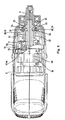
- the output shaft 5 also has at least one, advantageously a plurality of, in particular two diametrically opposed, radially outwardly projecting output drive projections 18, 19 (see in particular the FIGS. 2, 3 and 6 ), so that in the circumferential direction between the output driving projections 18, 19 spaces 20, 21 are formed.
- a concentric with the drive shaft 4 arranged impactor 22 is mounted, which is in a manner to be described in driving connection with the drive shaft 4, but it can perform on the drive shaft 4 an axial movement with superimposed rotary motion.
- the impactor 22 is acted upon by a spring force applied by a coil spring 23 in the direction of the output shaft 5 and takes except in the impact mode when acting on a counter-torque exceeding the counter-torque under the spring force to the output shaft 5 toward a forward forward position, which in the Drawing is shown. In this front position, the striker 22 is in rotational engagement with the output shaft 5.
- the striker 22 at its output shaft 5 facing end in the number of output driving projections 18, 19 of the output shaft 5 corresponding drive driving projections 24, 25, the protrude in the axial direction of the impactor body 22 and engage in the front position of the impactor body 22 in each case in one of the intermediate spaces 20, 21 between the output drive projections 18, 19.
- the driving entrainment projections 24, 25 have a smaller circumferential extent than the intermediate spaces 20, 21 between the driven entrainment projections 18, 19, so that the impactor body 22 and the output shaft 5 are relatively rotatable relative to one another. If the striking body is in its forward position, the driving entrainment projections 24, 25 lie in the direction of rotation of the drive shaft 4 on the driven entrainment projections 18, 19, so that the output shaft 5 is taken in the direction of rotation.
- the impactor body 22 and the drive shaft 4 are connected to each other via two diametrically opposite cam assemblies 26, 27, each with associated and in the respective control cam assembly 26, 27 engaging control 28, 29 in the form of a control ball 30, 31.
- two cam arrangements would suffice.
- each control cam arrangement 26, 27 has a V-shaped extending control groove 32 on the outer circumference of the drive shaft 4, in which the respective control ball 30, 31 engages.
- the tip of the V-shape of the cam groove 32 faces the output shaft 5.
- the respective control ball 30, 31 protrudes from the relevant control groove 32 of the drive shaft 4 and abuts a respective control surface 33 on the inner periphery of the impactor 22.
- FIG. 7 is the control surface 33 indicated by dash-dotted lines.
- the control surface 33 is formed on the inner circumference of the impactor body 22 at the transition to an extension 34, facing the output shaft 5, of the inner cross-section of the impactor body 22.
- the control surface 33 also has a V-shaped profile, wherein the tip of the V, however, faces away from the output shaft 5.
- a control groove corresponding course could be provided on the inner periphery of the impactor 22.
- the striking body 22 during impact operation when the output shaft 5 from the outside a larger counter-torque than the limit counter-torque is applied, against the spring force axial movement to the rear with superimposed Rotary movement relative to the drive shaft 4, so that the striking body 22 rotates past the output shaft 5 and then again under the spring force forward to the front position and thereby with its drive-driving projections 24, 25 in the spaces 20, 21 against the output driving projections 18, 19 of the output shaft 5 is moved, so that in the circumferential direction a blow to the output driving projections 18, 19 and thus exerted on the output shaft 5.
- a switching ring 35 is present, which can be actuated by means of an actuating device 36 from the outside and between an impact position associated with the inoperative position and the non-impact mode associated effective position.
- the switching ring 35 is arranged radially outside of the drive shaft 4 concentric with this.
- the switching ring 35 is rotatably mounted on a rotatably connected to the drive shaft 4 switching ring bearing part 37 and axially displaceable. In its inoperative position ( Figures 2 . 4 and 5 ) is the switching ring 35 away from the impactor 22, so that the impactor 22 is unaffected by the switching ring 35.
- the switching ring 35 moves you the switching ring 35, however, in its operative position to the impactor 22 back, the switching ring 35 comes into rotationally fixed locking engagement with the impactor 22.
- the switching ring 35 a plurality of distributed over the circumference, the impactor 22 projecting toward locking projections 38 on (in principle, only such a locking projection 38 could be present).
- Each locking projection 38 is assigned a arranged at the facing end of the impactor 22 locking recess 39.
- the locking projections 38 engage in the locking recesses 39, so that the striking body 22 is rotatably connected to the switching ring 35.
- the arrangement could also be made so that the locking projections on the striker and the locking recesses are arranged on the switching ring.
- Another advantage of the impact wrench 1 is that the impactor body 22 in the inoperative position of the switching ring 35 automatically off such a rotational position relative to the switching ring 35 assumes that the locking recesses 39 of the impactor 22 in the axial direction in alignment with the locking projections 38 of the switching ring 35 are arranged so that the switching ring 35 immediately enters his locking into the operative position with its locking projections 38 in the locking recesses 39 of the impactor body 22 and no further manipulations are required to bring the locking projections 38 and the locking recesses 39 in an aligned position.
- the end face regions 40, 41 of the striking body 22 arranged between two respective locking recesses 39 have a course which is recessed with respect to the mouths of the locking recesses 39, so that the aforementioned end face regions 40, 41 form depressions on the end face of the striking body 22. In this way it is avoided that the latching projections 38 of the switching ring 35 can collide with the end face of the impactor 22 in impact mode.
- the transmission unit 3 includes a drive shaft 4 driving planetary gear.
- this planetary gearset includes a set of planetary gears 42 distributed over the circumference, which radially inwardly mesh with a sun gear 43 driven by the drive motor 2 and radially outwardly with a ring gear 44 enclosing the set of planetary gears 42.
- the planetary gears 42 are each rotatably mounted on a Planetenradwelle 45 which project from an annular peripheral web body 46 which is arranged on the impactor 22 side facing the planetary gear 42.
- the drive shaft 4 is rotatably and axially fixedly connected to the web body 46, so that the drive shaft 4 is driven via the planetary gear.
- the planetary gear mechanism is a multi-stage, switchable planetary gear.
- the planetary gear mechanism has a web body facing the striking body 22, that is, the web body 46.
- This web body 46 is designed such that it also forms the switching ring bearing part 37.
- the switching ring 35 is rotatably mounted on the outer circumference of the web body 46 and axially displaceable. In this way, no separate switching ring bearing part is required, so that results in a low-part arrangement.
- the web body 46 has a smaller diameter than the impactor 22, so that the web body 46, as shown in FIGS. 4 and 5 it can be seen, a piece immersed in the impactor 22.
- groove-like, axially directed guideways 47 are arranged on the outer periphery of the web body 46.
- the arrangement is suitably made so that the locking projections 38 of the switching ring 35 run radially inward in the guideways 47 and engage in the non-impact operation with its radially outer region in the locking recesses 39 of the impactor body 22.
- the striker 22 acting on the front coil spring 23 is supported with its rear end on the web body 46, which is arranged fixed in the axial direction.
- the coil spring 23 rotates during operation of the impact wrench 1 with.
- the impactor 22 has an open towards the rear, annular circumferential recess 48 into which engages the coil spring 23 and is mounted with the respective end.
- the web body 46 also forms an annular circumferential recess 49, which is open towards the front and receives the rear end of the coil spring 23. This contributes to the space-saving design. In principle, only one of the two recesses 48, 49, expediently the recess 48 in the impactor 22, could be present.
- the actuating device 36 with which the switching ring 35 can be displaced, has an externally on the device housing 6 movably arranged actuating element 50, from the movement of the axial displacement movement of the switching ring 35 is derived.
- the switching ring 35 on its outer circumference on a circumferential annular groove 51 into which a suitably U-like switching bracket 52 engages, which preferably consists of wire material.
- the switch bracket 52 is movable in the axial direction and is actuated by means of the actuating element 50.
- the switching bracket 52 During operation of the impact wrench 1, the switching bracket 52 remains in the direction of rotation, and the switching ring 35 rotates past the switching bracket 52.
- the actuating element 50 is formed in the expedient embodiment of an annular, rotatably mounted on the housing 6 rotary valve 53 which is connected to the switch bracket 52 so that its rotational movement is converted into the axial displacement movement of the switching ring 35.
- This movement conversion takes place by means of a flat shape having deflecting part 54, on the one hand carries the switching bracket 52 and on the other hand with the rotary valve 53 in engagement is that the switching bracket 52 and with this the switching ring 35 moves in the axial direction when the rotary valve 53 is rotated.
Landscapes
- Engineering & Computer Science (AREA)
- Mechanical Engineering (AREA)
- Details Of Spanners, Wrenches, And Screw Drivers And Accessories (AREA)
Applications Claiming Priority (1)
| Application Number | Priority Date | Filing Date | Title |
|---|---|---|---|
| DE200710003037 DE102007003037A1 (de) | 2007-01-20 | 2007-01-20 | Schlagschrauber |
Publications (3)
| Publication Number | Publication Date |
|---|---|
| EP1946892A2 true EP1946892A2 (fr) | 2008-07-23 |
| EP1946892A3 EP1946892A3 (fr) | 2009-06-03 |
| EP1946892B1 EP1946892B1 (fr) | 2011-05-04 |
Family
ID=39284012
Family Applications (1)
| Application Number | Title | Priority Date | Filing Date |
|---|---|---|---|
| EP20070022437 Active EP1946892B1 (fr) | 2007-01-20 | 2007-11-20 | Clé à chocs |
Country Status (2)
| Country | Link |
|---|---|
| EP (1) | EP1946892B1 (fr) |
| DE (2) | DE102007003037A1 (fr) |
Cited By (5)
| Publication number | Priority date | Publication date | Assignee | Title |
|---|---|---|---|---|
| EP2168724A1 (fr) * | 2008-09-25 | 2010-03-31 | BLACK & DECKER INC. | Outil d'impact hybride |
| WO2012002578A1 (fr) * | 2010-06-30 | 2012-01-05 | Hitachi Koki Co., Ltd. | Outil à percussion |
| EP2476519A1 (fr) * | 2009-09-10 | 2012-07-18 | Positec Power Tools (Suzhou) Co., Ltd | Outil motorisé |
| CN106166722A (zh) * | 2015-05-22 | 2016-11-30 | 罗伯特·博世有限公司 | 具有机械式旋转冲击机构的手持式工具机 |
| CN112703087A (zh) * | 2018-07-27 | 2021-04-23 | 费斯托工具有限责任公司 | 手持式工具机器、尤其冲击式旋拧器 |
Families Citing this family (1)
| Publication number | Priority date | Publication date | Assignee | Title |
|---|---|---|---|---|
| DE102017101948A1 (de) | 2017-02-01 | 2018-08-02 | Festool Gmbh | Schlagschrauber |
Citations (1)
| Publication number | Priority date | Publication date | Assignee | Title |
|---|---|---|---|---|
| EP1050381A2 (fr) | 1999-04-30 | 2000-11-08 | Matsushita Electric Works, Ltd. | Outil à chocs rotatif |
Family Cites Families (4)
| Publication number | Priority date | Publication date | Assignee | Title |
|---|---|---|---|---|
| JP2828640B2 (ja) * | 1988-11-15 | 1998-11-25 | 松下電工株式会社 | 回転衝撃工具 |
| DE4301610C2 (de) * | 1993-01-22 | 1996-08-14 | Bosch Gmbh Robert | Schlagschrauber |
| JP4405900B2 (ja) * | 2004-03-10 | 2010-01-27 | 株式会社マキタ | インパクトドライバ |
| US20060237205A1 (en) * | 2005-04-21 | 2006-10-26 | Eastway Fair Company Limited | Mode selector mechanism for an impact driver |
-
2007
- 2007-01-20 DE DE200710003037 patent/DE102007003037A1/de not_active Withdrawn
- 2007-11-20 EP EP20070022437 patent/EP1946892B1/fr active Active
- 2007-11-20 DE DE200750007112 patent/DE502007007112D1/de active Active
Patent Citations (1)
| Publication number | Priority date | Publication date | Assignee | Title |
|---|---|---|---|---|
| EP1050381A2 (fr) | 1999-04-30 | 2000-11-08 | Matsushita Electric Works, Ltd. | Outil à chocs rotatif |
Cited By (10)
| Publication number | Priority date | Publication date | Assignee | Title |
|---|---|---|---|---|
| EP2168724A1 (fr) * | 2008-09-25 | 2010-03-31 | BLACK & DECKER INC. | Outil d'impact hybride |
| EP2476519A1 (fr) * | 2009-09-10 | 2012-07-18 | Positec Power Tools (Suzhou) Co., Ltd | Outil motorisé |
| EP2476519A4 (fr) * | 2009-09-10 | 2013-10-23 | Positec Power Tools Suzhou Co | Outil motorisé |
| WO2012002578A1 (fr) * | 2010-06-30 | 2012-01-05 | Hitachi Koki Co., Ltd. | Outil à percussion |
| CN102971113A (zh) * | 2010-06-30 | 2013-03-13 | 日立工机株式会社 | 冲击工具 |
| CN102971113B (zh) * | 2010-06-30 | 2015-03-25 | 日立工机株式会社 | 冲击工具 |
| US9522461B2 (en) | 2010-06-30 | 2016-12-20 | Hitachi Koki Co., Ltd. | Impact tool |
| CN106166722A (zh) * | 2015-05-22 | 2016-11-30 | 罗伯特·博世有限公司 | 具有机械式旋转冲击机构的手持式工具机 |
| CN112703087A (zh) * | 2018-07-27 | 2021-04-23 | 费斯托工具有限责任公司 | 手持式工具机器、尤其冲击式旋拧器 |
| US11986929B2 (en) | 2018-07-27 | 2024-05-21 | Festool Gmbh | Handheld machine tool, in particular impact driver |
Also Published As
| Publication number | Publication date |
|---|---|
| DE102007003037A1 (de) | 2008-07-24 |
| EP1946892A3 (fr) | 2009-06-03 |
| EP1946892B1 (fr) | 2011-05-04 |
| DE502007007112D1 (de) | 2011-06-16 |
Similar Documents
| Publication | Publication Date | Title |
|---|---|---|
| DE2825022C2 (fr) | ||
| EP0804315B1 (fr) | Machine-outil | |
| DE2620176C2 (de) | Zusatzvorrichtung zum Bohren und Schrauben für tragbare kraftbetriebene Werkzeuge | |
| DE102007019434B4 (de) | Handwerkzeugmaschine, insbesondere Bohr- oder Schraubgerät, mit Mikroschalter | |
| EP0108411B1 (fr) | Machine à percer | |
| DE3918227C1 (fr) | ||
| DE2219658C3 (de) | Kraftgetriebenes Werkzeug | |
| EP2262601B1 (fr) | Machine-outil a main | |
| DE102015205122B4 (de) | Schraubendreher | |
| EP1946892B1 (fr) | Clé à chocs | |
| EP0494400A2 (fr) | Outil à main avec porte-outil détachable | |
| DE102006054190A1 (de) | Werkzeugratsche | |
| DE2715357A1 (de) | Werkzeugaufnahmevorrichtung | |
| CH664715A5 (de) | Spannfutter fuer ein werkzeug, insbesondere zum schlagbohren. | |
| DE19528924B4 (de) | Elektrische Schlagbohrmaschine | |
| DE2557118C2 (de) | Tragbare Drehschlag-Maschinen mit ausrastbarem Schlagwerk | |
| EP1621290B1 (fr) | Machine-outil avec impulsion intermittent | |
| DE102012202278A1 (de) | Handwerkzeugmaschine | |
| DE3316111A1 (de) | Elektrohandwerkzeug mit steuerung fuer verschiedene funktionen | |
| DE102010009917A1 (de) | Schraubvorsatz und damit ausgestattetes Schraubgerät | |
| EP3862119B1 (fr) | Mandrin à changement rapide pour le blocage réversible d'un outil d'insertion sur un appareil d'usinage | |
| EP0239670A2 (fr) | Machine motorisée avec réglage du couple, en particulier outillages électriques | |
| EP0612589B1 (fr) | Dispositif de commande pour outils électriques | |
| DE4439590C2 (de) | Handwerkzeugmaschine | |
| EP4126457A1 (fr) | Outil permettant de comprimer et/ou de dilater une section de tuyau |
Legal Events
| Date | Code | Title | Description |
|---|---|---|---|
| PUAI | Public reference made under article 153(3) epc to a published international application that has entered the european phase |
Free format text: ORIGINAL CODE: 0009012 |
|
| AK | Designated contracting states |
Kind code of ref document: A2 Designated state(s): AT BE BG CH CY CZ DE DK EE ES FI FR GB GR HU IE IS IT LI LT LU LV MC MT NL PL PT RO SE SI SK TR |
|
| AX | Request for extension of the european patent |
Extension state: AL BA HR MK RS |
|
| PUAL | Search report despatched |
Free format text: ORIGINAL CODE: 0009013 |
|
| AK | Designated contracting states |
Kind code of ref document: A3 Designated state(s): AT BE BG CH CY CZ DE DK EE ES FI FR GB GR HU IE IS IT LI LT LU LV MC MT NL PL PT RO SE SI SK TR |
|
| AX | Request for extension of the european patent |
Extension state: AL BA HR MK RS |
|
| 17P | Request for examination filed |
Effective date: 20090516 |
|
| AKX | Designation fees paid |
Designated state(s): CH DE FR GB IT LI NL |
|
| GRAP | Despatch of communication of intention to grant a patent |
Free format text: ORIGINAL CODE: EPIDOSNIGR1 |
|
| GRAS | Grant fee paid |
Free format text: ORIGINAL CODE: EPIDOSNIGR3 |
|
| GRAA | (expected) grant |
Free format text: ORIGINAL CODE: 0009210 |
|
| AK | Designated contracting states |
Kind code of ref document: B1 Designated state(s): CH DE FR GB IT LI NL |
|
| REG | Reference to a national code |
Ref country code: GB Ref legal event code: FG4D Free format text: NOT ENGLISH |
|
| REG | Reference to a national code |
Ref country code: CH Ref legal event code: NV Representative=s name: TROESCH SCHEIDEGGER WERNER AG Ref country code: CH Ref legal event code: EP |
|
| REF | Corresponds to: |
Ref document number: 502007007112 Country of ref document: DE Date of ref document: 20110616 Kind code of ref document: P |
|
| REG | Reference to a national code |
Ref country code: DE Ref legal event code: R096 Ref document number: 502007007112 Country of ref document: DE Effective date: 20110616 |
|
| REG | Reference to a national code |
Ref country code: NL Ref legal event code: T3 |
|
| PLBE | No opposition filed within time limit |
Free format text: ORIGINAL CODE: 0009261 |
|
| STAA | Information on the status of an ep patent application or granted ep patent |
Free format text: STATUS: NO OPPOSITION FILED WITHIN TIME LIMIT |
|
| 26N | No opposition filed |
Effective date: 20120207 |
|
| REG | Reference to a national code |
Ref country code: DE Ref legal event code: R097 Ref document number: 502007007112 Country of ref document: DE Effective date: 20120207 |
|
| REG | Reference to a national code |
Ref country code: DE Ref legal event code: R082 Ref document number: 502007007112 Country of ref document: DE Representative=s name: PATENTANWAELTE MAGENBAUER & KOLLEGEN, DE |
|
| REG | Reference to a national code |
Ref country code: DE Ref legal event code: R081 Ref document number: 502007007112 Country of ref document: DE Owner name: FESTOOL GROUP GMBH & CO. KG, DE Free format text: FORMER OWNER: PROTOOL GMBH, 73240 WENDLINGEN, DE Effective date: 20121119 Ref country code: DE Ref legal event code: R082 Ref document number: 502007007112 Country of ref document: DE Representative=s name: PATENTANWAELTE MAGENBAUER & KOLLEGEN, DE Effective date: 20121119 Ref country code: DE Ref legal event code: R082 Ref document number: 502007007112 Country of ref document: DE Representative=s name: BREGENZER, MICHAEL, DIPL.-ING., DE Effective date: 20121119 Ref country code: DE Ref legal event code: R081 Ref document number: 502007007112 Country of ref document: DE Owner name: FESTOOL GMBH, DE Free format text: FORMER OWNER: PROTOOL GMBH, 73240 WENDLINGEN, DE Effective date: 20121119 Ref country code: DE Ref legal event code: R082 Ref document number: 502007007112 Country of ref document: DE Representative=s name: PATENTANWAELTE BREGENZER UND REULE PARTNERSCHA, DE Effective date: 20121119 |
|
| REG | Reference to a national code |
Ref country code: DE Ref legal event code: R082 Ref document number: 502007007112 Country of ref document: DE Representative=s name: BREGENZER, MICHAEL, DIPL.-ING., DE |
|
| REG | Reference to a national code |
Ref country code: DE Ref legal event code: R082 Ref document number: 502007007112 Country of ref document: DE Representative=s name: BREGENZER, MICHAEL, DIPL.-ING., DE Effective date: 20140918 Ref country code: DE Ref legal event code: R081 Ref document number: 502007007112 Country of ref document: DE Owner name: FESTOOL GMBH, DE Free format text: FORMER OWNER: FESTOOL GROUP GMBH & CO. KG, 73240 WENDLINGEN, DE Effective date: 20140918 Ref country code: DE Ref legal event code: R082 Ref document number: 502007007112 Country of ref document: DE Representative=s name: PATENTANWAELTE BREGENZER UND REULE PARTNERSCHA, DE Effective date: 20140918 |
|
| REG | Reference to a national code |
Ref country code: DE Ref legal event code: R082 Ref document number: 502007007112 Country of ref document: DE Representative=s name: PATENTANWAELTE BREGENZER UND REULE PARTNERSCHA, DE |
|
| PGFP | Annual fee paid to national office [announced via postgrant information from national office to epo] |
Ref country code: CH Payment date: 20141127 Year of fee payment: 8 |
|
| PGFP | Annual fee paid to national office [announced via postgrant information from national office to epo] |
Ref country code: NL Payment date: 20141030 Year of fee payment: 8 |
|
| PGFP | Annual fee paid to national office [announced via postgrant information from national office to epo] |
Ref country code: IT Payment date: 20141113 Year of fee payment: 8 |
|
| REG | Reference to a national code |
Ref country code: FR Ref legal event code: PLFP Year of fee payment: 9 |
|
| REG | Reference to a national code |
Ref country code: CH Ref legal event code: PL |
|
| PG25 | Lapsed in a contracting state [announced via postgrant information from national office to epo] |
Ref country code: CH Free format text: LAPSE BECAUSE OF NON-PAYMENT OF DUE FEES Effective date: 20151130 Ref country code: IT Free format text: LAPSE BECAUSE OF NON-PAYMENT OF DUE FEES Effective date: 20151120 Ref country code: LI Free format text: LAPSE BECAUSE OF NON-PAYMENT OF DUE FEES Effective date: 20151130 |
|
| REG | Reference to a national code |
Ref country code: NL Ref legal event code: MM Effective date: 20151201 |
|
| REG | Reference to a national code |
Ref country code: FR Ref legal event code: PLFP Year of fee payment: 10 |
|
| PG25 | Lapsed in a contracting state [announced via postgrant information from national office to epo] |
Ref country code: NL Free format text: LAPSE BECAUSE OF NON-PAYMENT OF DUE FEES Effective date: 20151201 |
|
| REG | Reference to a national code |
Ref country code: FR Ref legal event code: PLFP Year of fee payment: 11 |
|
| REG | Reference to a national code |
Ref country code: FR Ref legal event code: PLFP Year of fee payment: 12 |
|
| PGFP | Annual fee paid to national office [announced via postgrant information from national office to epo] |
Ref country code: FR Payment date: 20221007 Year of fee payment: 16 |
|
| PGFP | Annual fee paid to national office [announced via postgrant information from national office to epo] |
Ref country code: GB Payment date: 20221006 Year of fee payment: 16 Ref country code: DE Payment date: 20221013 Year of fee payment: 16 |
|
| P01 | Opt-out of the competence of the unified patent court (upc) registered |
Effective date: 20230517 |
|
| GBPC | Gb: european patent ceased through non-payment of renewal fee |
Effective date: 20231120 |