EP1946331B1 - Mirror for high power euv lamp system - Google Patents
Mirror for high power euv lamp system Download PDFInfo
- Publication number
- EP1946331B1 EP1946331B1 EP06806462A EP06806462A EP1946331B1 EP 1946331 B1 EP1946331 B1 EP 1946331B1 EP 06806462 A EP06806462 A EP 06806462A EP 06806462 A EP06806462 A EP 06806462A EP 1946331 B1 EP1946331 B1 EP 1946331B1
- Authority
- EP
- European Patent Office
- Prior art keywords
- mirror
- liquid
- opening
- aspheric surface
- euv
- Prior art date
- Legal status (The legal status is an assumption and is not a legal conclusion. Google has not performed a legal analysis and makes no representation as to the accuracy of the status listed.)
- Not-in-force
Links
Images


Classifications
-
- G—PHYSICS
- G03—PHOTOGRAPHY; CINEMATOGRAPHY; ANALOGOUS TECHNIQUES USING WAVES OTHER THAN OPTICAL WAVES; ELECTROGRAPHY; HOLOGRAPHY
- G03F—PHOTOMECHANICAL PRODUCTION OF TEXTURED OR PATTERNED SURFACES, e.g. FOR PRINTING, FOR PROCESSING OF SEMICONDUCTOR DEVICES; MATERIALS THEREFOR; ORIGINALS THEREFOR; APPARATUS SPECIALLY ADAPTED THEREFOR
- G03F7/00—Photomechanical, e.g. photolithographic, production of textured or patterned surfaces, e.g. printing surfaces; Materials therefor, e.g. comprising photoresists; Apparatus specially adapted therefor
- G03F7/70—Microphotolithographic exposure; Apparatus therefor
- G03F7/708—Construction of apparatus, e.g. environment aspects, hygiene aspects or materials
- G03F7/7095—Materials, e.g. materials for housing, stage or other support having particular properties, e.g. weight, strength, conductivity, thermal expansion coefficient
- G03F7/70958—Optical materials or coatings, e.g. with particular transmittance, reflectance or anti-reflection properties
-
- G—PHYSICS
- G03—PHOTOGRAPHY; CINEMATOGRAPHY; ANALOGOUS TECHNIQUES USING WAVES OTHER THAN OPTICAL WAVES; ELECTROGRAPHY; HOLOGRAPHY
- G03F—PHOTOMECHANICAL PRODUCTION OF TEXTURED OR PATTERNED SURFACES, e.g. FOR PRINTING, FOR PROCESSING OF SEMICONDUCTOR DEVICES; MATERIALS THEREFOR; ORIGINALS THEREFOR; APPARATUS SPECIALLY ADAPTED THEREFOR
- G03F7/00—Photomechanical, e.g. photolithographic, production of textured or patterned surfaces, e.g. printing surfaces; Materials therefor, e.g. comprising photoresists; Apparatus specially adapted therefor
- G03F7/70—Microphotolithographic exposure; Apparatus therefor
- G03F7/70008—Production of exposure light, i.e. light sources
- G03F7/70033—Production of exposure light, i.e. light sources by plasma extreme ultraviolet [EUV] sources
-
- G—PHYSICS
- G03—PHOTOGRAPHY; CINEMATOGRAPHY; ANALOGOUS TECHNIQUES USING WAVES OTHER THAN OPTICAL WAVES; ELECTROGRAPHY; HOLOGRAPHY
- G03F—PHOTOMECHANICAL PRODUCTION OF TEXTURED OR PATTERNED SURFACES, e.g. FOR PRINTING, FOR PROCESSING OF SEMICONDUCTOR DEVICES; MATERIALS THEREFOR; ORIGINALS THEREFOR; APPARATUS SPECIALLY ADAPTED THEREFOR
- G03F7/00—Photomechanical, e.g. photolithographic, production of textured or patterned surfaces, e.g. printing surfaces; Materials therefor, e.g. comprising photoresists; Apparatus specially adapted therefor
- G03F7/70—Microphotolithographic exposure; Apparatus therefor
- G03F7/70058—Mask illumination systems
- G03F7/7015—Details of optical elements
- G03F7/70175—Lamphouse reflector arrangements or collector mirrors, i.e. collecting light from solid angle upstream of the light source
-
- G—PHYSICS
- G03—PHOTOGRAPHY; CINEMATOGRAPHY; ANALOGOUS TECHNIQUES USING WAVES OTHER THAN OPTICAL WAVES; ELECTROGRAPHY; HOLOGRAPHY
- G03F—PHOTOMECHANICAL PRODUCTION OF TEXTURED OR PATTERNED SURFACES, e.g. FOR PRINTING, FOR PROCESSING OF SEMICONDUCTOR DEVICES; MATERIALS THEREFOR; ORIGINALS THEREFOR; APPARATUS SPECIALLY ADAPTED THEREFOR
- G03F7/00—Photomechanical, e.g. photolithographic, production of textured or patterned surfaces, e.g. printing surfaces; Materials therefor, e.g. comprising photoresists; Apparatus specially adapted therefor
- G03F7/70—Microphotolithographic exposure; Apparatus therefor
- G03F7/708—Construction of apparatus, e.g. environment aspects, hygiene aspects or materials
- G03F7/70908—Hygiene, e.g. preventing apparatus pollution, mitigating effect of pollution or removing pollutants from apparatus
- G03F7/70916—Pollution mitigation, i.e. mitigating effect of contamination or debris, e.g. foil traps
-
- G—PHYSICS
- G03—PHOTOGRAPHY; CINEMATOGRAPHY; ANALOGOUS TECHNIQUES USING WAVES OTHER THAN OPTICAL WAVES; ELECTROGRAPHY; HOLOGRAPHY
- G03F—PHOTOMECHANICAL PRODUCTION OF TEXTURED OR PATTERNED SURFACES, e.g. FOR PRINTING, FOR PROCESSING OF SEMICONDUCTOR DEVICES; MATERIALS THEREFOR; ORIGINALS THEREFOR; APPARATUS SPECIALLY ADAPTED THEREFOR
- G03F7/00—Photomechanical, e.g. photolithographic, production of textured or patterned surfaces, e.g. printing surfaces; Materials therefor, e.g. comprising photoresists; Apparatus specially adapted therefor
- G03F7/70—Microphotolithographic exposure; Apparatus therefor
- G03F7/708—Construction of apparatus, e.g. environment aspects, hygiene aspects or materials
- G03F7/70908—Hygiene, e.g. preventing apparatus pollution, mitigating effect of pollution or removing pollutants from apparatus
- G03F7/70925—Cleaning, i.e. actively freeing apparatus from pollutants, e.g. using plasma cleaning
-
- G—PHYSICS
- G21—NUCLEAR PHYSICS; NUCLEAR ENGINEERING
- G21K—HANDLING OF PARTICLES OR IONISING RADIATION NOT OTHERWISE PROVIDED FOR; IRRADIATION DEVICES; GAMMA RAY OR X-RAY MICROSCOPES
- G21K1/00—Arrangements for handling particles or ionising radiation, e.g. focusing or moderating
- G21K1/06—Arrangements for handling particles or ionising radiation, e.g. focusing or moderating using diffraction, refraction or reflection, e.g. monochromators
-
- H—ELECTRICITY
- H05—ELECTRIC TECHNIQUES NOT OTHERWISE PROVIDED FOR
- H05G—X-RAY TECHNIQUE
- H05G2/00—Apparatus or processes specially adapted for producing X-rays, not involving X-ray tubes, e.g. involving generation of a plasma
- H05G2/001—Production of X-ray radiation generated from plasma
- H05G2/002—Supply of the plasma generating material
-
- H—ELECTRICITY
- H05—ELECTRIC TECHNIQUES NOT OTHERWISE PROVIDED FOR
- H05G—X-RAY TECHNIQUE
- H05G2/00—Apparatus or processes specially adapted for producing X-rays, not involving X-ray tubes, e.g. involving generation of a plasma
- H05G2/001—Production of X-ray radiation generated from plasma
- H05G2/009—Auxiliary arrangements not involved in the plasma generation
Definitions
- the present disclosure relates to a system for providing extreme ultraviolet (EUV) radiation. Furthermore, the present invention relates to a mirror for harnessing EUV radiation.
- EUV extreme ultraviolet
- Radiation in the range 1 nm to 100 nm is typically produced using high-energy plasma discharges. These may be produced in an electrical discharge or in laser plasma, where a high power laser is focused onto a target material.
- a high power laser pulse When a high power laser pulse is incident on a material, for example, tin, highly ionised plasma is produced.
- the light output of this plasma depends on the laser wavelength, energy and pulse length, the target material and the target geometry.
- the optical (including EUV) emission is typically not isotropic from laser plasma.
- the crater being blown is of the order of 1 ⁇ m to 100 ⁇ m in depth per pulse, depending on the target material and laser power. As the pulse progresses, the walls of the crater obscure the EUV output from the base of the plasma.
- the vaporised material rises to further obscure the EUV emission from the plasma.
- EP1150169 disclose Xenon gas jets, which are typically used as laser plasma targets because Xe is a noble gas and does not form coatings on the surface of optical elements in the light source.
- Xenon jets have theoretical EUV conversion efficiencies about 3 times lower than tin at the required wavelength. Thus, a laser with 3 times the power would be required to achieve the same EUV output.
- US5459771 discloses the use of liquid droplets as laser plasma targets. These include doped water droplets and liquid metal targets.
- the water droplets are mixtures of materials that are designed to produce less debris than pure metals.
- liquid droplets are difficult to control, and produce a lower EUV output.
- reactive elements in the liquid cause contamination of source optics.
- US2002094063 discloses solid tapes as laser plasma targets, which may be comprised of any solid material with a very broad range of spectral outputs possible. However they produce a low conversion efficiency and difficulty of supplying 10 m/s of tape continuously for thousands of hours of operation.
- DE19743311 discloses the use of a liquid film, which is another renewable target type that is simpler than the droplet method.
- US2004264512 discloses a method of pre-pulsing, where a plasma is formed with a low intensity laser pulse above a target. This plasma is then used as a target for a second higher energy laser pulse and the resulting second plasma is optically thin, since the first plasma has lower than solid density. This increases the EUV output by reducing EUV self-absorption in the laser plasma. However this method still requires that the target be delivered in a way which will minimise subsequent loss.
- WO2004086467 discloses the use of target mixtures. Currently these include polymers with metal, metal and water and metal doped ceramics. However, most of these produce reactive debris and the target is not recoverable after it has been shot once.
- EP 1526550 discloses a mirror for use in a lithographic apparatus.
- DD230944 discloses a parabolic mirror for information retrieval brought into earth orbit, wherein the reflecting surface is generated i.a. by a flowing layer, preferably of mercury, on two counter rotating twin elements.
- EUV radiation sources will be required for the next generation lithography of semiconductor circuits. Intense research is ongoing to produce an EUV radiation source (13.5nm) with an output power of greater than 115 watts which can be used in high volume manufacturing. By providing a system with increased conversion efficiency (the output of EUV light energy per unit of input energy), this power level will be achieved cheaper and sooner.
- the present disclosure provides a system for providing EUV radiation.
- Some known systems for producing EUV use Mo/Si multilayer mirrors at normal incidence or Ru based single layer mirrors at a grazing angle, to try to harvest this radiation. These mirrors are produced with nanometer precision and are required to be almost atomically flat, making them extremely sensitive to debris from the plasma and erosion by high energy ions. In addition, current Mo/Si multilayers reflect in only a very specific window around 13.5 nm.
- optical elements are applied to the radiation to collect as much of the plasma produced EUV as possible.
- the collection optics are placed close to the EUV producing plasma and cover a large solid angle. It is nonetheless extremely difficult to protect the collecting optics from the plasma produced debris and high-energy ions.
- the present invention provides a mirror for harnessing EUV radiation as claimed in claim 1.
- the speed of rotation of said mirror is chosen to balance centrifugal and surface wetting forces to ensure a uniform coating of said liquid.
- the mirror of the present invention provides sufficient reflection efficiency, although not as high as the solid Mo/Si or Ru mirrors.
- the liquid reflection surface has advantages that will mean that it can outperform the other mirrors in terms of lifetime, cost and simplicity. These are key factors for any EUV radiation source in a high-volume manufacturing environment.
- the mirrors of the present invention can have a very broad reflectivity range, as different liquids can be used as well as different combinations of surfaces of revolution including elliptical, hyperbolic, parabolic and circular.
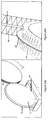
- the target delivery system 10 comprises a laser source (not shown) producing a beam 12 arranged to focus on a region of a sharp target edge 14 of a surface material to produce a highly ionised plasma 18, which in turn produces EUV emissions.
- the laser has a wavelength of 1064 nm and is pulsed with a pulse length preferably of approximately 15 nanoseconds and preferably with a pulse power density of approximately 1.6x10 11 Watts/cm 2 .
- a crater With this type of laser pulse focused onto a spot of 50 ⁇ m by 50 ⁇ m on a flat surface, as in the prior art, a crater would be formed in the target material of approximately 100 ⁇ m by 100 ⁇ m by 10 ⁇ m deep, depending on the target material properties.
- the EUV emissions produced are not obscured by crater formation in the target 14 or by material evaporated from the surface as there is little or no material in which crater walls can be formed or which can be boiled off, on at least one side of the plasma 18.
- the surface material is applied as a liquid metal coating to a blade 22.
- the surface of the blade 22 is formed of molybdenum.
- the blade 22 is formed on a carrier comprising a substantially wheel shaped roller 15 which is continuously rotated through a bath 24 containing the liquid metal, thereby coating the blade 22 with the liquid metal.
- the liquid metal is pure Tin (Sn).
- the liquid metal may be one of many alloys preferably of tin such as eutectic SnGa (Tin Gallium).
- the liquid will preferentially redistribute itself to conform to the edge of the blade 22.
- the thickness of the metal coating on the blade 22 is preferably of the order of a few microns.
- the roller 15 has a diameter of between about 30cm and 1m and preferably about 30cm and a thickness of about 1cm.
- the diameter of the wheel may be of any suitable value.
- the blade 22 has a base thickness of between approximately 100 ⁇ m to 1cm and preferably about 100 ⁇ m and a height of about 1cm.
- the plasma produced has a diameter of approximately 100 ⁇ m, which emits EUV radiation largely isotropically.
- the height of the blade 22 is chosen so as to ensure that the optical path of the EUV radiation emanating from the plasma is not obscured up to an emission angle 60 degrees from the optic axis so that as much of the EUV radiation can be harnessed as possible, as will be described in more detail later.
- a doctor blade 26 is disposed several centimetres before the laser focus region to regulate the coating thickness at the edge of the blade 22.
- the target edge can be pressed into a soft material or molten material as it hardens using a suitably shaped roller 16 or mould press, as illustrated in figures 2(a) and 2(b) .
- the roller 16 comprises a groove 17.
- the roller 16, rotating in the opposite direction, is pressed into the roller 15' and the groove 17 facilitates the formation of a blade 22' along the circumference of the roller 15 as the liquid metal hardens, thereby forming the sharp edge target.
- the generally triangular section blade 22 is replaced with a square profile blade (not shown) and the sharp target edge comprises one or both edges of the blade. Nonetheless, it will be appreciated that in this implementation, more of the EUV radiation is absorbed by the body of the blade than in the case of the blade 22. Thus, proportionally less EUV radiation is available for collection by for example the mirror system described below.
- a liquid mirror designed to bring to focus EUV radiation, preferably in the range 1nm to 100nm from the high temperature plasma 18.
- Materials reflect EUV radiation impinging on them at a shallow grazing incident angle. If the angle between the incident beam and the reflector is above a certain value, which depends on the material reflecting and the wavelength being reflected, then the reflected EUV intensity drops to near zero. In order to collect as much of the radiation emanating from the plasma source 18 as possible, the highest possible solid angle should be subtended by a collector with respect to the plasma source.
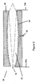
- a mirror 28 comprising a rotating metal cylinder 30, from which a substantially ellipsoidal surface 32 has been machined.
- the ellipsoidal surface 32 acts to focus rays 31 from one focus of the ellipsoid to the other, as depicted in figure 3 .
- the ellipsoidal surface 32 acts as a focusing system for EUV photons from a high power plasma discharge or laser plasma source, typically 10kW to 30kW.
- the mirror 28 is manufactured from a material that: will not be attacked or dissolved by liquid gold or tin; is easily polished and prepared for wetting with mirror liquid; and is resistant to corrosion in the temperature range of interest (up to 550°C), - such as Molybdenum.
- the mirror is produced by coating the ellipsoidal surface 32 with an appropriate reflecting liquid 34, and in particular, low melting point liquid metals, alloys or low vapour pressure vacuum oils.
- the liquid is chosen so that it wets the surface 32 well as is discussed in more detail later on.
- the surface is prepared so that it is wet well by the liquid chosen.
- the ellipsoidal shape 32 is preferable for two reasons. Firstly, it is desirable to keep the mirror 28 as far from the plasma 18 as possible without having a lens too large to rotate.
- the focal length of the mirror is chosen principally for reasons of thermal management.
- the optical properties of the ellipsoid shape remain reasonably constant as the focal length (distance between the object focus and image focus) is scaled up or down, providing the eccentricity remains constant.
- the eccentricity is chosen so as to achieve the maximum capture of EUV/Soft x-ray radiation from the plasma source, given that the plasma source 18 has finite dimensions between 100 ⁇ m and 1000 ⁇ m in diameter.
- the eccentricity of the ellipsoid 32 will be in the range 0.99809 to 0.98892. In the preferred embodiment, the eccentricity of the ellipsoid is around 0.99352.
- the reduction of reflectivity of the liquid 34 to approximately zero at a grazing angle greater than 40° and the reduction in intensity of most sources as a function of distance from the centre of the source means that very little is gained by having a numerical aperture greater than 0.81. This defines the start position of a particular lens relative to the source focal point.
- the source 18 is located 7.8mm in the direction of longitudinal axes from the mirror edge and the opening of the mirror is 26.8mm in diameter.
- a eutectic alloy such as Au80Sn20, is used as the mirror liquid 34.
- the melting point of this eutectic is 280°C. So, for a 986mm mirror, the volume of eutectic required for a 100micron coating is approximately 40cm3, and the mass of eutectic required for a 100 ⁇ m coating is approximately 0.625kg.
- Such a mirror liquid 34 will produce a mean reflectivity of approximately 40% over the grazing angles of interest, in the range of around 6° to 35°.
- the AuSn eutectic as the mirror liquid 34, it is possible to collect up to 13% of 13.5nm radiation emitted into 2n steradians by a source with a diameter of 1000 ⁇ m and to bring it to a focus of diameter 4mm with an image solid angle of 0.19 steradians and an etendue of 2.4 mm 2 sr.
- Another example of a reflecting liquid is Field's metal (32.5% Bi, 51% In, 16.5% Sn, MP 62°C) which has a reflectivity only marginally less than the AuSn eutectic, but has a much lower melting point and is much cheaper.
- Galinstan 68.5% Ga, 21.5% In, 10% Sn
- This may be particularly useful in hybrid systems described in relation to Figure 8 below.
- the mirror liquid 34 is injected into the mirror 28 through first and second hollow tubes 35a and 35b, which are static, separate from the mirror body, and connected to a metal pumping system (not shown).
- the outer diameter of the tubes 35a, and 35b, is preferably around 0.5mm.
- the tubes are made of a material, which will not be corroded by the mirror liquid, such as molybdenum.
- the material is capable of withstanding the temperature in proximity to the plasma.
- the mirror liquid 34 may be introduced into the mirror 28 by any suitable mechanism.
- the mirror liquid 34 is introduced to the mirror 28 through small bored holes located around 1cm along the cylinder length from the plasma end of the mirror 28.
- a system 37 comprising the target delivery system 10 and the mirror 28, according to the preferred embodiments of the present invention.
- the mirror 28 is rotated on four coaxial bearings 72, 74, 76 and 78, spaced along its length and thermally isolated from the cylinder 28, in order to uniformly coat the substrate with the liquid 34.
- the rate of rotation is around 0.5 to 2 revolutions per second. The purpose of the revolution is to allow a small pool of liquid at the base of the mirror 28 to replenish the coating of the mirror liquid 34 and to wash the surface 32 of the mirror 28 clean every revolution.
- This refreshing of the mirror 28 maintains the liquid coating on the surface 32 uniformly thick and as materially pure and optically flat as possible and ensures maintenance of the highest possible reflectivity for the mirror 28 in the EUV region required.
- the mirror liquid 34 may be periodically reformed or refreshed by several means such as new liquid flow or spray, recirculation, doctor blading, brushing, rolling or other mechanical resurfacing of the liquid.
- plasma 18 When plasma 18 is formed from the target edge 14, some of the surface material is sputtered off or evaporated. As the material expands away from the laser focus point, it cools and can be condensed on a cooler surface.
- the target 14 and one end of the mirror 28 are enveloped in a casing 38 with at least one opening 39 to allow the beam 12 to enter the casing 38 and strike the target edge 14 and allow for the collection and recycling of at least some of the laser ablated target material.
- the casing 38 extends around a groove 40 turned in the cylinder 30.
- the liquid metal bath 24 from which the surface material is drawn is in fluid communication with the cylinder 30, in such a way that the mirror 28 can be cooled using the same liquid as the surface material for the target edge, thereby forming a cooling system to efficiently recycle the surface material as explained in more detail below.
- a second casing 42 disposed around a turned groove 44 located in close proximity to the centre of the mirror 28 is provided to collect the excess mirror liquid draining from the bore hole 36.
- a third casing 46 disposed around a turned groove 48 located towards the end of the mirror 28 remote from the source 18 is provided to collect and condense any laser ablated target material or mirror liquid 34 coming from the end of the mirror.
- An opening 49 in the casing 46 is kept to a small size, preferably around 2mm, to block as much of the spluttered material as possible, while allowing for maximum EUV collection at the image focus.
- the second and third casings, 42 and 46 respectively preferably have operating liquid levels of below 50 millilitres. Preferably, the quantity of liquid will be sufficient to maintain the thermal contact required.
- Liquid may be supplied or drained from the casings 38, 42 and 46 as necessary via a drain pump.
- the temperature of the system 37 is managed by controlling the temperature of the liquid collected and recycled in the casings 38, 42, and 46.
- casing 46 is cooled across a large range of input plasma power, and preferably for power in excess of 15kW. This is achieved by attaching a water-cooling loop, indicated as 50 and 52, to the casing 46.
- the level of liquid metal 24 level in the first casing 38 is preferably kept at the minimum required to efficiently supply the surface material, preferably less than 100 millilitres. However, the quantity of liquid should also be sufficient to maintain good thermal contact between the rotating mirror cylinder 30 and the cooling system 50,52.
- the second and third casings 42 and 46 respectively require heating in order to maintain the temperature of the interior of the mirror 28 at a sufficiently high value so that the mirror liquid remains fluid. In the preferred embodiment, this is achieved by placing resistive heating elements 54, 56, and 58, 60 in thermal contact with the casings 42, 46 respectively. The liquid metal in the casings 42, 46 will maintain in efficient thermal contact between the heating elements and the body of the rotating mirror 28.
- a duplicate mirror system 62 positioned on the opposite side of the emitting plasma 18 from the first system 37, to harvest the EUV emitted from the other side of the plasma, thereby allowing a single EUV source to feed two separate systems, for example for use in lithography.
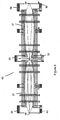
- the mirror system 28' comprises a known Wolter Type I structure having a plurality of concentric metal shells 80, as illustrated in figure 6 .
- the mirror shells are formed from suitable aspheric sections 82 such that the beam provided from the source undergoes two grazing angle reflections to arrive at the image focus.
- the aspheric sections 82 of this embodiment comprise a hyperboloid first reflector portion 88 followed by an ellipsoid second reflector portion 90.
- each of the reflectors 88 and 90 is approximately 250mm and the focal length of the mirror 28' is of the order of 2500mm to ensure the reflection angles are maintained as low as possible.
- the mirror liquid used in this embodiment may be liquid oil or liquid metal as is used in the preferred embodiment as described above.
- a liquid oil with optimal properties has a high reflectivity in the EUV and a high tolerance to the harsh conditions in proximity to the EUV producing plasma 18.
- the reflectivity of oils in the EUV range is largely dependent on the carbon content of the oil.
- liquid oil with a high atomic percentage of carbon is required, such as polyphenyl ethers, and preferably, C 30 H 22 O 4 .
- Polyphenyl ethers are preferred as they have a high resistance to attack by UV and ions. Furthermore, polyphenyl ethers have a boiling point of almost 300°C and the vapour pressure at 150°C is sufficiently low for absorption of the EUV by the vapour over the length of the mirror to be kept at an acceptable level (less than 10%).
- Vacuum oil reflectors have an advantage over liquid and solid metal reflectors, as they are transparent over a wide optical range and absorbing in the near ultraviolet. Furthermore, the oils have a lower reflectivity for 'out of band' radiation, which is more advantageous for imaging than the solid materials as used commonly.
- the material of the mirror 28' chosen depends on the choice of mirror liquid.
- the preferred mirror material is a metallic material which provides optimal wetting properties.
- any material that does not react with oil and has thermal properties which allow it to remain rigid and maintain its original shape at temperatures up to about 200°C (the upper end of the operational temperature range of oils) may be used as the mirror material.
- the preferred mirror material is molybdenum. Molybdenum is the preferred choice due to its high melting point, machinability, hardness, polishability as well as its resistance to the types of liquid metals and alloys suitable for use as the mirror liquid.
- the mirror 28' of the present embodiment comprises four shells 80-1, 80-2, 80-3, and 80-4. It will be appreciated however that any number of shells may be used.
- the shells 80 are fabricated from rigid metal and located concentrically around their optic axis and mounted on a spoked wheel 83 disposed at the end of the mirror remote from the plasma 18, Figure 7 .
- the spoked mounting wheel allows for a high degree of optical transmission through the mirror 28' while giving good mechanical support.
- the mirror liquid is introduced to the surface of these shells via four injection tubes 92-1, 92-2, 92-3 and 92-4, which are static and separate from the mirror sections 82.
- the tubes 92-1, 92-2, 92-3 and 92-4 are linked together at one end 94.
- a plurality of holes 96 are formed along the length of the tubes 92-1, 92-2, 92-3 and 92-4, and are fed from an external source (not shown) provided at end 94. It will however be appreciated that the tubes may not be linked and may be fed separately.
- the injection tubes have a diameter of approximately 3mm to mitigate the amount of light from the source being obscured by the tubes.
- the mirror 28' mounted on the spoked wheel is further mounted on spaced apart coaxial bearings 98 and 100 so that the mirror 28' can be rotated about its optical axis, as is illustrated in Figure 7 .
- the mirror 28' rotates at a rate of up to 200rpm (approximately 3 revolutions per second).
- the bearings are conductively isolated from the aspheric sections 82 using a ceramic insulating material.
- the revolution speed is such as to allow a small pool of liquid at the base of the mirror 28' to replenish the coating of the mirror liquid and to wash the aspheric sections 82 of the mirror 28' clean every revolution.
- the mirror liquid coating the surfaces of the shells 80-1, 80-2, 80-3 and 80-4, is preferentially spun towards the free end of the ellipsoid second reflector 90.
- the mirror may also be angled so as to increase this flow rate.
- a collection blade 110a is provided at the free end of the ellipsoid second reflector portion 90 to remove the excess liquid from the shells for recycling or reuse.
- a cooling effect is provided by the fact that the mirror liquid 34' is being replaced periodically or constantly by fresh liquid via the tubes 92-1, 92-2, 92-3 and 92-4.
- the cooling rate depends on the rate of liquid flow through the mirror 28', the thermal properties of the mirror liquid and its change in temperature.
- the mirror 28' of this embodiment may be used in conjunction with the target delivery system of Figure 1 to form a similar system as described above in relation to Figure 4 . Furthermore, the mirror 28' of this embodiment may be used to form a duplicate mirror system, as described above in relation to figure 5 .
- the mirror comprises a hybrid mirror system.
- the hybrid mirror system comprises a liquid mirror portion 110 disposed adjacent the plasma source as described in relation to the above embodiments and a solid coated mirror portion 120 disposed away from the plasma source.
- the portions 110 and 120 can be separated by a foil trap portion 130 which can remove much of the remaining debris from the plasma 18 or material sputtered from the liquid mirror 110.
- the mirror portion 120 is coated with ruthenium.
- the liquid mirror portion 110 protects the delicate, but higher reflectivity, ruthenium shell 120 from line of sight to the hot plasma 18 and from proximity to this heat source. This mirror design has higher overall efficiency than a pure liquid mirror shell and may offer a compromise between mirror lifetime and efficiency.
- the source aspects of the present disclosure and the mirror aspects of the present invention have many applications including but not limited to a light source for lithography, a light source for a microscope, and a focussing system for a telescope or a microscope.
Landscapes
- Physics & Mathematics (AREA)
- Engineering & Computer Science (AREA)
- General Physics & Mathematics (AREA)
- Public Health (AREA)
- Health & Medical Sciences (AREA)
- Epidemiology (AREA)
- Plasma & Fusion (AREA)
- Life Sciences & Earth Sciences (AREA)
- Environmental & Geological Engineering (AREA)
- Atmospheric Sciences (AREA)
- Optics & Photonics (AREA)
- Spectroscopy & Molecular Physics (AREA)
- General Engineering & Computer Science (AREA)
- High Energy & Nuclear Physics (AREA)
- X-Ray Techniques (AREA)
- Exposure Of Semiconductors, Excluding Electron Or Ion Beam Exposure (AREA)
- Optical Elements Other Than Lenses (AREA)
Applications Claiming Priority (2)
| Application Number | Priority Date | Filing Date | Title |
|---|---|---|---|
| IE20050730 | 2005-11-02 | ||
| PCT/EP2006/010187 WO2007051537A2 (en) | 2005-11-02 | 2006-10-23 | High power euv lamp system |
Publications (2)
| Publication Number | Publication Date |
|---|---|
| EP1946331A2 EP1946331A2 (en) | 2008-07-23 |
| EP1946331B1 true EP1946331B1 (en) | 2009-04-29 |
Family
ID=37564079
Family Applications (1)
| Application Number | Title | Priority Date | Filing Date |
|---|---|---|---|
| EP06806462A Not-in-force EP1946331B1 (en) | 2005-11-02 | 2006-10-23 | Mirror for high power euv lamp system |
Country Status (6)
| Country | Link |
|---|---|
| US (1) | US7763872B2 (https=) |
| EP (1) | EP1946331B1 (https=) |
| JP (1) | JP4901874B2 (https=) |
| AT (1) | ATE430369T1 (https=) |
| DE (1) | DE602006006589D1 (https=) |
| WO (1) | WO2007051537A2 (https=) |
Families Citing this family (20)
| Publication number | Priority date | Publication date | Assignee | Title |
|---|---|---|---|---|
| FR2904176A1 (fr) * | 2006-07-24 | 2008-01-25 | Xenocs Soc Par Actions Simplif | Systeme de delivrance de faisceau de rayons x stabilise |
| ATE551882T1 (de) * | 2007-09-07 | 2012-04-15 | Koninkl Philips Electronics Nv | Drehradelektrodenvorrichtung für gasentladungsquellen mit radabdeckung für hochleistungsbetrieb |
| EP2198675B1 (en) | 2007-09-07 | 2013-03-13 | Philips Intellectual Property & Standards GmbH | Electrode device for gas discharge sources and method of operating a gas discharge source having this electrode device |
| EP2215527A2 (en) | 2007-11-22 | 2010-08-11 | Philips Intellectual Property & Standards GmbH | Method of increasing the operation lifetime of a collector optics arranged in an irradiation device and corresponding irradiation device |
| NL1036613A1 (nl) * | 2008-03-03 | 2009-09-07 | Asml Netherlands Bv | Lithographic apparatus, plasma source, and reflecting method. |
| US20110039039A1 (en) * | 2008-04-30 | 2011-02-17 | University College Dublin, National University Of Ireland, Dublin | Wetting a surface of a solid substrate with a liquid metal |
| US8519367B2 (en) * | 2008-07-07 | 2013-08-27 | Koninklijke Philips N.V. | Extreme UV radiation generating device comprising a corrosion-resistant material |
| EP2157481A3 (en) * | 2008-08-14 | 2012-06-13 | ASML Netherlands B.V. | Radiation source, lithographic apparatus, and device manufacturing method |
| JP5577351B2 (ja) * | 2008-12-22 | 2014-08-20 | エーエスエムエル ネザーランズ ビー.ブイ. | リソグラフィ装置および放射システム |
| US8330131B2 (en) * | 2010-01-11 | 2012-12-11 | Media Lario, S.R.L. | Source-collector module with GIC mirror and LPP EUV light source |
| US8746975B2 (en) | 2011-02-17 | 2014-06-10 | Media Lario S.R.L. | Thermal management systems, assemblies and methods for grazing incidence collectors for EUV lithography |
| US8731139B2 (en) | 2011-05-04 | 2014-05-20 | Media Lario S.R.L. | Evaporative thermal management of grazing incidence collectors for EUV lithography |
| NL2010965A (en) | 2012-06-22 | 2013-12-24 | Asml Netherlands Bv | Radiation source and lithographic apparatus. |
| US9544984B2 (en) * | 2013-07-22 | 2017-01-10 | Kla-Tencor Corporation | System and method for generation of extreme ultraviolet light |
| JP6571092B2 (ja) | 2013-09-25 | 2019-09-04 | エーエスエムエル ネザーランズ ビー.ブイ. | ビームデリバリ装置及び方法 |
| RU2670273C2 (ru) * | 2017-11-24 | 2018-10-22 | Общество с ограниченной ответственностью "РнД-ИСАН" | Устройство и способ для генерации излучения из лазерной плазмы |
| US10613444B2 (en) * | 2018-08-28 | 2020-04-07 | Taiwan Semiconductor Manufacturing Co., Ltd. | Semiconductor apparatus and method of operating the same |
| US11968772B2 (en) * | 2019-05-30 | 2024-04-23 | Kla Corporation | Optical etendue matching methods for extreme ultraviolet metrology |
| JP7806584B2 (ja) * | 2022-03-30 | 2026-01-27 | ウシオ電機株式会社 | 光源装置 |
| JP2024179110A (ja) * | 2023-06-14 | 2024-12-26 | ウシオ電機株式会社 | 光源装置及び膜厚調整機構 |
Family Cites Families (9)
| Publication number | Priority date | Publication date | Assignee | Title |
|---|---|---|---|---|
| JPS55143502A (en) * | 1979-04-25 | 1980-11-08 | Toshikatsu Omiya | Production of paraboloid-of-revolution mirror |
| DD152168A1 (de) * | 1980-07-07 | 1981-11-18 | Ustinow Nikolai | Parabolspiegel zur energiegewinnung |
| DD230944A1 (de) * | 1983-11-15 | 1985-12-11 | Nikolai Ustinow | Parabolspiegel zur informationsgewinnung |
| JPH05343297A (ja) * | 1992-06-09 | 1993-12-24 | Matsushita Electron Corp | 露光方法および露光装置 |
| US7439530B2 (en) * | 2005-06-29 | 2008-10-21 | Cymer, Inc. | LPP EUV light source drive laser system |
| DE10138284A1 (de) * | 2001-08-10 | 2003-02-27 | Zeiss Carl | Beleuchtungssystem mit genesteten Kollektoren |
| JP4065528B2 (ja) * | 2003-03-10 | 2008-03-26 | キヤノン株式会社 | 恒温真空容器及びそれを用いた露光装置 |
| EP1624467A3 (en) * | 2003-10-20 | 2007-05-30 | ASML Netherlands BV | Lithographic apparatus and device manufacturing method |
| JP2006019510A (ja) * | 2004-07-01 | 2006-01-19 | Nikon Corp | 露光装置及びマイクロデバイスの製造方法 |
-
2006
- 2006-10-23 AT AT06806462T patent/ATE430369T1/de not_active IP Right Cessation
- 2006-10-23 US US12/083,361 patent/US7763872B2/en active Active
- 2006-10-23 DE DE602006006589T patent/DE602006006589D1/de active Active
- 2006-10-23 WO PCT/EP2006/010187 patent/WO2007051537A2/en not_active Ceased
- 2006-10-23 EP EP06806462A patent/EP1946331B1/en not_active Not-in-force
- 2006-10-23 JP JP2008538280A patent/JP4901874B2/ja not_active Expired - Fee Related
Also Published As
| Publication number | Publication date |
|---|---|
| EP1946331A2 (en) | 2008-07-23 |
| JP4901874B2 (ja) | 2012-03-21 |
| DE602006006589D1 (https=) | 2009-06-10 |
| US20090153975A1 (en) | 2009-06-18 |
| US7763872B2 (en) | 2010-07-27 |
| JP2009515326A (ja) | 2009-04-09 |
| ATE430369T1 (de) | 2009-05-15 |
| WO2007051537A3 (en) | 2007-07-19 |
| WO2007051537A2 (en) | 2007-05-10 |
Similar Documents
| Publication | Publication Date | Title |
|---|---|---|
| EP1946331B1 (en) | Mirror for high power euv lamp system | |
| US7732794B2 (en) | Extreme ultra violet light source apparatus | |
| KR100358447B1 (ko) | 블라스트 실드를 갖춘 플라즈마 포커싱된 고 에너지 포톤소스 | |
| JP5368478B2 (ja) | レーザ生成プラズマ源の斜入射集光光学系 | |
| EP1047288B1 (en) | Plasma focus high energy photon source | |
| JP4320999B2 (ja) | X線発生装置及び露光装置 | |
| US7399981B2 (en) | Apparatus for generating light in the extreme ultraviolet and use in a light source for extreme ultraviolet lithography | |
| US8003962B2 (en) | Extreme ultraviolet light source apparatus and nozzle protection device | |
| TW200421040A (en) | Radiation source, lithographic apparatus, and device manufacturing method | |
| TW201127214A (en) | System, method and apparatus for laser produced plasma extreme ultraviolet chamber with hot walls and cold collector mirror | |
| WO2005047980A2 (en) | Monolithic silicon euv collector | |
| US6977383B2 (en) | Method and apparatus for generating a membrane target for laser produced plasma | |
| CN110658694B (zh) | 用于极紫外光辐射源设备的极紫外光收集器反射镜及极紫外光辐射源设备 | |
| KR101228776B1 (ko) | 집광경 어셈블리 및 이 집광경 어셈블리를 이용한 극단 자외광 광원 장치 | |
| JP3317957B2 (ja) | ブラストシールドを備えるプラズマフォーカス高エネルギフォトン源 | |
| TW202106117A (zh) | 汙染捕捉器 | |
| JP7798274B2 (ja) | 高輝度レーザ生成プラズマ源,ならびに放射生成および収集方法 | |
| JP6075096B2 (ja) | ホイルトラップおよびこのホイルトラップを用いた光源装置 | |
| EP1775756B1 (en) | Euv light source, euv exposure equipment and semiconductor device manufacturing method | |
| JP4618013B2 (ja) | 極端紫外光光源装置 | |
| Kubiak et al. | High-power source and illumination system for extreme ultraviolet lithography | |
| CN114995063A (zh) | 辐射源设备及其使用方法 | |
| JP2007129103A (ja) | 極端紫外光光源装置 | |
| WO2024201456A1 (en) | Short-wave systems and methods and suitable targets thereof |
Legal Events
| Date | Code | Title | Description |
|---|---|---|---|
| PUAI | Public reference made under article 153(3) epc to a published international application that has entered the european phase |
Free format text: ORIGINAL CODE: 0009012 |
|
| 17P | Request for examination filed |
Effective date: 20080602 |
|
| AK | Designated contracting states |
Kind code of ref document: A2 Designated state(s): AT BE BG CH CY CZ DE DK EE ES FI FR GB GR HU IE IS IT LI LT LU LV MC NL PL PT RO SE SI SK TR |
|
| GRAP | Despatch of communication of intention to grant a patent |
Free format text: ORIGINAL CODE: EPIDOSNIGR1 |
|
| RTI1 | Title (correction) |
Free format text: MIRROR FOR HIGH POWER EUV LAMP SYSTEM |
|
| GRAS | Grant fee paid |
Free format text: ORIGINAL CODE: EPIDOSNIGR3 |
|
| GRAA | (expected) grant |
Free format text: ORIGINAL CODE: 0009210 |
|
| AK | Designated contracting states |
Kind code of ref document: B1 Designated state(s): AT BE BG CH CY CZ DE DK EE ES FI FR GB GR HU IE IS IT LI LT LU LV MC NL PL PT RO SE SI SK TR |
|
| REG | Reference to a national code |
Ref country code: GB Ref legal event code: FG4D |
|
| REG | Reference to a national code |
Ref country code: CH Ref legal event code: EP |
|
| REF | Corresponds to: |
Ref document number: 602006006589 Country of ref document: DE Date of ref document: 20090610 Kind code of ref document: P |
|
| REG | Reference to a national code |
Ref country code: IE Ref legal event code: FG4D |
|
| PG25 | Lapsed in a contracting state [announced via postgrant information from national office to epo] |
Ref country code: LT Free format text: LAPSE BECAUSE OF FAILURE TO SUBMIT A TRANSLATION OF THE DESCRIPTION OR TO PAY THE FEE WITHIN THE PRESCRIBED TIME-LIMIT Effective date: 20090429 Ref country code: FI Free format text: LAPSE BECAUSE OF FAILURE TO SUBMIT A TRANSLATION OF THE DESCRIPTION OR TO PAY THE FEE WITHIN THE PRESCRIBED TIME-LIMIT Effective date: 20090429 Ref country code: AT Free format text: LAPSE BECAUSE OF FAILURE TO SUBMIT A TRANSLATION OF THE DESCRIPTION OR TO PAY THE FEE WITHIN THE PRESCRIBED TIME-LIMIT Effective date: 20090429 Ref country code: ES Free format text: LAPSE BECAUSE OF FAILURE TO SUBMIT A TRANSLATION OF THE DESCRIPTION OR TO PAY THE FEE WITHIN THE PRESCRIBED TIME-LIMIT Effective date: 20090809 Ref country code: PT Free format text: LAPSE BECAUSE OF FAILURE TO SUBMIT A TRANSLATION OF THE DESCRIPTION OR TO PAY THE FEE WITHIN THE PRESCRIBED TIME-LIMIT Effective date: 20090829 |
|
| PG25 | Lapsed in a contracting state [announced via postgrant information from national office to epo] |
Ref country code: SE Free format text: LAPSE BECAUSE OF FAILURE TO SUBMIT A TRANSLATION OF THE DESCRIPTION OR TO PAY THE FEE WITHIN THE PRESCRIBED TIME-LIMIT Effective date: 20090729 Ref country code: SI Free format text: LAPSE BECAUSE OF FAILURE TO SUBMIT A TRANSLATION OF THE DESCRIPTION OR TO PAY THE FEE WITHIN THE PRESCRIBED TIME-LIMIT Effective date: 20090429 Ref country code: IS Free format text: LAPSE BECAUSE OF FAILURE TO SUBMIT A TRANSLATION OF THE DESCRIPTION OR TO PAY THE FEE WITHIN THE PRESCRIBED TIME-LIMIT Effective date: 20090829 Ref country code: LV Free format text: LAPSE BECAUSE OF FAILURE TO SUBMIT A TRANSLATION OF THE DESCRIPTION OR TO PAY THE FEE WITHIN THE PRESCRIBED TIME-LIMIT Effective date: 20090429 Ref country code: PL Free format text: LAPSE BECAUSE OF FAILURE TO SUBMIT A TRANSLATION OF THE DESCRIPTION OR TO PAY THE FEE WITHIN THE PRESCRIBED TIME-LIMIT Effective date: 20090429 |
|
| PG25 | Lapsed in a contracting state [announced via postgrant information from national office to epo] |
Ref country code: RO Free format text: LAPSE BECAUSE OF FAILURE TO SUBMIT A TRANSLATION OF THE DESCRIPTION OR TO PAY THE FEE WITHIN THE PRESCRIBED TIME-LIMIT Effective date: 20090429 Ref country code: EE Free format text: LAPSE BECAUSE OF FAILURE TO SUBMIT A TRANSLATION OF THE DESCRIPTION OR TO PAY THE FEE WITHIN THE PRESCRIBED TIME-LIMIT Effective date: 20090429 Ref country code: CZ Free format text: LAPSE BECAUSE OF FAILURE TO SUBMIT A TRANSLATION OF THE DESCRIPTION OR TO PAY THE FEE WITHIN THE PRESCRIBED TIME-LIMIT Effective date: 20090429 Ref country code: DK Free format text: LAPSE BECAUSE OF FAILURE TO SUBMIT A TRANSLATION OF THE DESCRIPTION OR TO PAY THE FEE WITHIN THE PRESCRIBED TIME-LIMIT Effective date: 20090429 |
|
| PG25 | Lapsed in a contracting state [announced via postgrant information from national office to epo] |
Ref country code: BE Free format text: LAPSE BECAUSE OF FAILURE TO SUBMIT A TRANSLATION OF THE DESCRIPTION OR TO PAY THE FEE WITHIN THE PRESCRIBED TIME-LIMIT Effective date: 20090429 Ref country code: SK Free format text: LAPSE BECAUSE OF FAILURE TO SUBMIT A TRANSLATION OF THE DESCRIPTION OR TO PAY THE FEE WITHIN THE PRESCRIBED TIME-LIMIT Effective date: 20090429 |
|
| PLBE | No opposition filed within time limit |
Free format text: ORIGINAL CODE: 0009261 |
|
| STAA | Information on the status of an ep patent application or granted ep patent |
Free format text: STATUS: NO OPPOSITION FILED WITHIN TIME LIMIT |
|
| PG25 | Lapsed in a contracting state [announced via postgrant information from national office to epo] |
Ref country code: BG Free format text: LAPSE BECAUSE OF FAILURE TO SUBMIT A TRANSLATION OF THE DESCRIPTION OR TO PAY THE FEE WITHIN THE PRESCRIBED TIME-LIMIT Effective date: 20090729 |
|
| 26N | No opposition filed |
Effective date: 20100201 |
|
| PG25 | Lapsed in a contracting state [announced via postgrant information from national office to epo] |
Ref country code: MC Free format text: LAPSE BECAUSE OF NON-PAYMENT OF DUE FEES Effective date: 20091031 |
|
| PG25 | Lapsed in a contracting state [announced via postgrant information from national office to epo] |
Ref country code: GR Free format text: LAPSE BECAUSE OF FAILURE TO SUBMIT A TRANSLATION OF THE DESCRIPTION OR TO PAY THE FEE WITHIN THE PRESCRIBED TIME-LIMIT Effective date: 20090730 |
|
| PG25 | Lapsed in a contracting state [announced via postgrant information from national office to epo] |
Ref country code: LU Free format text: LAPSE BECAUSE OF NON-PAYMENT OF DUE FEES Effective date: 20091023 |
|
| REG | Reference to a national code |
Ref country code: CH Ref legal event code: PL |
|
| PG25 | Lapsed in a contracting state [announced via postgrant information from national office to epo] |
Ref country code: HU Free format text: LAPSE BECAUSE OF FAILURE TO SUBMIT A TRANSLATION OF THE DESCRIPTION OR TO PAY THE FEE WITHIN THE PRESCRIBED TIME-LIMIT Effective date: 20091030 |
|
| PG25 | Lapsed in a contracting state [announced via postgrant information from national office to epo] |
Ref country code: CH Free format text: LAPSE BECAUSE OF NON-PAYMENT OF DUE FEES Effective date: 20101031 Ref country code: LI Free format text: LAPSE BECAUSE OF NON-PAYMENT OF DUE FEES Effective date: 20101031 |
|
| PG25 | Lapsed in a contracting state [announced via postgrant information from national office to epo] |
Ref country code: TR Free format text: LAPSE BECAUSE OF FAILURE TO SUBMIT A TRANSLATION OF THE DESCRIPTION OR TO PAY THE FEE WITHIN THE PRESCRIBED TIME-LIMIT Effective date: 20090429 |
|
| PG25 | Lapsed in a contracting state [announced via postgrant information from national office to epo] |
Ref country code: CY Free format text: LAPSE BECAUSE OF FAILURE TO SUBMIT A TRANSLATION OF THE DESCRIPTION OR TO PAY THE FEE WITHIN THE PRESCRIBED TIME-LIMIT Effective date: 20090429 |
|
| PG25 | Lapsed in a contracting state [announced via postgrant information from national office to epo] |
Ref country code: DE Free format text: LAPSE BECAUSE OF NON-PAYMENT OF DUE FEES Effective date: 20130501 |
|
| REG | Reference to a national code |
Ref country code: DE Ref legal event code: R119 Ref document number: 602006006589 Country of ref document: DE Effective date: 20130501 |
|
| REG | Reference to a national code |
Ref country code: DE Ref legal event code: R073 Ref document number: 602006006589 Country of ref document: DE |
|
| REG | Reference to a national code |
Ref country code: DE Ref legal event code: R074 Ref document number: 602006006589 Country of ref document: DE |
|
| REG | Reference to a national code |
Ref country code: FR Ref legal event code: PLFP Year of fee payment: 10 |
|
| PGRI | Patent reinstated in contracting state [announced from national office to epo] |
Ref country code: DE Effective date: 20150722 |
|
| REG | Reference to a national code |
Ref country code: FR Ref legal event code: PLFP Year of fee payment: 11 |
|
| REG | Reference to a national code |
Ref country code: FR Ref legal event code: PLFP Year of fee payment: 12 |
|
| PGFP | Annual fee paid to national office [announced via postgrant information from national office to epo] |
Ref country code: IE Payment date: 20171017 Year of fee payment: 12 Ref country code: IT Payment date: 20171023 Year of fee payment: 12 Ref country code: NL Payment date: 20171019 Year of fee payment: 12 |
|
| REG | Reference to a national code |
Ref country code: FR Ref legal event code: PLFP Year of fee payment: 13 |
|
| REG | Reference to a national code |
Ref country code: NL Ref legal event code: MM Effective date: 20181101 |
|
| REG | Reference to a national code |
Ref country code: IE Ref legal event code: MM4A |
|
| PG25 | Lapsed in a contracting state [announced via postgrant information from national office to epo] |
Ref country code: NL Free format text: LAPSE BECAUSE OF NON-PAYMENT OF DUE FEES Effective date: 20181101 |
|
| PG25 | Lapsed in a contracting state [announced via postgrant information from national office to epo] |
Ref country code: IT Free format text: LAPSE BECAUSE OF NON-PAYMENT OF DUE FEES Effective date: 20181023 Ref country code: IE Free format text: LAPSE BECAUSE OF NON-PAYMENT OF DUE FEES Effective date: 20181023 |
|
| PGFP | Annual fee paid to national office [announced via postgrant information from national office to epo] |
Ref country code: GB Payment date: 20231024 Year of fee payment: 18 |
|
| PGFP | Annual fee paid to national office [announced via postgrant information from national office to epo] |
Ref country code: FR Payment date: 20231024 Year of fee payment: 18 Ref country code: DE Payment date: 20231123 Year of fee payment: 18 |
|
| REG | Reference to a national code |
Ref country code: DE Ref legal event code: R119 Ref document number: 602006006589 Country of ref document: DE |
|
| GBPC | Gb: european patent ceased through non-payment of renewal fee |
Effective date: 20241023 |
|
| PG25 | Lapsed in a contracting state [announced via postgrant information from national office to epo] |
Ref country code: DE Free format text: LAPSE BECAUSE OF NON-PAYMENT OF DUE FEES Effective date: 20250501 |
|
| PG25 | Lapsed in a contracting state [announced via postgrant information from national office to epo] |
Ref country code: GB Free format text: LAPSE BECAUSE OF NON-PAYMENT OF DUE FEES Effective date: 20241023 |
|
| PG25 | Lapsed in a contracting state [announced via postgrant information from national office to epo] |
Ref country code: FR Free format text: LAPSE BECAUSE OF NON-PAYMENT OF DUE FEES Effective date: 20241031 |