EP1945397B1 - Brazing material with continuous length layer of elastomer containing a flux - Google Patents
Brazing material with continuous length layer of elastomer containing a flux Download PDFInfo
- Publication number
- EP1945397B1 EP1945397B1 EP06837365.3A EP06837365A EP1945397B1 EP 1945397 B1 EP1945397 B1 EP 1945397B1 EP 06837365 A EP06837365 A EP 06837365A EP 1945397 B1 EP1945397 B1 EP 1945397B1
- Authority
- EP
- European Patent Office
- Prior art keywords
- flux
- brazing material
- brazing
- flux composition
- composition
- Prior art date
- Legal status (The legal status is an assumption and is not a legal conclusion. Google has not performed a legal analysis and makes no representation as to the accuracy of the status listed.)
- Active
Links
Images


Classifications
-
- B—PERFORMING OPERATIONS; TRANSPORTING
- B23—MACHINE TOOLS; METAL-WORKING NOT OTHERWISE PROVIDED FOR
- B23K—SOLDERING OR UNSOLDERING; WELDING; CLADDING OR PLATING BY SOLDERING OR WELDING; CUTTING BY APPLYING HEAT LOCALLY, e.g. FLAME CUTTING; WORKING BY LASER BEAM
- B23K35/00—Rods, electrodes, materials, or media, for use in soldering, welding, or cutting
- B23K35/22—Rods, electrodes, materials, or media, for use in soldering, welding, or cutting characterised by the composition or nature of the material
- B23K35/34—Rods, electrodes, materials, or media, for use in soldering, welding, or cutting characterised by the composition or nature of the material comprising compounds which yield metals when heated
-
- B—PERFORMING OPERATIONS; TRANSPORTING
- B23—MACHINE TOOLS; METAL-WORKING NOT OTHERWISE PROVIDED FOR
- B23K—SOLDERING OR UNSOLDERING; WELDING; CLADDING OR PLATING BY SOLDERING OR WELDING; CUTTING BY APPLYING HEAT LOCALLY, e.g. FLAME CUTTING; WORKING BY LASER BEAM
- B23K35/00—Rods, electrodes, materials, or media, for use in soldering, welding, or cutting
- B23K35/22—Rods, electrodes, materials, or media, for use in soldering, welding, or cutting characterised by the composition or nature of the material
- B23K35/36—Selection of non-metallic compositions, e.g. coatings or fluxes; Selection of soldering or welding materials, conjoint with selection of non-metallic compositions, both selections being of interest
- B23K35/362—Selection of compositions of fluxes
-
- B—PERFORMING OPERATIONS; TRANSPORTING
- B23—MACHINE TOOLS; METAL-WORKING NOT OTHERWISE PROVIDED FOR
- B23K—SOLDERING OR UNSOLDERING; WELDING; CLADDING OR PLATING BY SOLDERING OR WELDING; CUTTING BY APPLYING HEAT LOCALLY, e.g. FLAME CUTTING; WORKING BY LASER BEAM
- B23K1/00—Soldering, e.g. brazing, or unsoldering
- B23K1/20—Preliminary treatment of work or areas to be soldered, e.g. in respect of a galvanic coating
-
- B—PERFORMING OPERATIONS; TRANSPORTING
- B23—MACHINE TOOLS; METAL-WORKING NOT OTHERWISE PROVIDED FOR
- B23K—SOLDERING OR UNSOLDERING; WELDING; CLADDING OR PLATING BY SOLDERING OR WELDING; CUTTING BY APPLYING HEAT LOCALLY, e.g. FLAME CUTTING; WORKING BY LASER BEAM
- B23K35/00—Rods, electrodes, materials, or media, for use in soldering, welding, or cutting
- B23K35/22—Rods, electrodes, materials, or media, for use in soldering, welding, or cutting characterised by the composition or nature of the material
- B23K35/36—Selection of non-metallic compositions, e.g. coatings or fluxes; Selection of soldering or welding materials, conjoint with selection of non-metallic compositions, both selections being of interest
- B23K35/3601—Selection of non-metallic compositions, e.g. coatings or fluxes; Selection of soldering or welding materials, conjoint with selection of non-metallic compositions, both selections being of interest with inorganic compounds as principal constituents
- B23K35/3602—Carbonates, basic oxides or hydroxides
-
- B—PERFORMING OPERATIONS; TRANSPORTING
- B23—MACHINE TOOLS; METAL-WORKING NOT OTHERWISE PROVIDED FOR
- B23K—SOLDERING OR UNSOLDERING; WELDING; CLADDING OR PLATING BY SOLDERING OR WELDING; CUTTING BY APPLYING HEAT LOCALLY, e.g. FLAME CUTTING; WORKING BY LASER BEAM
- B23K35/00—Rods, electrodes, materials, or media, for use in soldering, welding, or cutting
- B23K35/22—Rods, electrodes, materials, or media, for use in soldering, welding, or cutting characterised by the composition or nature of the material
- B23K35/36—Selection of non-metallic compositions, e.g. coatings or fluxes; Selection of soldering or welding materials, conjoint with selection of non-metallic compositions, both selections being of interest
- B23K35/3601—Selection of non-metallic compositions, e.g. coatings or fluxes; Selection of soldering or welding materials, conjoint with selection of non-metallic compositions, both selections being of interest with inorganic compounds as principal constituents
- B23K35/3607—Silica or silicates
-
- B—PERFORMING OPERATIONS; TRANSPORTING
- B23—MACHINE TOOLS; METAL-WORKING NOT OTHERWISE PROVIDED FOR
- B23K—SOLDERING OR UNSOLDERING; WELDING; CLADDING OR PLATING BY SOLDERING OR WELDING; CUTTING BY APPLYING HEAT LOCALLY, e.g. FLAME CUTTING; WORKING BY LASER BEAM
- B23K35/00—Rods, electrodes, materials, or media, for use in soldering, welding, or cutting
- B23K35/22—Rods, electrodes, materials, or media, for use in soldering, welding, or cutting characterised by the composition or nature of the material
- B23K35/36—Selection of non-metallic compositions, e.g. coatings or fluxes; Selection of soldering or welding materials, conjoint with selection of non-metallic compositions, both selections being of interest
- B23K35/3612—Selection of non-metallic compositions, e.g. coatings or fluxes; Selection of soldering or welding materials, conjoint with selection of non-metallic compositions, both selections being of interest with organic compounds as principal constituents
- B23K35/3613—Polymers, e.g. resins
-
- B—PERFORMING OPERATIONS; TRANSPORTING
- B23—MACHINE TOOLS; METAL-WORKING NOT OTHERWISE PROVIDED FOR
- B23K—SOLDERING OR UNSOLDERING; WELDING; CLADDING OR PLATING BY SOLDERING OR WELDING; CUTTING BY APPLYING HEAT LOCALLY, e.g. FLAME CUTTING; WORKING BY LASER BEAM
- B23K35/00—Rods, electrodes, materials, or media, for use in soldering, welding, or cutting
- B23K35/22—Rods, electrodes, materials, or media, for use in soldering, welding, or cutting characterised by the composition or nature of the material
- B23K35/36—Selection of non-metallic compositions, e.g. coatings or fluxes; Selection of soldering or welding materials, conjoint with selection of non-metallic compositions, both selections being of interest
- B23K35/365—Selection of non-metallic compositions of coating materials either alone or conjoint with selection of soldering or welding materials
-
- C—CHEMISTRY; METALLURGY
- C08—ORGANIC MACROMOLECULAR COMPOUNDS; THEIR PREPARATION OR CHEMICAL WORKING-UP; COMPOSITIONS BASED THEREON
- C08K—Use of inorganic or non-macromolecular organic substances as compounding ingredients
- C08K3/00—Use of inorganic substances as compounding ingredients
- C08K3/02—Elements
- C08K3/08—Metals
-
- C—CHEMISTRY; METALLURGY
- C08—ORGANIC MACROMOLECULAR COMPOUNDS; THEIR PREPARATION OR CHEMICAL WORKING-UP; COMPOSITIONS BASED THEREON
- C08K—Use of inorganic or non-macromolecular organic substances as compounding ingredients
- C08K5/00—Use of organic ingredients
- C08K5/0008—Organic ingredients according to more than one of the "one dot" groups of C08K5/01 - C08K5/59
- C08K5/0016—Plasticisers
-
- Y—GENERAL TAGGING OF NEW TECHNOLOGICAL DEVELOPMENTS; GENERAL TAGGING OF CROSS-SECTIONAL TECHNOLOGIES SPANNING OVER SEVERAL SECTIONS OF THE IPC; TECHNICAL SUBJECTS COVERED BY FORMER USPC CROSS-REFERENCE ART COLLECTIONS [XRACs] AND DIGESTS
- Y10—TECHNICAL SUBJECTS COVERED BY FORMER USPC
- Y10T—TECHNICAL SUBJECTS COVERED BY FORMER US CLASSIFICATION
- Y10T428/00—Stock material or miscellaneous articles
- Y10T428/29—Coated or structually defined flake, particle, cell, strand, strand portion, rod, filament, macroscopic fiber or mass thereof
- Y10T428/2913—Rod, strand, filament or fiber
- Y10T428/2933—Coated or with bond, impregnation or core
- Y10T428/294—Coated or with bond, impregnation or core including metal or compound thereof [excluding glass, ceramic and asbestos]
- Y10T428/2951—Metal with weld modifying or stabilizing coating [e.g., flux, slag, producer, etc.]
Definitions
- This invention relates to a flux composition for use in brazing operations, a brazing material and, and a method of manufacturing said brazing material.
- brazing soldering and welding are similar, there are important differences. Soldering is generally performed at lower temperatures (below 450° Celsius), but does not produce as strong a joint. Welding is a high-temperature process in which the two metals to be joined are actually melted and fused together. Brazing is a method of joining two pieces of metal together with a third, molten filler material. Welded and brazed joints are usually at least as strong as the metals being joined. The welding process is preferable for applications which benefit from or require highly localized, pinpoint heating. Brazing is particularly useful in more difficult applications, such as joining of larger areas, linear joining, and joining metals or alloys having different melting points.
- brazing In brazing the components to be joined are assembled so that there is a small gap, the so-called “joint gap” between their mating surfaces.
- the components are heated (or at least heated in the region of the proposed joint) to a temperature above the melting point of the brazing material but below the melting point of the components to be joined (or, in the case of two or more components are made of dissimilar metals or alloys, below the lower or lowest melting point of any of the components to be joined). Heat may be provided by torch, furnace, induction or any other heating method that may be used in joining components.
- the brazing material melts, wetting the surfaces of the components being joined, and is drawn or held in the joint gap by capillary action. Upon cooling, the brazing material solidifies, forming a metallurgical bond between the surfaces of the joined components.
- Brazing may be used to join metal-to-metal, alloy-to-alloy, metal-to-alloy, metal-to-ceramic, alloy-to-ceramic, or ceramic-to-ceramic. Ceramic components may be coated with metals or alloys prior to brazing. Brazing materials frequently melt at temperatures above 425° Celsius.
- Brazing materials may be comprised of one or more base metals, or eutectic mixtures or alloys thereof, such as aluminum, copper, gold, platinum, silver, tin, phosphorous, palladium, nickel, manganese, zinc, cadmium, chromium, boron, silicon, iron, carbon, sulphur, titanium, zirconium, tungsten, cobalt, molybdenum, niobium, selenium, lead, palladium, bismuth, beryllium, lithium and indium; other metals, metal alloys or minerals may also be used.
- base metals such as aluminum, copper, gold, platinum, silver, tin, phosphorous, palladium, nickel, manganese, zinc, cadmium, chromium, boron, silicon, iron, carbon, sulphur, titanium, zirconium, tungsten, cobalt, molybdenum, niobium, selenium, lead, palladium, bismuth, be
- brazing material may be referred to as "brazing alloy,” “brazing material,” “brazing compound,” “brazing metal,” “brazing filler” or “filler metal.” Throughout this application, any and all materials, elements, compounds or compositions used as brazing materials are referred to herein as “brazing material” or “brazing materials”.
- brazing material adheres to the surfaces to be joined.
- both the brazing material and the joint area of the component surfaces are free from oxide films that may degrade the strength of the brazed joint. This may be done by carrying out the brazing operation in a reducing atmosphere, such as in a furnace.
- a flux composition or a flux compound referred to as a "flux,” “brazing flux” or “flux cover" is used to eliminate existing oxides or inhibit oxide films from forming on the brazing material and the surfaces of the components being joined.
- the flux must be capable of removing metal oxides at pre-selected brazing temperatures while remaining substantially inert with respect to the brazing material. Since fluxes are usually reactive (e.g., capable of removing oxides), the flux should be transformed to its molten state at or near the melting temperature of the brazing material. The flux is first applied to the surfaces of the components to be joined and is then activated to remove oxides and clean the surfaces by the application of heat at or around the joint.
- the flux Although the principal purpose of the flux is to eliminate or inhibit the oxidation (formation of oxides) of the brazing material and of at least selected areas of the surfaces of the components being joined, the flux also must melt and flow at a temperature below the melting point of the brazing material, wet the surfaces of the components and brazing material, facilitate the wetting of the components by the molten brazing material, and be capable of being displaced by molten brazing material.
- Fluxes generally comprise a eutectic mixture of borates (including, without limitation, fluoroborates), fluorides (including, without limitation, bifluorides), chlorides, or salts thereof and one or more of the alkali metals, and are typically highly corrosive and hygroscopic in nature so that the flux adequately cleans the surfaces to be joined.
- Nonhygroscopic and noncorrosive flux compositions are known in the art.
- Known fluxes include those described in U.S. Patents 6,395,223 , 6,277,210 , 5,781,846 and 4,301,211 . Fluxes in the form of a liquid, solid, powder, slurry or paste may be applied to a brazing material or components to be joined.
- US 4,301,211 discloses a combination of brazing alloy and flux.
- the brazing material comprises a brazing alloy having a coating comprising a brazing flux and an elastomer.
- the flux is applied to the surfaces to be brazed and the surfaces are heated to allow the flux to melt, flow and coat the surfaces.
- the brazing flux in the form of a powder or paste to be applied to the joint area when the components are cold. The joint area is then heated until the brazing temperature is reached, and then the brazing material is applied.
- brazing material in the form of a rod, wire, strip, disk, sheet, sheath or other form factor
- brazing material may be positioned at the mouth of the joint gap by melting the end portion of the brazing material.
- Linear brazing materials in the form of a "brazing rods” or “brazing wires” are well known in the art and include non-circular linear forms such as sheets or strips.
- a brazing rod is a fixed length brazing material generally of approximately 20 inches (50cm) or less.
- Linear brazing materials may be formed into circular or quasi-circular shape (e.g., oval, elliptical, hexagonal, semi-circular or "U"), loose coils, flat shapes (e.g., disks), corneals, saddles, bowls or other custom shapes.
- a brazing wire is a brazing material of continuous length.
- continuous length means a length greater than approximately twenty inches. Neither a bare brazing rod nor a bare brazing wire contain a flux core or flux coating.
- Flux-coated brazing rods and flux-cored wires have been developed to eliminate the separate steps of applying the flux to the joint and removing and disposing of residual flux, thereby reducing the cost of manufacture.
- Flux-coated brazing materials have flux pre-applied to an exterior or exposed surface of the brazing material.
- Flux-cored brazing materials have flux pre-applied to on an interior surface, such as a channel, core, groove or other hollow form or cavity within a brazing material.
- Flux-coated and flux-cored brazing rods or wires may be made by first mixing a brazing flux composition, for example with water or an organic solvent or a liquid or semi-liquid binder to form a flux paste composition, a solid flux composition or a flux powder composition (such as by milling, crushing or pulverizing a solid flux). Binders commonly used include acrylic resins (e.g., 1-methoxy-2-propanol-acetate) and synthetic rubber compounds (e.g., butylpolybutadiene, polyisoprene, butadienestyrene and polyisobutylene).
- the flux paste may be applied to a brazing material using an extrusion press to extrude a concentric coating of the flux paste composition of a desired thickness onto the brazing rods and the coated rods are then baked to harden the flux coating.
- the flux paste or powder may be deposited within a core, notch, groove, hole, crevice, cavity or other hollow area within a brazing material, to form a brazing material form, e.g. a flux-cored wire or sheath of brazing material, for example as described in U.S. Pat. Nos. 5,781,846 and 6,395,223 , owned by Omni Technologies Corporation.
- a brazing material form e.g. a flux-cored wire or sheath of brazing material, for example as described in U.S. Pat. Nos. 5,781,846 and 6,395,223 , owned by Omni Technologies Corporation.
- flux-cored and flux-coated brazing materials the surfaces of the components to be joined are heated and the flux-cored brazing material form is brought into contact with the heated surfaces, causing the flux to melt and flow and thereby causing the brazing material to melt and flow.
- Continuous length flux-coated brazing materials are not currently known in the art.
- the brazing process is performed in a limited physical space and it is often necessary or desirable to bend, curl, angle or otherwise deform a linear brazing material (or to have a brazing material that is pre-formed in a bent or deformed shape) so that is may be appropriately positioned with respect to the joint gap and the components to be joined.
- a disadvantage of currently available flux-coated and flux-cored brazing rods or wires made in the above-described manner is that the fluxes are relatively brittle.
- the flux coating or flux core when known flux-coated or flux-cored brazing materials are curled, bent or deformed (e.g., during transit, storage, handling or use) the flux coating or flux core easily cracks, fracture, peels or chips so that it becomes a non-continuous flux and portions of the flux coating or flux core may detach from the rods or wires.
- the flux coating or flux core becomes detached and non-continuous, it loses its usefulness and effectiveness because it may produce a joint having less mechanical bond or strength.
- a further disadvantage of known flux-coated and flux-cored brazing materials is that the brittle flux-coating or flux-core does not allow the brazing material to be coiled, spooled, wound or manufactured into rings or other form factors that may be formed from the flux cored or coated wire or rod into a substantially circular, oval or elliptical shapes.
- the brazing material is formed into a circular, oval or elliptical shape it causes the brittle flux coating or flux core to crack, peel, fracture (which permit moisture to enter the flux) and possibly detach from the brazing material.
- the length of the rod or wire is limited to shorter lengths (generally less than 20 inches [50cm]) and non-continuous forms that cannot be transported and handled in spooled, coiled, wound, rolled form or produced in other forms capable that permit the brazing material to be packaged, transported, stored or used in compact or compressed form.
- Another disadvantage is that current flux coating processes only lend themselves to coating brazing material, lengths less than or equal to approximately 20 inches (50cm), such as rods, due to the required post-cure step of baking the coating to cure or harden the flux--a step necessary to impart durability to the flux coating.
- the currently available form of flux coated brazing materials is limited to a rod of approximately 20 inches (50cm) or less, thus limiting the usefulness of the length and causing waste, as the last inch of the rod is generally discarded as being too small to effectively use.
- a coated or cored brazing material that may be bent, curved, angled, curled, conformed or otherwise deformed in the brazing process.
- a continuously coated or cored brazing material of a continuous length that has a durable and flexible flux composition so that it may be spooled, coiled, wound, conformed, made or deformed into other circular or quasi-circular, non-linear or other form factors (e.g. rings, disks or ribbons).
- a durable, flexible flux composition that effectively prepares the surfaces to be joined, is clean burning and that may be deposited on the surface or core of a brazing material.
- a further alternative object of the invention is to provide a flux composition that has suitable surface hardness when applied as a coating or core so as to provide durability during transit, handling, storage, use and disposal. It is a further alternative object of the invention to provide brazing material that has a durable and flexible flux core or flux coating and is of a continuous length. It is a further alternative object, not according to the claimed invention, to provide a process for coating or coring a semi-continuous length, continuous length, quasi-circular, nonlinear or other form or shape of brazing material whereby a post cure or baked hardening is not required. It is a further alternative object certain embodiments of the invention to provide a continuous length of flux-coated brazing material in a brazing process.
- Yet another alternative object is to provide a process for surface preparation of brazing material to provide an interlock or enhanced binding surface for coating or coring a brazing material with a flux.
- a further alternative object is to provide a flux composition suitable for continuous coating or coring of a substantially round, oval, elliptical cross-section form (such as a wire, tube or cable) or of substantially flat surfaces or cross-section (such as a strip, sheath or sheet).
- Another alternative object is to provide a method of manufacturing a continuous length of flux-coated brazing material that may be wound, coiled or spooled.
- the method includes spooling or coiling to facilitate automatic wire feed or manual brazing applications.
- Still another alternative object is to provide a method of manufacturing a continuous length of flux-coated brazing material that may be fed into automatic, semi-automatic, or manual forming equipment to make flux-coated brazing rings, flux-coated washers, flux-coated shims or other flux-coated brazing pre-forms.
- Some embodiments may use a continuous length of flux-coated brazing material that is heated in torch, induction, furnace, or other common heating method used for joining metals.
- a flux composition for use in a brazing operation comprising: a solvent; a binder dissolved in the solvent; a flux powder or flux paste added to the polymer solution; and a plasticizer, wherein the flux composition comprises: between 30% by weight and 50% by weight non-hygroscopic flux; between 10% by weight and 30% by weight binder; between 30% by weight and 50% by weight solvent; and between 1 % by weight and 20% by weight plasticizer; and wherein the composition yields no metal oxides and no more than fifty parts per million of carbon, ash, fumes, smoke or other by-product contaminants when the composition is heated in a brazing operation.
- a flux composition suitable for coating or coring a brazing material 1 when used as either a coating or a coring material the flux is referred to herein as a "flux coating composition" and that retains both sufficient hardness or toughness (durability) and sufficient flexibility (elasticity) so that the coated or cored brazing material 1 may be bent, conformed, or deformed as needed to enhance the usefulness and effectiveness of the brazing.
- the flux coating composition 2 of the claimed invention preferably utilizes a clean burning binder that yields a brazed joint substantially free of impurities or joint contamination.
- a flux coating composition 2 should preferably have at least one of the following characteristics or properties:
- the flux-coated brazing material 1 i.e., the brazing material 1 following application of the flux coating composition 2 preferably has at least one of the following characteristics or properties:
- the preferred flux coating composition 2 of the invention has properties (d) and (f) specified above and most preferably one or more or all of the remaining properties (a) to (c), (e) and (g).
- the preferred flux-coated or flux-cored brazing material 1 of the invention has properties (h) and (1), and most preferably one or more of the remaining properties (i) through (n).
- Applicants have discovered that one or more of the above properties (a) to (g) are possessed by such flux coating compositions 2 having elastomers of relatively high molecular weight, such as aliphatic polycarbonates and possibly others of the compositions described in Table 1, and certain plasticizer compounds (including, without limitation, those plasticizers identified in Table 3).
- a plasticizer enhances the flexibility, adhesion, surface durability and toughness of the flux coating composition 2.
- "high molecular weight” means a weight of greater than 50,000 daltons; preferably a high molecular weight is between approximately 150,000 and approximately 500,000 daltons.
- Typical of these polycarbonates are poly(alkylene carbonate), poly(propylene carbonate) and poly(ethylene carbonate).
- the Aliphatic Polycarbonates may be used on their own with a flux to make a flux coating composition 2.
- aliphatic polycarbonates preferably poly(propylene carbonate) or poly(ethylene carbonate) or poly(alkylene carbonate) may be combined with one or more plasticizer compounds and a flux.
- the elastomer is the poly(alkylene carbonate) of U.S. Patent 6,248,860
- a suitable solvent is DE Acetate although this is, of course, by no means the only solvent that maybe employed.
- Additional high molecular weight elastomers believed to be suitable for the invention are described in Table 1. Additional solvents believed to be suitable for the elastomer and/or flux are described in Table 2. Additional plasticizers believed to be suitable are described in Table 3. Other solvents or plasticizers may also be used as appropriate.
- the flux coating composition 2 may be made with any flux
- the preferred flux is produced by formulation of a non-hydroscopic flux or non-corrosive flux, such as described in U.S. Pat. No. 6,395,223 owned by Omni Technology Corporation (e.g., potassium fluoroborate flux complex).
- the flux is milled to a fine particle distribution of greater than or equal to approximately 200 mesh solids, preferably between 200 and 350 mesh solids.
- the flux is then mixed with an elastomer (also referred herein as a "binder"), and more preferably also with a plasticizer.
- the flux coating composition 2 is formed as predetermined ratios with the following other ingredients: Non-Hygroscopic Flux 30-50% by weight a binder from TABLE 1 10-30% by weight a solvent from TABLE 2 30-50% by weight a plasticizer from TABLE 3 1 -20% by weight
- the flux coating composition 2 is then mixed to a concentration of approximately 60% by weight solids in preparation for coating application to the surface of the brazing material 1.
- An alternative embodiment of the flux coating composition 2 suitable for a strong, durable hard coating with a suitable flexibility for spooling is as follows:
- an aliphatic polycarbonate preferably poly(propylene carbonate) or other elastomer, and most preferably poly(alkylene carbonate)
- having a high molecular weight at the higher end of the "high molecular weight” range is preferable, most preferably in the range of between approximately 150,000 daltons and approximately 500,000 daltons, would be used with glass transition temperature greater than 40° C.
- brazing materials 1 and brazing fluxes may be used for the purpose of this invention.
- a non-hygroscopic, non-corrosive flux of U.S. Pat. Nos. 6,395,223 and 6,277,210 is preferred.
- the flux coating composition 2 of the claimed invention when applied to brazing material 1 in accordance with the method taught herein, does not require post-cure air drying, heating or baking. Instead, the coating dries to sufficient hardness during the process of forming the flux-coated brazing material 1 according to the method described herein.
- An embodiment of the claimed invention comprises flux coating composition 2 as applied to any brazing material 1, and preferably brazing materials 1 of silver, copper, phosphorus, tin, zinc, nickel, cadmium, manganese, and alloys thereof.
- brazing materials 1 of silver, copper, phosphorus, tin, zinc, nickel, cadmium, manganese, and alloys thereof.
- Such metals and alloys are well known in the art and are commercially available (for example, such alloys are currently sold under the trademark SILVALOY® by Wolverine Joining Technologies, LLC) coated with a mix containing a potassium borate/potassium fluoroborate flux as described in U.S. Patents 6,277,210 and 6,395,223 (commercially available and sold under the registered trademark SILVACOTE TM available from Wolverine Joining Technologies, LLC).
- brazing material 1 is prepared for coating or coring by treating or enhancing the brazing material 1 surface in a manner to create an abrasion, scratch, perforation, scar or other defamation, preferably a microdefamation of between approximately 10 to 40 microinches (0.00001 to 0.00004 inches, 0.00025 to 0.001mm), to facilitate a mechanical bond between the brazing material 1 surface and the flux coating composition 2.
- the mechanical bond functions to receive and secure the flux coating when it is applied to the surface of the brazing material 1.
- defamation may be performed utilizing a rotary straightener (e.g., such as that made by EMS, Bristol Conn.) and replacing the rotary inserts with a hard or hardened material capable of scratching, scaring or causing other abrasion to the surface of a brazing material 1, for example, without limitation, molded fibrous material or laminate having a heat-hardened binder (e.g., Micarta® [a registered trademark of International Paper Company], epoxy, epoxy glass, melamine and phenolic laminates), diamond, sapphire, carbon, steel or any other mineral, element, composition or material that is harder than the brazing material 1 surface to be enhanced.
- a rotary straightener e.g., such as that made by EMS, Bristol Conn.
- a hard or hardened material capable of scratching, scaring or causing other abrasion to the surface of a brazing material 1
- molded fibrous material or laminate having a heat-hardened binder e.g., Micarta® [
- This process functions to straighten the wire for coating in addition to scarifying the surface with a rotary surface enhancement that functions as a micro-lock to secure the flux coating.
- Flat surfaces may be prepared using MD Technology of Wolverine Tube, Inc., as described in U.S. Patent 5,775,187 .
- other methods of imparting a surface enhancement on a brazing material 1 include, without limitation, sand or grit blasting, wire brushing, roll forming, and die drawing.
- FIG 4A through Figure 4G illustrate the progressive process preferred by the inventors for coating brazing material 1 with the flux coating composition 2 of the claimed invention.
- the brazing material 1 of the illustration in Fig. 4A comprises a wire of brazing metal, such as a metal alloy, that has undergone a process to create microdeformation surface enhancement (3 in Figure 2 ).
- the brazing material 1 (brazing wire in this case) is fed through a pressurized coating reservoir 10 filled with the prepared flux coating composition.
- Brazing wire enters the reservoir through an entrance guide 11 that can be such as capillary medical tubing or other tube or conduit 12 that is slightly larger than the diameter of the brazing wire.
- the brazing wire exits the entrance guide 11 it comes in contact with the flux coating composition 2 within the reservoir, and then exits through die orifice 13 (in Fig. 4D ) that is of prescribed diameter larger than the wire to yield a specified coating thickness.
- the flux coating composition 2 is heated to a temperature of between 25° and 150°C, preferably between approximately 150° and 220°F (65°- 105° C) and pressurized to between 5-40 pounds per square inch (“psi”) (34.474 - 275.790 kiloPascals) at the coating reservoir prior to application.
- Coating thickness is regulated through an adjustable die orifice 13 as illustrated in Fig 4D and through regulation of the applied pressure.
- the coated brazing wire enters a drying chamber 14 Fig. 4E consisting of both radiant and convection tunnel drying. Drying may range between 100° and 300° Celsius, with optimal drying temperatures range from 250° - 400°F (120°-205° Celsius).
- Coated brazing wire is supported through the drying ovens under tension from a caterpillar belt drive 15 established at the end of the process line Fig. 4F such as a Witles Albert model NAK 100 transporter with Linatex material type belt, which regulates the speed of the coating and drying process. Coated brazing wire can then be directly level layer wound onto spools 16 (in Fig.
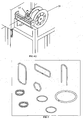
- the flux coating composition 2 of the claimed invention may also be used to coat forms other than brazing wire, such as strip and other continuous forms and other shapes of brazing materials 1. Spooled or coiled flux coated brazing material 1 may be utilized on automatic wire or strip feed brazing operations. It may also be utilized on automatic forming equipment for manufacturing brazing rings, washers, shims or other brazing pre-forms such as those depicted in Figure 6 . Alternatively, the flux coating composition 2 may be applied after the use of such forming equipment.
- the flux coated brazing material 1 includes a solid wire core surrounded by a flux coating FIG. 1 to a coated ratio by weight of 5-20% coating.
- This and similarly shaped flux coated brazing materials 1 facilitate ease of brazing as the flux coated brazing material 1 can be formed into a plurality of desired shapes and sizes and may be easily positioned over or with a joint or surface to be brazed.
- the application of heat to the flux coating composition 2 causes the binder to decompose well before the melting point of the flux. This allows the flux to melt uninhibited just prior to the melting point of the solid metal core which improves alloy flow and minimizes oxides which form during the heating process.
- brazing may be accomplished with little or no residual ash, carbon or impurities. Additionally the pre-engineered flux coating composition provides for the proper amount of chemical flux within the matrix of the flux coating composition 2 to provide the required fluxing action without leaving behind unreacted glasses of the potassium fluoroborate compounds, yielding a cleaner finished brazed joint.
- Yet another embodiment of the invention is a method of manufacturing a continuous length coated brazing material 1, comprising the steps of providing a brazing material 1 form of continuous length, providing a flux coating composition 2, applying a coating of said flux coating composition 2 to a surface of said brazing material 1 form; and in-line drying the flux coated brazing material 1.
- the brazing material 1 is treated to have a surface enhancement before the flux coating composition 2 is applied.
- the flux coated brazing material 1 is spooled, coiled or wound after it is dried.
- a method of brazing at least two components comprising the steps of placing at least two components in close proximity to create a joint gap, providing a flux coating composition 2 as described herein, providing a brazing material 1, applying said flux coating composition 2 to said two components or to said brazing material 1, heating the coated components or coated brazing material 1 to a preselected brazing temperature, and bringing the components and brazing material 1 in close proximity so that the brazing material 1 becomes molten, wets the components and flows into the joint gap.
- Another embodiment provides a method of brazing at least two components with a continuous length or non-linear flux-coated brazing material 1, comprising the steps of providing at least two components in close proximity to create a joint gap, providing a continuous length or non-linear flux-coated brazing material 1 as discussed herein, heating the two components or flux-coated brazing material 1 to a preselected brazing temperature, and bringing the two components and flux-coated brazing material 1 in close proximity so that the flux coated brazing material 1 becomes molten, wets the two components and flows into the joint gap.
- a method for preparing a flux-coated brazing material 1 as shown in FIG. 9 comprising the steps of preparing a flux coating composition 2 comprising a flux component mixed with a binder from TABLE 1, a solvent from TABLE 2, and plasticizer from TABLE 3 in proportionate ratios to constitute proper performance of the coating, preparing a brazing material 1 having a surface enhancement, depositing the flux coating composition 2 onto the brazing material 1 surface in a pressurized and heated reservoir chamber, to create a coating ratio of between 5-20% flux by weight, and processing said flux coated brazing material 1 longitudinally through a tunnel drying oven consisting of both radiant and convection drying.
- the flux coating composition 2 comprises a clean burning binder which decomposes to carbon dioxide and water
- the brazing material 1 is a wire having a diameter of between approximately 0.005-0.200 inches (0.0125-5.0mm)
- the flux-coated brazing material 1 comprises approximately 80-95% metal and approximately 5-20% flux coating composition 2
- the brazing material 1 base metal is of various alloy compositions of Cu, Ag, P, Ni, Zn, Sn, Cd, Mn or any of the brazing fillers described in Table 4
- the flux coating composition 2 is applied in a uniform controlled coating thickness of flux to a tolerance of +/-0.001 of an inch (+/-0.025mm).
- the brazing material 1 form is a wire, strip, ring or preformed shapes
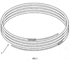
- flux coated brazing material 1 of continuous length may be formed into various form factors including wire loose coils, spools 16, preforms, rings, flat wire and strip. See FIG.
- the flux coating composition 2 has a clean burning constituent binder so that it is suitable for furnace and induction brazing and produces clean fluxing action leaving minimal flux residue, ash or carbon residue once consumed at temperatures ranging from 600°-1600°F (316-871 °C), and possibly for some brazing materials 1 as high as 1700°F (927°C) the dried flux coating composition 2 on said flux coated brazing material 1 is flexible, durable and does not readily crack, peel, chip, fracture or detach the surface of the brazing material 1. Further embodiments include the coating is durable enough to be fed through semi-auto or automatic braze alloy feed mechanisms.
- brazing material 1 any brazing material 1 or the metals or alloys or ceramics that may be joined thereby, of any flux composition. Any brazing flux or brazing material 1 may be used for the purposes of the invention.
- compositions having amounts higher than the lower limits are also expected to be effective for the purposes of the invention and so they are also encompassed within the claimed invention.
- TABLE 1 ELASTOMERS (BINDERS) Poly(propylene carbonate) Polyurethanes Poly(ethylene carbonate) Aromatic Polycarbonates Poly(alkylene carbonate) Cellulose Aliphatic Carbonates Poly Vinyl Chlorides Latex Compounds Silicates Polyesters TABLE 2: SOLVENTS Glycol Ether Acetates Esters Alcohols Glycols Polyols Ethers Alkanolamines Ethyleneamines Aromatic Solvents Aliphatic Naphthas Terpenes Water Ketones N-Methyl-2-pyrrolidone TABLE 3: PLASTICIZERS Citrates Sulfates Phosphates Phthalates Adipates Sebacate Esters Polyols Caster Oil
Landscapes
- Engineering & Computer Science (AREA)
- Mechanical Engineering (AREA)
- Chemical & Material Sciences (AREA)
- Inorganic Chemistry (AREA)
- Application Of Or Painting With Fluid Materials (AREA)
- Electric Connection Of Electric Components To Printed Circuits (AREA)
- Nonmetallic Welding Materials (AREA)
- Laminated Bodies (AREA)
Description
- This invention relates to a flux composition for use in brazing operations, a brazing material and, and a method of manufacturing said brazing material.
- Various methods are known for joining metal components, including mechanical bonding, adhesive bonding, soldering, welding and brazing. Although brazing, soldering and welding are similar, there are important differences. Soldering is generally performed at lower temperatures (below 450° Celsius), but does not produce as strong a joint. Welding is a high-temperature process in which the two metals to be joined are actually melted and fused together. Brazing is a method of joining two pieces of metal together with a third, molten filler material. Welded and brazed joints are usually at least as strong as the metals being joined. The welding process is preferable for applications which benefit from or require highly localized, pinpoint heating. Brazing is particularly useful in more difficult applications, such as joining of larger areas, linear joining, and joining metals or alloys having different melting points.
- In brazing the components to be joined are assembled so that there is a small gap, the so-called "joint gap" between their mating surfaces. The components are heated (or at least heated in the region of the proposed joint) to a temperature above the melting point of the brazing material but below the melting point of the components to be joined (or, in the case of two or more components are made of dissimilar metals or alloys, below the lower or lowest melting point of any of the components to be joined). Heat may be provided by torch, furnace, induction or any other heating method that may be used in joining components. During joining, the brazing material melts, wetting the surfaces of the components being joined, and is drawn or held in the joint gap by capillary action. Upon cooling, the brazing material solidifies, forming a metallurgical bond between the surfaces of the joined components.
- Brazing may be used to join metal-to-metal, alloy-to-alloy, metal-to-alloy, metal-to-ceramic, alloy-to-ceramic, or ceramic-to-ceramic. Ceramic components may be coated with metals or alloys prior to brazing. Brazing materials frequently melt at temperatures above 425° Celsius. Brazing materials may be comprised of one or more base metals, or eutectic mixtures or alloys thereof, such as aluminum, copper, gold, platinum, silver, tin, phosphorous, palladium, nickel, manganese, zinc, cadmium, chromium, boron, silicon, iron, carbon, sulphur, titanium, zirconium, tungsten, cobalt, molybdenum, niobium, selenium, lead, palladium, bismuth, beryllium, lithium and indium; other metals, metal alloys or minerals may also be used. A brazing material may be referred to as "brazing alloy," "brazing material," "brazing compound," "brazing metal," "brazing filler" or "filler metal." Throughout this application, any and all materials, elements, compounds or compositions used as brazing materials are referred to herein as "brazing material" or "brazing materials".
- It is well known in the art that it is necessary to prepare the surfaces of the components to be joined prior to applying the brazing material, so that the brazing material adheres to the surfaces to be joined. When components or surfaces are joined by brazing, it is preferable that both the brazing material and the joint area of the component surfaces are free from oxide films that may degrade the strength of the brazed joint. This may be done by carrying out the brazing operation in a reducing atmosphere, such as in a furnace. However, when brazing is done in air a flux composition or a flux compound (referred to as a "flux," "brazing flux" or "flux cover") is used to eliminate existing oxides or inhibit oxide films from forming on the brazing material and the surfaces of the components being joined. Thus, the flux must be capable of removing metal oxides at pre-selected brazing temperatures while remaining substantially inert with respect to the brazing material. Since fluxes are usually reactive (e.g., capable of removing oxides), the flux should be transformed to its molten state at or near the melting temperature of the brazing material. The flux is first applied to the surfaces of the components to be joined and is then activated to remove oxides and clean the surfaces by the application of heat at or around the joint.
- Although the principal purpose of the flux is to eliminate or inhibit the oxidation (formation of oxides) of the brazing material and of at least selected areas of the surfaces of the components being joined, the flux also must melt and flow at a temperature below the melting point of the brazing material, wet the surfaces of the components and brazing material, facilitate the wetting of the components by the molten brazing material, and be capable of being displaced by molten brazing material.
- Fluxes generally comprise a eutectic mixture of borates (including, without limitation, fluoroborates), fluorides (including, without limitation, bifluorides), chlorides, or salts thereof and one or more of the alkali metals, and are typically highly corrosive and hygroscopic in nature so that the flux adequately cleans the surfaces to be joined. Nonhygroscopic and noncorrosive flux compositions are known in the art. Known fluxes include those described in
U.S. Patents 6,395,223 ,6,277,210 ,5,781,846 and4,301,211 . Fluxes in the form of a liquid, solid, powder, slurry or paste may be applied to a brazing material or components to be joined. -
US 4,301,211 discloses a combination of brazing alloy and flux. The brazing material comprises a brazing alloy having a coating comprising a brazing flux and an elastomer. - Various methods are used to apply flux to the joint area and to the external surfaces of the components to be joined. Usually, the flux is applied to the surfaces to be brazed and the surfaces are heated to allow the flux to melt, flow and coat the surfaces. It is well known for the brazing flux in the form of a powder or paste to be applied to the joint area when the components are cold. The joint area is then heated until the brazing temperature is reached, and then the brazing material is applied. Various methods are used to apply brazing material to a joint, including, without limitation, insertion of the brazing material (in the form of a rod, wire, strip, disk, sheet, sheath or other form factor) into the entirety or a portion of the joint gap, upon which heat from the adjacent components begins to heat and thereby melt the brazing material. Alternatively, brazing material may be positioned at the mouth of the joint gap by melting the end portion of the brazing material.
- Linear brazing materials in the form of a "brazing rods" or "brazing wires" are well known in the art and include non-circular linear forms such as sheets or strips. A brazing rod is a fixed length brazing material generally of approximately 20 inches (50cm) or less. Linear brazing materials may be formed into circular or quasi-circular shape (e.g., oval, elliptical, hexagonal, semi-circular or "U"), loose coils, flat shapes (e.g., disks), corneals, saddles, bowls or other custom shapes. A brazing wire is a brazing material of continuous length. For purposes of this application, "continuous length" means a length greater than approximately twenty inches. Neither a bare brazing rod nor a bare brazing wire contain a flux core or flux coating.
- Due to the corrosive, hygroscopic nature of many fluxes and the residual or excess flux that results from various methods used to apply the flux, in many applications it is necessary or desirable to remove any residual flux or flux residue from the joined parts in order to prevent or limit corrosion of the joined components. The removal of residual flux increases the overall product cost due to the additional cleaning steps and the cost to dispose waste resulting from the cleaning process.
- Flux-coated brazing rods and flux-cored wires have been developed to eliminate the separate steps of applying the flux to the joint and removing and disposing of residual flux, thereby reducing the cost of manufacture. Flux-coated brazing materials have flux pre-applied to an exterior or exposed surface of the brazing material. Flux-cored brazing materials have flux pre-applied to on an interior surface, such as a channel, core, groove or other hollow form or cavity within a brazing material. Flux-coated and flux-cored brazing rods or wires may be made by first mixing a brazing flux composition, for example with water or an organic solvent or a liquid or semi-liquid binder to form a flux paste composition, a solid flux composition or a flux powder composition (such as by milling, crushing or pulverizing a solid flux). Binders commonly used include acrylic resins (e.g., 1-methoxy-2-propanol-acetate) and synthetic rubber compounds (e.g., butylpolybutadiene, polyisoprene, butadienestyrene and polyisobutylene). The flux paste may be applied to a brazing material using an extrusion press to extrude a concentric coating of the flux paste composition of a desired thickness onto the brazing rods and the coated rods are then baked to harden the flux coating.
- Alternatively the flux paste or powder may be deposited within a core, notch, groove, hole, crevice, cavity or other hollow area within a brazing material, to form a brazing material form, e.g. a flux-cored wire or sheath of brazing material, for example as described in
U.S. Pat. Nos. 5,781,846 and6,395,223 , owned by Omni Technologies Corporation. In flux-cored and flux-coated brazing materials, the surfaces of the components to be joined are heated and the flux-cored brazing material form is brought into contact with the heated surfaces, causing the flux to melt and flow and thereby causing the brazing material to melt and flow. - Continuous length flux-coated brazing materials are not currently known in the art. In many brazing applications, the brazing process is performed in a limited physical space and it is often necessary or desirable to bend, curl, angle or otherwise deform a linear brazing material (or to have a brazing material that is pre-formed in a bent or deformed shape) so that is may be appropriately positioned with respect to the joint gap and the components to be joined. A disadvantage of currently available flux-coated and flux-cored brazing rods or wires made in the above-described manner is that the fluxes are relatively brittle. Thus, when known flux-coated or flux-cored brazing materials are curled, bent or deformed (e.g., during transit, storage, handling or use) the flux coating or flux core easily cracks, fracture, peels or chips so that it becomes a non-continuous flux and portions of the flux coating or flux core may detach from the rods or wires. When the flux coating or flux core becomes detached and non-continuous, it loses its usefulness and effectiveness because it may produce a joint having less mechanical bond or strength.
- A further disadvantage of known flux-coated and flux-cored brazing materials is that the brittle flux-coating or flux-core does not allow the brazing material to be coiled, spooled, wound or manufactured into rings or other form factors that may be formed from the flux cored or coated wire or rod into a substantially circular, oval or elliptical shapes. When the brazing material is formed into a circular, oval or elliptical shape it causes the brittle flux coating or flux core to crack, peel, fracture (which permit moisture to enter the flux) and possibly detach from the brazing material. Thus, the length of the rod or wire is limited to shorter lengths (generally less than 20 inches [50cm]) and non-continuous forms that cannot be transported and handled in spooled, coiled, wound, rolled form or produced in other forms capable that permit the brazing material to be packaged, transported, stored or used in compact or compressed form.
- Another disadvantage is that current flux coating processes only lend themselves to coating brazing material, lengths less than or equal to approximately 20 inches (50cm), such as rods, due to the required post-cure step of baking the coating to cure or harden the flux--a step necessary to impart durability to the flux coating. The currently available form of flux coated brazing materials is limited to a rod of approximately 20 inches (50cm) or less, thus limiting the usefulness of the length and causing waste, as the last inch of the rod is generally discarded as being too small to effectively use.
- Accordingly, there is a need for a coated or cored brazing material that may be bent, curved, angled, curled, conformed or otherwise deformed in the brazing process. There is also a need for a continuously coated or cored brazing material of a continuous length that has a durable and flexible flux composition so that it may be spooled, coiled, wound, conformed, made or deformed into other circular or quasi-circular, non-linear or other form factors (e.g. rings, disks or ribbons). There also is a need for a durable, flexible flux composition that effectively prepares the surfaces to be joined, is clean burning and that may be deposited on the surface or core of a brazing material. Additionally, there is a need for a method of preparing a flux-coated or flux-cored brazing material that does not require post-cure heating or baking, so as to reduce manufacturing costs. There is also a need for a flux-coated or flux-cored brazing material that will provide for a wide selection of brazing base metal or alloy compositions and may include coated brazing materials having customized base metal properties. The claimed invention is directed to overcoming one or more of the problems set forth above.
- It is an object of the invention to provide a flux-coated brazing material that is easily utilized and able to conform to the contours of many joining surfaces. It is an alternative object of the claimed invention to provide a flux composition that, when applied as a coating to brazing materials, has sufficient elasticity to prevent, limit or minimize cracking, peeling, chipping, fracturing or detachment of the flux when the brazing material is bent or conformed to the contours of or to be positioned about a brazing joint.
- A further alternative object of the invention is to provide a flux composition that has suitable surface hardness when applied as a coating or core so as to provide durability during transit, handling, storage, use and disposal. It is a further alternative object of the invention to provide brazing material that has a durable and flexible flux core or flux coating and is of a continuous length. It is a further alternative object, not according to the claimed invention, to provide a process for coating or coring a semi-continuous length, continuous length, quasi-circular, nonlinear or other form or shape of brazing material whereby a post cure or baked hardening is not required. It is a further alternative object certain embodiments of the invention to provide a continuous length of flux-coated brazing material in a brazing process.
- Yet another alternative object, not according to the claimed invention, is to provide a process for surface preparation of brazing material to provide an interlock or enhanced binding surface for coating or coring a brazing material with a flux.
- A further alternative object, not according to the claimed invention, is to provide a flux composition suitable for continuous coating or coring of a substantially round, oval, elliptical cross-section form (such as a wire, tube or cable) or of substantially flat surfaces or cross-section (such as a strip, sheath or sheet).
- Another alternative object, not according to the claimed invention, is to provide a method of manufacturing a continuous length of flux-coated brazing material that may be wound, coiled or spooled. In alternate embodiments, the method includes spooling or coiling to facilitate automatic wire feed or manual brazing applications.
- Still another alternative object, not according to the claimed invention, is to provide a method of manufacturing a continuous length of flux-coated brazing material that may be fed into automatic, semi-automatic, or manual forming equipment to make flux-coated brazing rings, flux-coated washers, flux-coated shims or other flux-coated brazing pre-forms.
- Some embodiments may use a continuous length of flux-coated brazing material that is heated in torch, induction, furnace, or other common heating method used for joining metals.
- According to the claimed invention there is provided a flux composition for use in a brazing operation, the flux composition comprising: a solvent; a binder dissolved in the solvent; a flux powder or flux paste added to the polymer solution; and a plasticizer, wherein the flux composition comprises: between 30% by weight and 50% by weight non-hygroscopic flux; between 10% by weight and 30% by weight binder; between 30% by weight and 50% by weight solvent; and between 1 % by weight and 20% by weight plasticizer; and wherein the composition yields no metal oxides and no more than fifty parts per million of carbon, ash, fumes, smoke or other by-product contaminants when the composition is heated in a brazing operation.
- Preferred exemplary embodiments of the invention are illustrated in the accompanying drawings in which
-
Fig. 1 illustrates a partially formed flux-coated brazing material. -
Fig. 2 illustrates a brazing material having a surface micro-deformation. -
Fig. 3 illustrates a continuous length flux-coated brazing material. -
Fig. 4 illustrates the process of making the continuous length flux-coated brazing material. -
Fig. 5 illustrates various preformed, quasi-circular shapes made from the continuous length flux-coated brazing material. -
Fig. 6 illustrates various preformed shapes made from the continuous length flux-coated brazing material. -
Fig. 7 illustrates a flux-coated brazing material having a colored flux coating composition in various pigmented -
Fig. 8 illustrates a continuous length, dyed flux-coated brazing material. -
Fig. 9 is a flow chart describing the method of preparing a flux-coated brazing material of continuous length. - Applicants have discovered a flux composition suitable for coating or coring a brazing material 1 (when used as either a coating or a coring material the flux is referred to herein as a "flux coating composition") and that retains both sufficient hardness or toughness (durability) and sufficient flexibility (elasticity) so that the coated or cored
brazing material 1 may be bent, conformed, or deformed as needed to enhance the usefulness and effectiveness of the brazing. Theflux coating composition 2 of the claimed invention preferably utilizes a clean burning binder that yields a brazed joint substantially free of impurities or joint contamination. - Through extensive experimental investigation Applicants have discovered that a
flux coating composition 2 should preferably have at least one of the following characteristics or properties: - (a) The elastomer solution (e.g., the elastomer and any solvent used with the elastomer) when mixed with a flux powder or flux paste produces a composition paste which, upon pressure die coating onto a
brazing material 1, is capable of producing a smooth, dense, continuous coating or coring with sufficient green strength to permit the freshly coated or coredbrazing material 1 to be coiled, wound or spooled. Preferably, the elastomer has at least one of the properties described in Table 6 below. - (b) The elastomer is such that when freshly made the composition paste made from the flux powder or flux paste and the elastomer solution retains a workable consistency for a time sufficient to permit the
flux coating composition 2 to be applied; - (c) The elastomer and any other component of the
flux coating composition 2 that remains on thebrazing material 1 when they are ready for use does not interfere with the functioning of the brazing flux during the brazing process. Specifically, the elastomer and any other component remaining in theflux coating composition 2 should have good burn-off characteristics, that is, it or they would not produce excessive quantities of carbon, ash, fumes, smoke or by-product contaminants when a flux-coated or flux-coredbrazing material 1 is heated. Most preferably, it or they would burn off or volatilize substantially completely without leaving behind any material amount of solid residue (e.g., less than or equal to 50 ppm carbon, ash or other residue); - (d) The elastomer is such that the composition of flux powder or flux paste and elastomer will be capable of producing a
flux coating composition 2 which, after drying, is sufficiently hard so as to withstand handling without post-cure baking or hardening; - (e) The elastomer is such that the
flux coating composition 2 containing flux powder and elastomer would have the above desirable features (a) through (d) in addition to having a sufficiently high flux content to enable brazing operations to be effective. Most preferably the flux component should be more than 30 wt. % of theflux coating composition 2. - (f) The flux component of the
flux coating composition 2 is of a particle size distribution at least 140 mesh solids, preferably between approximately 200 and approximately 325 mesh solids, in order to facilitate homogenization and green strength of the dried coating. - (g) In addition to one of the other characteristics or properties listed above, the
flux coating composition 2 is capable of being colored with pigment or dye.FIG. 7 or8 . - The flux-coated brazing material 1 (i.e., the
brazing material 1 following application of the flux coating composition 2) preferably has at least one of the following characteristics or properties: - (h) A flexible and durable
flux coating composition 2 that does not crack, peel, fracture, chip, break or otherwise become non-continuous if thebrazing material 1 is bent, curved, conformed or otherwise deformed during normal packaging, shipping, handling, storage or use. - (i) An engineered flux coating composition thickness of between 0.0005 and 0.035 inches, preferably to +/-0.001 of an inch (0.00125 and 0.875mm preferably to +/-0.025mm), to provide optimal brazing performance.
- (j) An engineered flux coating composition thickness which yields low flux residue or low or no metal oxides upon completion of brazed joint.
- (k) Is clean burning leaving behind no carbon or ash deposits during or after completion of brazing.
- (1) An engineered coated product which can be made into wire, strip, preform, ring and other non-linear form factors.
- (m) A
brazing material 1 having a base metal or alloy composition of at least one of the elements of Table 4, preferably copper, silver, phosphorous, nickel, zinc, tin, cadmium, manganese. - (n) One or more of the properties described in Table 5 below.
- The preferred
flux coating composition 2 of the invention has properties (d) and (f) specified above and most preferably one or more or all of the remaining properties (a) to (c), (e) and (g). The preferred flux-coated or flux-coredbrazing material 1 of the invention has properties (h) and (1), and most preferably one or more of the remaining properties (i) through (n). - Applicants have discovered that one or more of the above properties (a) to (g) are possessed by such
flux coating compositions 2 having elastomers of relatively high molecular weight, such as aliphatic polycarbonates and possibly others of the compositions described in Table 1, and certain plasticizer compounds (including, without limitation, those plasticizers identified in Table 3). The addition of a plasticizer enhances the flexibility, adhesion, surface durability and toughness of theflux coating composition 2. For purposes of the invention, "high molecular weight" means a weight of greater than 50,000 daltons; preferably a high molecular weight is between approximately 150,000 and approximately 500,000 daltons. Typical of these polycarbonates are poly(alkylene carbonate), poly(propylene carbonate) and poly(ethylene carbonate). The Aliphatic Polycarbonates (in a suitable solvent) may be used on their own with a flux to make aflux coating composition 2. Alternatively, aliphatic polycarbonates, preferably poly(propylene carbonate) or poly(ethylene carbonate) or poly(alkylene carbonate) may be combined with one or more plasticizer compounds and a flux. Most preferably, the elastomer is the poly(alkylene carbonate) ofU.S. Patent 6,248,860 , A suitable solvent is DE Acetate although this is, of course, by no means the only solvent that maybe employed. Additional high molecular weight elastomers believed to be suitable for the invention are described in Table 1. Additional solvents believed to be suitable for the elastomer and/or flux are described in Table 2. Additional plasticizers believed to be suitable are described in Table 3. Other solvents or plasticizers may also be used as appropriate. - Although the
flux coating composition 2 may be made with any flux, the preferred flux is produced by formulation of a non-hydroscopic flux or non-corrosive flux, such as described inU.S. Pat. No. 6,395,223 owned by Omni Technology Corporation (e.g., potassium fluoroborate flux complex). Preferably, the flux is milled to a fine particle distribution of greater than or equal to approximately 200 mesh solids, preferably between 200 and 350 mesh solids. The flux is then mixed with an elastomer (also referred herein as a "binder"), and more preferably also with a plasticizer. Preferably, theflux coating composition 2 is formed as predetermined ratios with the following other ingredients:Non-Hygroscopic Flux 30-50% by weight a binder from TABLE 1 10-30% by weight a solvent from TABLE 2 30-50% by weight a plasticizer from TABLE 3 1 -20% by weight - The
flux coating composition 2 is then mixed to a concentration of approximately 60% by weight solids in preparation for coating application to the surface of thebrazing material 1. - An alternative embodiment of the
flux coating composition 2 suitable for a strong, durable hard coating with a suitable flexibility for spooling (e.g., wire, tube, cable, strip or sheet) is as follows: - 1-3% by weight plasticizer (preferably acetyl tributyl citrate);
- 18-22% by weight aliphatic polycarbonate (preferably poly(alkylene carbonate)) as previously discussed;
- 38-45% by weight solvent (preferably DE Acetate); and
- 28-35% by weight brazing flux powder (preferably the flux described in
U.S. Pat. No. 6,395,223 or6,277,210 ). - 3-5% by weight plasticizer (preferably acetyl tributyl citrate);
- 25-30% by weight aliphatic polycarbonate (preferably poly(alkylene carbonate) as in
U.S. Pat. No. 6,248,860 ) as previously discussed; - 32-40% by weight solvent (preferably DE Acetate); and
- 28-35% by weight brazing flux powder (preferably fluxes described in U.S. Pat. No.
-
6,395,223 or6,277,210 ). - For
flux coating composition 2 having a harder (more durable) coating, an aliphatic polycarbonate (preferably poly(propylene carbonate) or other elastomer, and most preferably poly(alkylene carbonate)), having a high molecular weight at the higher end of the "high molecular weight" range is preferable, most preferably in the range of between approximately 150,000 daltons and approximately 500,000 daltons, would be used with glass transition temperature greater than 40° C. - Any of the currently available wide range of
brazing materials 1 and brazing fluxes may be used for the purpose of this invention. However, the use of a non-hygroscopic, non-corrosive flux ofU.S. Pat. Nos. 6,395,223 and6,277,210 is preferred. - It should be noted that continuous coating of wire is common in the electrical and electronics industries where elastomers are used as insulators or to protect the wire core from corrosion or other environmental conditions. Elastomeric flux coatings known in the brazing arts must be subjected to post cure drying, heating or baking to harden the coating, and thus such coatings are currently only applied to brazing rods. The extra process of drying, baking or heating limits the
brazing materials 1 that may be coated to rods and shorter lengths because continuous-length product, while still having a tacky coating, could not be readily handled, stacked and stored during the post-cure drying or baking or heating process. - In contrast, the
flux coating composition 2 of the claimed invention, when applied tobrazing material 1 in accordance with the method taught herein, does not require post-cure air drying, heating or baking. Instead, the coating dries to sufficient hardness during the process of forming the flux-coatedbrazing material 1 according to the method described herein. - It should also be noted that, in conventional brazing operations carried under a flux cover, different fluxes are used depending on the composition and melting point of the
brazing material 1 and on the composition of the components to be joined. The same factors govern the composition of the flux used in the production of flux-coatedbrazing material 1 rods. Similarly, these factors also govern the composition of the flux and thebrazing materials 1 used in the claimed invention with respect to a particular brazing application. - An embodiment of the claimed invention comprises
flux coating composition 2 as applied to anybrazing material 1, and preferably brazingmaterials 1 of silver, copper, phosphorus, tin, zinc, nickel, cadmium, manganese, and alloys thereof. Such metals and alloys are well known in the art and are commercially available (for example, such alloys are currently sold under the trademark SILVALOY® by Wolverine Joining Technologies, LLC) coated with a mix containing a potassium borate/potassium fluoroborate flux as described inU.S. Patents 6,277,210 and6,395,223 (commercially available and sold under the registered trademark SILVACOTE™ available from Wolverine Joining Technologies, LLC). - In another embodiment of the invention,
brazing material 1 is prepared for coating or coring by treating or enhancing thebrazing material 1 surface in a manner to create an abrasion, scratch, perforation, scar or other defamation, preferably a microdefamation of between approximately 10 to 40 microinches (0.00001 to 0.00004 inches, 0.00025 to 0.001mm), to facilitate a mechanical bond between thebrazing material 1 surface and theflux coating composition 2. The mechanical bond functions to receive and secure the flux coating when it is applied to the surface of thebrazing material 1. For round wire, defamation may be performed utilizing a rotary straightener (e.g., such as that made by EMS, Bristol Conn.) and replacing the rotary inserts with a hard or hardened material capable of scratching, scaring or causing other abrasion to the surface of abrazing material 1, for example, without limitation, molded fibrous material or laminate having a heat-hardened binder (e.g., Micarta® [a registered trademark of International Paper Company], epoxy, epoxy glass, melamine and phenolic laminates), diamond, sapphire, carbon, steel or any other mineral, element, composition or material that is harder than thebrazing material 1 surface to be enhanced. This process functions to straighten the wire for coating in addition to scarifying the surface with a rotary surface enhancement that functions as a micro-lock to secure the flux coating. Flat surfaces may be prepared using MD Technology of Wolverine Tube, Inc., as described inU.S. Patent 5,775,187 . Alternatively, other methods of imparting a surface enhancement on abrazing material 1 include, without limitation, sand or grit blasting, wire brushing, roll forming, and die drawing. -
Figure 4A through Figure 4G illustrate the progressive process preferred by the inventors forcoating brazing material 1 with theflux coating composition 2 of the claimed invention. Thebrazing material 1 of the illustration inFig. 4A comprises a wire of brazing metal, such as a metal alloy, that has undergone a process to create microdeformation surface enhancement (3 inFigure 2 ). The brazing material 1 (brazing wire in this case) is fed through apressurized coating reservoir 10 filled with the prepared flux coating composition. Brazing wire enters the reservoir through anentrance guide 11 that can be such as capillary medical tubing or other tube orconduit 12 that is slightly larger than the diameter of the brazing wire. Once the brazing wire exits theentrance guide 11 it comes in contact with theflux coating composition 2 within the reservoir, and then exits through die orifice 13 (inFig. 4D ) that is of prescribed diameter larger than the wire to yield a specified coating thickness. To facilitate proper uniform application of theflux coating composition 2 and to accelerate drying, theflux coating composition 2 is heated to a temperature of between 25° and 150°C, preferably between approximately 150° and 220°F (65°- 105° C) and pressurized to between 5-40 pounds per square inch ("psi") (34.474 - 275.790 kiloPascals) at the coating reservoir prior to application. Coating thickness is regulated through anadjustable die orifice 13 as illustrated inFig 4D and through regulation of the applied pressure. Once the brazing wire exits the application reservoir, the coated brazing wire enters a dryingchamber 14Fig. 4E consisting of both radiant and convection tunnel drying. Drying may range between 100° and 300° Celsius, with optimal drying temperatures range from 250° - 400°F (120°-205° Celsius). Coated brazing wire is supported through the drying ovens under tension from acaterpillar belt drive 15 established at the end of the process lineFig. 4F such as a Witles Albert model NAK 100 transporter with Linatex material type belt, which regulates the speed of the coating and drying process. Coated brazing wire can then be directly level layer wound onto spools 16 (inFig. 4G ) utilizing equipment such as Hammond Engineering Spooler Machine with Amacoil/Uhing traversingwire guiding mechanism 17, or cut into discrete lengths or coiled to other loose coil form factors shown generally byreference numeral 4Fig. 3 . Theflux coating composition 2 of the claimed invention may also be used to coat forms other than brazing wire, such as strip and other continuous forms and other shapes ofbrazing materials 1. Spooled or coiled flux coatedbrazing material 1 may be utilized on automatic wire or strip feed brazing operations. It may also be utilized on automatic forming equipment for manufacturing brazing rings, washers, shims or other brazing pre-forms such as those depicted inFigure 6 . Alternatively, theflux coating composition 2 may be applied after the use of such forming equipment. - As illustrated for wire, the flux coated
brazing material 1 includes a solid wire core surrounded by a flux coatingFIG. 1 to a coated ratio by weight of 5-20% coating. This and similarly shaped flux coatedbrazing materials 1 facilitate ease of brazing as the flux coatedbrazing material 1 can be formed into a plurality of desired shapes and sizes and may be easily positioned over or with a joint or surface to be brazed. The application of heat to theflux coating composition 2 causes the binder to decompose well before the melting point of the flux. This allows the flux to melt uninhibited just prior to the melting point of the solid metal core which improves alloy flow and minimizes oxides which form during the heating process. Through use of a clean burning binder, brazing may be accomplished with little or no residual ash, carbon or impurities. Additionally the pre-engineered flux coating composition provides for the proper amount of chemical flux within the matrix of theflux coating composition 2 to provide the required fluxing action without leaving behind unreacted glasses of the potassium fluoroborate compounds, yielding a cleaner finished brazed joint. - Yet another embodiment of the invention is a method of manufacturing a continuous length coated
brazing material 1, comprising the steps of providing abrazing material 1 form of continuous length, providing aflux coating composition 2, applying a coating of saidflux coating composition 2 to a surface of saidbrazing material 1 form; and in-line drying the flux coatedbrazing material 1. In alternate embodiments, thebrazing material 1 is treated to have a surface enhancement before theflux coating composition 2 is applied. In yet another embodiment of the method, the flux coatedbrazing material 1 is spooled, coiled or wound after it is dried. - In another embodiment of the invention, there is provided a method of brazing at least two components, comprising the steps of placing at least two components in close proximity to create a joint gap, providing a
flux coating composition 2 as described herein, providing abrazing material 1, applying saidflux coating composition 2 to said two components or to saidbrazing material 1, heating the coated components orcoated brazing material 1 to a preselected brazing temperature, and bringing the components andbrazing material 1 in close proximity so that thebrazing material 1 becomes molten, wets the components and flows into the joint gap. - Another embodiment provides a method of brazing at least two components with a continuous length or non-linear flux-coated
brazing material 1, comprising the steps of providing at least two components in close proximity to create a joint gap, providing a continuous length or non-linear flux-coatedbrazing material 1 as discussed herein, heating the two components or flux-coatedbrazing material 1 to a preselected brazing temperature, and bringing the two components and flux-coatedbrazing material 1 in close proximity so that the flux coatedbrazing material 1 becomes molten, wets the two components and flows into the joint gap. - A method is also provided for preparing a flux-coated
brazing material 1 as shown inFIG. 9 comprising the steps of preparing aflux coating composition 2 comprising a flux component mixed with a binder from TABLE 1, a solvent from TABLE 2, and plasticizer from TABLE 3 in proportionate ratios to constitute proper performance of the coating, preparing abrazing material 1 having a surface enhancement, depositing theflux coating composition 2 onto thebrazing material 1 surface in a pressurized and heated reservoir chamber, to create a coating ratio of between 5-20% flux by weight, and processing said flux coatedbrazing material 1 longitudinally through a tunnel drying oven consisting of both radiant and convection drying. - In alternate embodiments, the
flux coating composition 2 comprises a clean burning binder which decomposes to carbon dioxide and water, thebrazing material 1 is a wire having a diameter of between approximately 0.005-0.200 inches (0.0125-5.0mm), the flux-coatedbrazing material 1 comprises approximately 80-95% metal and approximately 5-20%flux coating composition 2, thebrazing material 1 base metal is of various alloy compositions of Cu, Ag, P, Ni, Zn, Sn, Cd, Mn or any of the brazing fillers described in Table 4, and theflux coating composition 2 is applied in a uniform controlled coating thickness of flux to a tolerance of +/-0.001 of an inch (+/-0.025mm). - In further embodiments of the method: the brazing
material 1 form is a wire, strip, ring or preformed shapes; flux coatedbrazing material 1 of continuous length may be formed into various form factors including wire loose coils, spools 16, preforms, rings, flat wire and strip. SeeFIG. 5 In yet other embodiments: theflux coating composition 2 has a clean burning constituent binder so that it is suitable for furnace and induction brazing and produces clean fluxing action leaving minimal flux residue, ash or carbon residue once consumed at temperatures ranging from 600°-1600°F (316-871 °C), and possibly for somebrazing materials 1 as high as 1700°F (927°C) the driedflux coating composition 2 on said flux coatedbrazing material 1 is flexible, durable and does not readily crack, peel, chip, fracture or detach the surface of thebrazing material 1. Further embodiments include the coating is durable enough to be fed through semi-auto or automatic braze alloy feed mechanisms. - The invention described herein is not limited in any manner by the descriptions, definitions or characteristics of any
brazing material 1 or the metals or alloys or ceramics that may be joined thereby, of any flux composition. Any brazing flux orbrazing material 1 may be used for the purposes of the invention. - While the above compositions have been provided, deviations or modifications may be used. Again, the formulations of the
flux coating compositions 2 described above simply define a lower limit; therefore, compositions having amounts higher than the lower limits are also expected to be effective for the purposes of the invention and so they are also encompassed within the claimed invention. - The various tables referenced herein are set forth below:
TABLE 1: ELASTOMERS (BINDERS) Poly(propylene carbonate) Polyurethanes Poly(ethylene carbonate) Aromatic Polycarbonates Poly(alkylene carbonate) Cellulose Aliphatic Carbonates Poly Vinyl Chlorides Latex Compounds Silicates Polyesters TABLE 2: SOLVENTS Glycol Ether Acetates Esters Alcohols Glycols Polyols Ethers Alkanolamines Ethyleneamines Aromatic Solvents Aliphatic Naphthas Terpenes Water Ketones N-Methyl-2-pyrrolidone TABLE 3: PLASTICIZERS Citrates Sulfates Phosphates Phthalates Adipates Sebacate Esters Polyols Caster Oil -
- Headings represent the component base metal composition. Metals listed below a heading represent the brazing metals and alloys thereof that may be used to join the components. All identified metals may be used as the base metal or in combinations to form alloys.
- TABLE 5: PROPERTIES OF FLUX-COATED CONTINUOUS LENGTH BRAZING MATERIALS
- Flux is present in an amount of ≥ 5 % by weight.
- Withstands mechanical pressure of up to 220 psi (1517KPa) at between approximately 20° to 25° C without detaching from the brazing material.
- Bending Radius Range: 0.375 inches (9.5mm) to 1 inch (25.4mm) without the surface cracking (specific bending radius depends on particular
flux coating composition 2 formulation). - May be formed into preform rings, loose coils, wound around a spool.
- Coating bums back ("burn-back") when heat is removed: ≤ 0.125 inches (3.175mm) (solid metal).
- Absorbs ≤ approximately 1% water (by weight) at between 20-25° C.
- Compatible with all color pigment or dye additives.
- TABLE 6: PREFERRED ELASTOMER (BINDER) PROPERTIES
- Molecular weight: 10,000-1,000,000 daltons (more preferably 150,000 to 500,000)
- Glass Transition Temperature (Tg): 40°-300°F
- Tensile Strength (psi between 20°-25° C): 500-600 (3447 - 4137 KPa)
- Water Absorption (between 20°-25° C): ≤ 5%
- Decomposition Temperature: 100°-300° C
- Comprises at least 5% (by weight) of flux coating composition.
COPPER FILLER METALS: Cu, Ag, Zn, Sn, Fe, Mn, P, Pb, Al, Si
GOLD FILLER METALS: Au, Cu, Pd, Ni
ALUMINUM & MAGNESIUM FILLER METALS: Si, Cu, Mg, Bi, Fe, Zn, Mn, Cr, Ni, Ti, Be, Al
SILVER FILLER METALS: Ag, Cu, Zn, Cd, Ni, Sn, Li, Mn
FILLER METALS FOR VACUUM SERVICE: Ag, Au, Cu, Ni,Co, Sn, Pd; ,In
Claims (19)
- A flux composition for use in a brazing operation, the flux composition comprising:a solvent;a binder dissolved in the solvent;a flux powder or flux paste added to the polymer solution; anda plasticizer,
wherein the flux composition comprises:between 30% by weight and 50% by weight non-hygroscopic flux;between 10% by weight and 30% by weight binder;between 30% by weight and 50% by weight solvent; andbetween 1% by weight and 20% by weight plasticizer; andwherein the composition yields no metal oxides and no more than fifty parts per million of carbon, ash, fumes, smoke or other by-product contaminants when the composition is heated in a brazing operation. - A flux composition as claimed in claim 1 wherein the flux composition is mixed to 60% by weight solids.
- A flux composition as claimed in any preceding claim wherein the binder decomposes to carbon dioxide and water when it is heated in a brazing operation.
- A flux composition as claimed in any preceding claim, wherein the flux composition, after drying, is sufficiently hard so as to withstand handling without post-cure baking or hardening.
- A flux composition as claimed in any preceding claim, wherein the flux absorbs less than or equal to 1 % by weight water at temperatures between 20 and 25 degrees Celsius.
- A flux composition operation as claimed in any preceding claim, wherein the plasticizer is selected from the group consisting essentially of: citrates, phosphates, adipates, polyols, sulfates, phthalates, sebacate esters, and caster oil.
- A flux composition operation as claimed in any preceding claim, wherein the solvent is selected from the group consisting essentially of: glycol ether acetates, alcohols, polyols, alkanolamines, aromatic solvents, terpenes, ketones, N-mehtyl-2-pyrrolidone, esters, glycols, ethers, ethyleneamines, aliphatic naphthas, and water.
- A flux composition operation as claimed in any preceding claim, wherein the binder is an aliphatic polycarbonate is selected from the group consisting essentially of:poly(propylene carbonate), poly(ethylene carbonate), and poly(alkylene carbonate).
- A flux composition as claimed in any of claims 1 to 7 comprising a potassium fluoroborate flux complex mixed with:a binder selected from the group consisting essentially of: poly(propylene carbonate), poly(ethylene carbonate), poly(alkylene carbonate), aliphatic carbonates, poly vinyl chlorides, latex compounds, silicates, polyesters, polyurethanes, aromatic polycarbonates, cellulose;a solvent selected from the group consisting essentially of: glycol ether acetates, alcohol, polyols, alkanolamines, aromatic solvents, terpenes, ketones, N-methyl-2-pyrrolidone, esters ,glycols, ethers, ethyleneamines, aliphatic naphthasm water; anda plasticizer selected from the group consisting essentially of: citrates, phosphates, adipates, polyols, sulfates, phthalates, sebacate esters, caster oil.
- A flux composition as claimed in any preceding claim, wherein the flux composition comprises a pigment or dye.
- A brazing material for use in a brazing operation comprising:an elongate body of a metallic material;a flux composition as claimed in any of claims 1 to 10.
- A brazing material as claimed in claim 11, having at least one of the following features:wherein the brazing material has a longest dimension that is greater than approximately 20 inches (0.508 metres); andwherein the composition has a thickness of between 0.0005 inches (0.0127 millimetres) and 0.035 inches (0.889 millimetres).
- A brazing material as claimed in claim 11 or 12, wherein the flux composition is provided on the exterior surface of the metallic material or wherein the flux composition is provided in the core of the metallic material
- A brazing material as claimed in any of claims 11 to 13, wherein the brazing material is coiled.
- A brazing material as claimed in claim 14, wherein the flux composition does not crack, peel, fracture, chip, break, or otherwise become non-continuous when a coated brazing material is bent curved, conformed, or otherwise deformed during normal packaging, shipping, handling, storage or use.
- A brazing material as claimed in any of claims 11 to 15, wherein comprising 5-20% by weight flux composition.
- A brazing material as claimed in any of claims 11 to 16, wherein the metallic material is an alloy composition comprising two or more of copper, silver, phosphorus, nickel, zinc, tin, cadmium and manganese or a brazing filler selected from the group consisting essentially of:when the base metal comprises nickel and/or cobalt: nickel, chromium, boron, silicon, iron, carbon, phosphorous, sulfur, aluminium, titanium, manganese, copper, zirconium, tungsten, cobalt, molybdenum, niobium, and selenium;when the base metal comprises copper: copper, silver, zinc, selenium, iron, manganese, phosphorous, lead, aluminium, and silicon;when the base metal comprises gold: silver, copper, lead, and nickel;when the base metal comprises aluminium and magnesium: silicon, and copper, magnesium, bismuth, iron, zinc manganese, chromium, nickel, titanium, beryllium, and aluminium;when the base metal comprises silver: silver, copper, zinc, cadmium, nickel, tin, lithium and manganese; andfor vacuum service: silver, gold, copper, nickel, cobalt, tin, lead and indium.
- A method of manufacturing a brazing material as claimed in any of claims 11 to 17, the method comprising the steps of:a. providing an elongate body of metallic material;b. providing a flux composition as claimed in any of claims 1 to 12;c. applying said flux composition to a surface of said brazing material; andd. drying said flux composition,
wherein the step of drying said flux composition comprises passing the brazing material through a heated tunnel while in a state of tension. - A method of manufacturing a brazing material as claimed in claim 18, wherein the step of applying the flux composition comprises at least one of the following features:treating the surface of the metallic material to improve adhesion of the flux composition; andpassing the surface through a reservoir containing the flux composition at a temperature of between 25 and 150 degrees Celsius and under pressure of between 0.0345 and 0.276 megapascals.
Priority Applications (1)
| Application Number | Priority Date | Filing Date | Title |
|---|---|---|---|
| PL06837365T PL1945397T3 (en) | 2005-11-10 | 2006-11-09 | Brazing material with continuous length layer of elastomer containing a flux |
Applications Claiming Priority (2)
| Application Number | Priority Date | Filing Date | Title |
|---|---|---|---|
| US73532305P | 2005-11-10 | 2005-11-10 | |
| PCT/US2006/043856 WO2007058969A2 (en) | 2005-11-10 | 2006-11-09 | Brazing material with continuous length layer of elastomer containing a flux |
Publications (3)
| Publication Number | Publication Date |
|---|---|
| EP1945397A2 EP1945397A2 (en) | 2008-07-23 |
| EP1945397A4 EP1945397A4 (en) | 2012-07-25 |
| EP1945397B1 true EP1945397B1 (en) | 2016-03-02 |
Family
ID=38049173
Family Applications (1)
| Application Number | Title | Priority Date | Filing Date |
|---|---|---|---|
| EP06837365.3A Active EP1945397B1 (en) | 2005-11-10 | 2006-11-09 | Brazing material with continuous length layer of elastomer containing a flux |
Country Status (11)
| Country | Link |
|---|---|
| US (4) | US20070251602A1 (en) |
| EP (1) | EP1945397B1 (en) |
| JP (1) | JP2009515703A (en) |
| KR (2) | KR101414467B1 (en) |
| CN (2) | CN102848092A (en) |
| AU (1) | AU2006315655A1 (en) |
| BR (1) | BRPI0618466A2 (en) |
| CA (1) | CA2629176C (en) |
| MX (1) | MX2008006132A (en) |
| PL (1) | PL1945397T3 (en) |
| WO (1) | WO2007058969A2 (en) |
Families Citing this family (42)
| Publication number | Priority date | Publication date | Assignee | Title |
|---|---|---|---|---|
| US20070210037A1 (en) * | 2006-02-24 | 2007-09-13 | Toshifumi Ishida | Cooling block forming electrode |
| CN101489713B (en) | 2006-05-25 | 2012-11-28 | 贝尔曼-梅尔科发展有限责任公司 | Metal wire for brazing or soldering operations and method for its preparation |
| US8274014B2 (en) * | 2006-05-25 | 2012-09-25 | Bellman-Melcor Development, Llc | Filler metal with flux for brazing and soldering and method of making and using same |
| US8507833B2 (en) | 2006-12-11 | 2013-08-13 | Lucas-Milhaupt, Inc. | System and method of brazing using non-silver metals |
| US8116432B2 (en) * | 2007-04-20 | 2012-02-14 | General Electric Company | X-ray tube target brazed emission layer |
| US20090200363A1 (en) * | 2008-02-13 | 2009-08-13 | Trane International Inc. | Braze Ring |
| US9056367B2 (en) * | 2008-10-28 | 2015-06-16 | Elco Enterprises, Inc. | Conduit |
| US8354615B2 (en) * | 2009-03-05 | 2013-01-15 | Lincoln Global, Inc. | Manual welding electrode |
| US8127827B2 (en) * | 2009-04-23 | 2012-03-06 | Dunn Edmund M | Process and apparatus for direct chill casting |
| EP2493652A4 (en) | 2009-10-26 | 2017-02-08 | Lucas-Milhaupt, Inc. | Low silver, low nickel brazing material |
| CA2687926A1 (en) | 2009-11-25 | 2011-05-25 | Lucas Milhaupt, Inc. | Brazing material |
| US8535454B2 (en) * | 2010-11-23 | 2013-09-17 | Promerus, Llc | Polymer composition for microelectronic assembly |
| US8186564B1 (en) * | 2011-01-07 | 2012-05-29 | Exedy America Corporation | Brazing preform manufacture |
| US9352419B2 (en) * | 2011-01-13 | 2016-05-31 | Siemens Energy, Inc. | Laser re-melt repair of superalloys using flux |
| DE102011100608B4 (en) * | 2011-03-03 | 2024-03-28 | OSRAM Opto Semiconductors Gesellschaft mit beschränkter Haftung | Suspension for protecting a semiconductor material and method for producing a semiconductor body |
| US10987763B2 (en) * | 2011-09-23 | 2021-04-27 | Lucas-Milhaupt, Inc. | Luminescent braze preforms |
| WO2013044229A1 (en) * | 2011-09-23 | 2013-03-28 | Lucas Milhaupt, Inc. | Luminescent braze preforms |
| US9272350B2 (en) * | 2012-03-30 | 2016-03-01 | Siemens Energy, Inc. | Method for resistance braze repair |
| FR2988633B1 (en) * | 2012-03-30 | 2014-11-21 | Faurecia Interieur Ind | METHOD FOR ASSEMBLING A FIRST AND A SECOND PART, ESPECIALLY PARTS OF A MOTOR VEHICLE, BY INDUCTION BRAZING |
| US8740041B2 (en) * | 2012-07-03 | 2014-06-03 | Flux Brazing Schweiss-Und Lotstoffe Usa, Llc | Extruded brazing ring with integrated flux |
| US9821414B2 (en) * | 2013-01-31 | 2017-11-21 | Siemens Energy, Inc. | Welding electrode |
| CN105032727A (en) * | 2013-05-30 | 2015-11-11 | 卢卡斯米尔霍特公司 | Process for flux coating braze preforms and discrete parts |
| US9731383B2 (en) | 2014-07-09 | 2017-08-15 | Bellman-Melcor Development, Llc | Filler metal with flux for brazing and soldering and method of using same |
| CA2968332C (en) * | 2014-12-22 | 2019-06-04 | Halliburton Energy Services, Inc. | Chemically strengthened bond between thermally stable polycrystalline hard materials and braze material |
| RU2686160C1 (en) * | 2015-06-08 | 2019-04-24 | Сименс Энерджи, Инк. | Welding electrode |
| WO2017018155A1 (en) * | 2015-07-27 | 2017-02-02 | 住友金属鉱山株式会社 | Coated solder wire and method for manufacturing same |
| JP6471676B2 (en) * | 2015-07-27 | 2019-02-20 | 住友金属鉱山株式会社 | Coated solder wire and manufacturing method thereof |
| US10744601B2 (en) | 2015-08-07 | 2020-08-18 | Bellman-Melcor Development, Llc | Bonded brazing ring system and method for adhering a brazing ring to a tube |
| CN105217374B (en) * | 2015-09-14 | 2018-02-16 | 三江学院 | A kind of solder stick automatic winding cuts liftout attachment |
| JP6437419B2 (en) * | 2015-11-11 | 2018-12-12 | 日鐵住金溶接工業株式会社 | Flux-cored wire for carbon dioxide shielded arc welding |
| JP2017094360A (en) | 2015-11-25 | 2017-06-01 | 日鐵住金溶接工業株式会社 | Flux-cored wire for shield-arc welding using argon-carbon dioxide gas mixture |
| US20170157715A1 (en) * | 2015-12-02 | 2017-06-08 | Bellman-Melcor Development, Llc | Brazing Ring with Spikes and Method for Securing a Brazing Ring to a Tube |
| CN105436747B (en) * | 2015-12-03 | 2018-04-17 | 哈焊所华通(常州)焊业股份有限公司 | A kind of aluminium welding wire technology for plating titanium |
| PL3226258T3 (en) * | 2016-04-01 | 2019-04-30 | Gebauer & Griller Metallwerk Gmbh | Insulated electrical conductor |
| CN105921909A (en) * | 2016-07-18 | 2016-09-07 | 浙江亚通焊材有限公司 | Binder used for preparing high-temperature adhesive tape solders and high-temperature adhesive tape solders |
| DE102016116265A1 (en) | 2016-08-31 | 2018-03-01 | Faurecia Emissions Control Technologies, Germany Gmbh | Solder based on copper and use of the solder material |
| US11229969B2 (en) | 2017-09-21 | 2022-01-25 | Saf-Holland, Inc. | Brazed fifth wheel hitch assembly components and method of constructing same |
| CN108188615B (en) * | 2017-12-29 | 2020-08-28 | 郑州机械研究所有限公司 | Impact-resistant self-fluxing composite solder cake with spiral framework and preparation method thereof |
| CN108296669B (en) * | 2017-12-29 | 2020-08-28 | 郑州机械研究所有限公司 | Impact-resistant composite brazing filler metal cake with spiral framework and preparation method thereof |
| WO2019191609A1 (en) | 2018-03-30 | 2019-10-03 | Hobart Brothers Company | Tubular wires made from copper coated strip |
| WO2020223394A1 (en) * | 2019-04-30 | 2020-11-05 | Indium Corporation | Solder preform with internal flux core including thermochromic indicator |
| KR102522081B1 (en) * | 2021-05-28 | 2023-04-18 | 한국생산기술연구원 | continuous wire manufacturing device |
Family Cites Families (133)
| Publication number | Priority date | Publication date | Assignee | Title |
|---|---|---|---|---|
| US400869A (en) * | 1889-04-02 | hodgson | ||
| US607504A (en) | 1898-07-19 | David crowther | ||
| US1529748A (en) * | 1924-07-19 | 1925-03-17 | Nelda M Hilker | Vanity case |
| US1650905A (en) * | 1925-12-21 | 1927-11-29 | Oscar L Mills | Welding rod |
| US1629748A (en) | 1926-01-28 | 1927-05-24 | Stoody Co | Method of making welding rods and the resulting product |
| US1865169A (en) * | 1927-07-27 | 1932-06-28 | Westinghouse Electric & Mfg Co | Welding electrode |
| US1968618A (en) * | 1932-01-05 | 1934-07-31 | Joseph E Padgett | Driving axle |
| US2005189A (en) | 1933-07-10 | 1935-06-18 | Albert H Herr | Solder coupling |
| US2055276A (en) | 1934-07-03 | 1936-09-22 | Ici Ltd | Pipe joint or coupling |
| US2279284A (en) * | 1941-03-22 | 1942-04-07 | Wassermann Rene | Silver alloy |
| US2442087A (en) * | 1945-03-02 | 1948-05-25 | Mills Alloys Inc | Welding rod |
| US2499641A (en) * | 1945-12-22 | 1950-03-07 | Monroe Sherman | Brazing and hard soldering flux |
| US2465503A (en) * | 1947-10-08 | 1949-03-29 | Lincoln Electric Co | Welding electrode |
| US2565477A (en) | 1948-04-10 | 1951-08-28 | Dynoflow Solder Corp | Fluxed solder rod |
| GB692710A (en) | 1950-04-12 | 1953-06-10 | Thessco Ind Res Ltd | Improvements in or relating to self-fluxing solders |
| US2785285A (en) * | 1953-03-18 | 1957-03-12 | Nat Cylinder Gas Co | Composite welding electrode |
| US2958941A (en) * | 1954-02-17 | 1960-11-08 | Air Reduction | Flux-filled brazing rod and method of brazing with same |
| US3051822A (en) * | 1955-03-23 | 1962-08-28 | Chemetron Corp | Welding with blanket and gas arc-shield |
| US2927043A (en) | 1957-02-20 | 1960-03-01 | Solar Aircraft Co | Aluminum coating processes and compositions |
| US3033713A (en) | 1960-04-20 | 1962-05-08 | Air Reduction | Improved-stabilized brazing fluxes and binders |
| US3077131A (en) * | 1961-08-03 | 1963-02-12 | Pittsburgh Steel Co | Die rolling apparatus for knurling wire |
| NL298923A (en) * | 1962-10-12 | |||
| BE640425A (en) * | 1962-12-07 | |||
| US3198560A (en) | 1963-03-06 | 1965-08-03 | Parker Hannifin Corp | Brazed tube coupling |
| DE1298967B (en) | 1964-11-10 | 1969-07-10 | Guenther Dr | Method for filling recesses in the surface of soldering wires with flux |
| US3239125A (en) | 1963-12-20 | 1966-03-08 | Raychem Corp | Solder ring |
| US3290772A (en) | 1964-02-05 | 1966-12-13 | Gen Electric | Method of making a brazed joint |
| US3365565A (en) * | 1964-07-20 | 1968-01-23 | Hobert Brothers Company | Welding electrodes |
| CH466006A (en) * | 1964-09-07 | 1968-11-30 | Elek Ska Svetsningsaktiebolage | Process for the production of a tubular welding wire or welding rod enclosing a core |
| US3318729A (en) * | 1965-08-05 | 1967-05-09 | Du Pont | Tubular welding rod having a chlorine or fluorine substituted ethylenically unsaturated aliphatic hydrocarbon polymer core |
| US3688967A (en) * | 1966-05-09 | 1972-09-05 | Kobe Steel Ltd | Solid composite backing structure for single welding |
| GB1180735A (en) | 1966-05-27 | 1970-02-11 | Johnson Matthey Co Ltd | Improved Brazing Ring |
| CH483290A (en) * | 1966-11-23 | 1969-12-31 | Oerlikon Buehrle Elektroden | Filled welding wire |
| JPS516096B1 (en) * | 1967-01-23 | 1976-02-25 | ||
| US3542998A (en) * | 1967-06-07 | 1970-11-24 | Air Reduction | Cored electrode for welding in air |
| US3620830A (en) * | 1968-01-17 | 1971-11-16 | Lincoln Electric Co | Automatic arc welding electrode with an electrically conductive flux coating |
| US3534390A (en) * | 1968-04-29 | 1970-10-13 | Stoody Co | Welding wire |
| US3619429A (en) * | 1969-06-04 | 1971-11-09 | Yawata Welding Electrode Co | Method for the uniform extrusion coating of welding flux compositions |
| US3620869A (en) * | 1969-07-16 | 1971-11-16 | Clevepak Corp | Method of making tubes |
| US4121750A (en) | 1969-12-15 | 1978-10-24 | Vereinigte Aluminium-Werke Aktiengesellschaft | Processes for soldering aluminum-containing workpieces |
| US3695795A (en) | 1970-03-20 | 1972-10-03 | Conn Eng Assoc Corp | Production of powdered metal |
| US3610663A (en) | 1970-04-20 | 1971-10-05 | Aesoquip Corp | Brazed connection |
| US3642998A (en) * | 1970-04-22 | 1972-02-15 | Frederick A Jennings | Corrosion-inhibiting toolbox |
| US3703254A (en) | 1970-05-07 | 1972-11-21 | Ncr Co | Pre-fluxed solder powder |
| US3639721A (en) | 1970-11-13 | 1972-02-01 | Aeroquip Corp | Method of installing brazing rings |
| US3745644A (en) | 1971-07-28 | 1973-07-17 | Carrier Corp | Method for attaching solder rings to work pieces |
| US3980859A (en) | 1974-05-23 | 1976-09-14 | Huntington Alloys, Inc. | Cored wire junction |
| US4041274A (en) * | 1974-07-11 | 1977-08-09 | The International Nickel Company, Inc. | Maraging stainless steel welding electrode |
| US3967036A (en) * | 1974-07-11 | 1976-06-29 | The International Nickel Company, Inc. | Flux-coated arc welding electrode |
| US3935414A (en) * | 1974-10-11 | 1976-01-27 | Unicore, Inc. | Automatic fixed position pipe welding |
| GB1481140A (en) | 1975-05-23 | 1977-07-27 | Inst Elektroswarki Patona | Consumable wire |
| JPS5214511A (en) * | 1975-07-25 | 1977-02-03 | Hitachi Cable Ltd | Process for producing a linear additive |
| DE2719357A1 (en) * | 1977-04-30 | 1978-11-09 | Kjellberg Esab Gmbh | METHOD OF MANUFACTURING FILLER WIRE AND FILLER WIRE ELECTRODES |
| NZ188341A (en) * | 1977-09-16 | 1980-05-08 | Johnson Matthey Co Ltd | Brazing composition:brazing alloy and thermoplastic materi |
| US4174962A (en) * | 1978-04-27 | 1979-11-20 | Caterpillar Tractor Co. | Filled tubular article for controlled insertion into molten metal |
| GB2027617B (en) | 1978-08-01 | 1982-07-07 | Johnson Matthey Co Ltd | Flux coated brazing materials |
| US4214145A (en) * | 1979-01-25 | 1980-07-22 | Stoody Company | Mild steel, flux-cored electrode for arc welding |
| US4900895A (en) * | 1980-05-09 | 1990-02-13 | Alloy Rods Global, Inc. | Rectangular electrode |
| JPS5768296A (en) * | 1980-10-16 | 1982-04-26 | Nissan Motor Co Ltd | Automatic welding wire for surface hardening and overlaying |
| US4447472A (en) * | 1982-09-23 | 1984-05-08 | Essex Group, Inc. | Magnet wire coating method and article |
| US4430122A (en) * | 1982-09-29 | 1984-02-07 | Eutectic Corporation | Flux-cored arc welding tubular electrode |
| FR2541937B1 (en) * | 1983-03-03 | 1985-09-13 | Vallourec | COMPOSITE PRODUCT HAVING AN AGGREGATED TUBULAR METAL ENVELOPE AND A PULVERULENT CORE SUITABLE FOR WINDING |
| SE8304658L (en) * | 1983-08-29 | 1985-03-01 | Werner Adolf Holmgren | PROCEDURE AND DEVICE FOR CONTINUOUS MANUFACTURING OF POWDER FILLED WELD ELECTRODE |
| US4497849A (en) * | 1983-09-26 | 1985-02-05 | Hughes Howard C | Process for polymer coating electrical conductors |
| JPS60250893A (en) | 1984-05-25 | 1985-12-11 | Sumitomo Light Metal Ind Ltd | Aluminum alloy brazing filler metal for heat exchanger made of aluminum |
| US4587097A (en) * | 1984-06-22 | 1986-05-06 | Allied Corporation | Homogeneous low melting temperature brazing filler metal for joining ferrous and non-ferrous alloys |
| US4800131A (en) | 1984-12-20 | 1989-01-24 | Alloy Rods Global, Inc. | Cored wire filler metals and a method for their manufacture |
| US4762674A (en) | 1984-12-27 | 1988-08-09 | Westinghouse Electric Corp. | Brazing sleeve having ceramic flux band and method for applying same |
| US4571352A (en) * | 1985-01-16 | 1986-02-18 | Sanden Corporation | Method for coating aluminum metal body with aluminum alloy brazing filler metal |
| JPS61184395A (en) * | 1985-02-12 | 1986-08-18 | Sanden Corp | Corrosion preventive process for aluminum heat exchanger |
| US4624860A (en) * | 1985-10-15 | 1986-11-25 | Imperial Clevite Inc. | Method of applying a coating to a metal substrate using brazing material and flux |
| JPS62144894A (en) * | 1985-12-18 | 1987-06-29 | Asahi Chem Ind Co Ltd | Fire cracker curved welding rod |
| US5098010A (en) * | 1987-01-30 | 1992-03-24 | Carmichael Arthur O | Process using protective flux coatings for delaying joining and soldering operations |
| CA1303605C (en) | 1987-11-19 | 1992-06-16 | Stephen B. Unruh | Heat exchanger tube having embossed ring bell and brazing ring |
| US4901909A (en) | 1988-08-18 | 1990-02-20 | Fusion Incorporated | Flux and process for brazing aluminum material |
| US5219425A (en) * | 1989-08-25 | 1993-06-15 | Kabushiki Kaisha Kobe Seiko Sho | Flux containing wire for use in stainless steel welding |
| DE8910519U1 (en) | 1989-09-04 | 1989-10-12 | FONTARGEN GmbH, 6719 Eisenberg | Solder wire as hard solder |
| US4993054A (en) * | 1989-09-27 | 1991-02-12 | General Electric Company | Brazed X-ray tube anode assembly |
| US5228727A (en) | 1989-12-28 | 1993-07-20 | Showa Aluminum Corporation | Tubular body having pipe joint member attached thereto and method of producing same |
| AU636481B2 (en) * | 1990-05-18 | 1993-04-29 | Bracco International B.V. | Polymeric gas or air filled microballoons usable as suspensions in liquid carriers for ultrasonic echography |
| NO174455C (en) * | 1991-06-14 | 1994-05-11 | Norsk Hydro As | Method of joining aluminum components |
| US5175411A (en) | 1991-08-23 | 1992-12-29 | Westinghouse Electric Corp. | Method for welding structural gaps |
| US5184767A (en) | 1991-12-31 | 1993-02-09 | Compaq Computer Corporation | Non-wicking solder preform |
| JPH06190586A (en) * | 1992-12-25 | 1994-07-12 | Showa Alum Corp | Flux coated aluminum brazing filler metal |
| US5781846A (en) * | 1993-02-25 | 1998-07-14 | Jossick; James L. | Flux cored brazing composition |
| RU2044606C1 (en) | 1993-04-30 | 1995-09-27 | Николай Николаевич Зубков | Method of obtaining surfaces with alternative projections and hollows (variants) and tool for its realization |
| US5360158A (en) | 1993-07-15 | 1994-11-01 | The S.A. Day Mfg. Co., Inc. | Method for joining aluminum alloy tubes |
| US5418072A (en) * | 1993-09-20 | 1995-05-23 | Alcan International Limited | Totally consumable brazing encapsulate for use in joining aluminum surfaces |
| CA2127836A1 (en) * | 1994-03-18 | 1995-09-19 | Jian Ming Ni | Elongated flexible welding electrode |
| US5700573A (en) * | 1995-04-25 | 1997-12-23 | Mccullough; Francis Patrick | Flexible biregional carbonaceous fiber, articles made from biregional carbonaceous fibers, and method of manufacture |
| DE19537216A1 (en) * | 1995-10-06 | 1997-04-10 | Solvay Fluor & Derivate | Flux-coated metal components |
| US5749971A (en) * | 1996-03-28 | 1998-05-12 | Ni; Chong Yang | Apparatus for making a welding flux coating continously on a welding electrode |
| US5791005A (en) * | 1996-11-14 | 1998-08-11 | The Mill-Rose Company | Scarifying and deburring tool |
| US5806752A (en) | 1996-12-04 | 1998-09-15 | Ford Global Technologies, Inc. | Manufacture of aluminum assemblies by open-air flame brazing |
| JPH10249583A (en) * | 1997-03-05 | 1998-09-22 | Nippon Steel Weld Prod & Eng Co Ltd | Flux-cored wire for gas shielded arc welding |
| US5820939A (en) | 1997-03-31 | 1998-10-13 | Ford Global Technologies, Inc. | Method of thermally spraying metallic coatings using flux cored wire |
| NL1005765C2 (en) * | 1997-04-08 | 1998-10-09 | Koni Bv | Double acting damper with rod stroke volume compensation. |
| EP0991697A4 (en) * | 1997-06-30 | 2000-10-25 | Pac Polymers Inc | Functionalized poly(alkylene carbonate), and use thereof |
| US6426483B1 (en) | 1998-02-17 | 2002-07-30 | Lincoln Global, Inc. | Electrode and method of making same |
| TW464582B (en) * | 1998-02-17 | 2001-11-21 | Lincoln Global Inc | Welding wire and method of making same |
| JP3337416B2 (en) * | 1998-02-24 | 2002-10-21 | 株式会社デンソー | Aluminum extruded porous flat tube with excellent brazing properties for automotive heat exchangers and method for producing the same |
| CA2325455C (en) * | 1998-03-25 | 2011-05-17 | Solvay Fluor Und Derivate Gmbh | New fluxing agents |
| US6093761A (en) * | 1999-04-14 | 2000-07-25 | Stanton Advanced Materials, Inc. | Binder system and method for particulate material |
| US20020046627A1 (en) | 1998-06-10 | 2002-04-25 | Hitoshi Amita | Solder powder, flux, solder paste, soldering method, soldered circuit board, and soldered joint product |
| US6203628B1 (en) * | 1998-08-20 | 2001-03-20 | Toyo Aluminium Kabushiki Kaisha | Flux compositions for brazing aluminum, their films and brazing method |
| JP3747307B2 (en) * | 1998-10-15 | 2006-02-22 | 株式会社神戸製鋼所 | Water glass for welding material and method for producing the same |
| US6120848A (en) * | 1998-11-17 | 2000-09-19 | Ford Motor Company | Method of making a braze sheet |
| JP2002538006A (en) * | 1999-03-05 | 2002-11-12 | アルコア インコーポレイテッド | Method of depositing flux or flux and metal on metal brazing substrate |
| US6264062B1 (en) * | 1999-06-09 | 2001-07-24 | Craig D. Lack | Solder preforms with predisposed flux for plumbing applications |
| WO2001000366A1 (en) | 1999-06-25 | 2001-01-04 | Schuster Jerry L | Silver brazing flux and method of making |
| US6395223B1 (en) | 1999-06-25 | 2002-05-28 | Omn. Technologies Corporation | Method of making a flux, a brazing wire, and a brazing paste |
| PT1230065E (en) * | 1999-10-25 | 2004-02-27 | Solvay Fluor & Derivate | FUNDABLE FOR DRY APPLICATION |
| US6317913B1 (en) * | 1999-12-09 | 2001-11-20 | Alcoa Inc. | Method of depositing flux or flux and metal onto a metal brazing substrate |
| CA2328628A1 (en) * | 1999-12-21 | 2001-06-21 | Cecile J. Schoenheider | Moldable compositions |
| US6497770B2 (en) * | 2000-02-17 | 2002-12-24 | Toyo Aluminium Kabushiki Kaisha | Flux-containing compositions for brazing aluminum, films and brazing method thereby |
| KR100494015B1 (en) | 2000-03-31 | 2005-06-10 | 현대종합금속 주식회사 | Arc Welding Electrodes |
| US6376585B1 (en) * | 2000-06-26 | 2002-04-23 | Apex Advanced Technologies, Llc | Binder system and method for particulate material with debind rate control additive |
| JP3600786B2 (en) * | 2000-09-13 | 2004-12-15 | シャープ株式会社 | Thread solder, thread solder manufacturing equipment and joining parts |
| WO2002031023A1 (en) * | 2000-10-11 | 2002-04-18 | Pohang Iron & Steel Co., Ltd. | Copolymer comprising alkylene carbonate and method of preparing same |
| US6608286B2 (en) * | 2001-10-01 | 2003-08-19 | Qi Fen Jiang | Versatile continuous welding electrode for short circuit welding |
| WO2003034449A1 (en) * | 2001-10-12 | 2003-04-24 | Yazaki Corporation | Wire manufacturing method, wire manufacturing apparatus, and wire |
| WO2003068447A1 (en) | 2002-02-13 | 2003-08-21 | Honeywell International Inc. | Solder paste formulations, methods of production and uses thereof |
| EP1497068B8 (en) * | 2002-04-22 | 2013-12-25 | Alcoa Inc. | Flux coated brazing sheet |
| US6830632B1 (en) * | 2002-07-24 | 2004-12-14 | Lucas Milhaupt, Inc. | Flux cored preforms for brazing |
| US20040171721A1 (en) * | 2002-12-16 | 2004-09-02 | Esemplare Pascal E. | Stabilizing polyalkylene carbonate resins |
| WO2004061871A1 (en) | 2002-12-27 | 2004-07-22 | Yazaki Corporation | Electrical wire coating method |
| GB0308895D0 (en) | 2003-04-17 | 2003-05-21 | Johnson Matthey Plc | Coating compositions |
| JP2005032533A (en) * | 2003-07-11 | 2005-02-03 | Goto Denshi Kk | Forming device of varnish to electric wire, and forming method of varnish |
| US7267187B2 (en) | 2003-10-24 | 2007-09-11 | Smith International, Inc. | Braze alloy and method of use for drilling applications |
| US20050089440A1 (en) | 2003-10-24 | 2005-04-28 | Kembaiyan Kumar T. | Braze alloy |
| US7718719B2 (en) * | 2003-12-13 | 2010-05-18 | Pascal Esemplare | Method of stabilizing a normally solid polyalkylene carbonate resin against thermal and hydrolytic decomposition for at least producing tough coatings with excellent adhesion to both ferrous and non-ferrous metals |
| JP2006225718A (en) * | 2005-02-17 | 2006-08-31 | Kobe Steel Ltd | DEPOSITED METAL FOR HIGH STRENGTH Cr-Mo STEEL HAVING EXCELLENT LOW TEMPERATURE TOUGHNESS AND SR CRACK RESISTANCE |
| EP2106318A4 (en) * | 2007-01-04 | 2013-05-01 | Fry Metals Inc | FLOW FORMULATIONS |
-
2006
- 2006-11-09 KR KR1020087013946A patent/KR101414467B1/en not_active Expired - Fee Related
- 2006-11-09 CN CN2011104525804A patent/CN102848092A/en active Pending
- 2006-11-09 PL PL06837365T patent/PL1945397T3/en unknown
- 2006-11-09 KR KR1020137021581A patent/KR20130094867A/en not_active Ceased
- 2006-11-09 CN CNA2006800502603A patent/CN101500746A/en active Pending
- 2006-11-09 US US11/558,400 patent/US20070251602A1/en not_active Abandoned
- 2006-11-09 CA CA2629176A patent/CA2629176C/en active Active
- 2006-11-09 AU AU2006315655A patent/AU2006315655A1/en not_active Abandoned
- 2006-11-09 EP EP06837365.3A patent/EP1945397B1/en active Active
- 2006-11-09 BR BRPI0618466-9A patent/BRPI0618466A2/en not_active IP Right Cessation
- 2006-11-09 JP JP2008540225A patent/JP2009515703A/en active Pending
- 2006-11-09 MX MX2008006132A patent/MX2008006132A/en active IP Right Grant
- 2006-11-09 WO PCT/US2006/043856 patent/WO2007058969A2/en not_active Ceased
-
2008
- 2008-11-26 US US12/324,410 patent/US8753455B2/en active Active
-
2010
- 2010-12-08 US US12/963,051 patent/US20110073216A1/en not_active Abandoned
-
2014
- 2014-06-12 US US14/303,140 patent/US9656352B2/en not_active Expired - Fee Related
Also Published As
| Publication number | Publication date |
|---|---|
| PL1945397T3 (en) | 2016-08-31 |
| US20070251602A1 (en) | 2007-11-01 |
| BRPI0618466A2 (en) | 2011-08-30 |
| US9656352B2 (en) | 2017-05-23 |
| US8753455B2 (en) | 2014-06-17 |
| US20110073216A1 (en) | 2011-03-31 |
| KR20090117914A (en) | 2009-11-16 |
| AU2006315655A8 (en) | 2008-07-03 |
| WO2007058969A2 (en) | 2007-05-24 |
| US20140360628A1 (en) | 2014-12-11 |
| US20090101238A1 (en) | 2009-04-23 |
| AU2006315655A1 (en) | 2007-05-24 |
| EP1945397A2 (en) | 2008-07-23 |
| KR20130094867A (en) | 2013-08-26 |
| CN102848092A (en) | 2013-01-02 |
| EP1945397A4 (en) | 2012-07-25 |
| KR101414467B1 (en) | 2014-07-18 |
| CN101500746A (en) | 2009-08-05 |
| WO2007058969A3 (en) | 2007-12-21 |
| MX2008006132A (en) | 2008-10-23 |
| CA2629176A1 (en) | 2007-05-24 |
| JP2009515703A (en) | 2009-04-16 |
| CA2629176C (en) | 2013-01-08 |
Similar Documents
| Publication | Publication Date | Title |
|---|---|---|
| EP1945397B1 (en) | Brazing material with continuous length layer of elastomer containing a flux | |
| EP2583792B1 (en) | Saw wire | |
| JP5084076B2 (en) | Slag removal improvement welding wire | |
| JP2018199214A (en) | Abrasive article and method of forming | |
| KR20060015749A (en) | How to solder aluminum | |
| DE10000988A1 (en) | Method for producing a protective layer on the surface of a component or the like workpiece, solder material for this and their use | |
| EP1927420A3 (en) | Microwave brazing process | |
| US3033713A (en) | Improved-stabilized brazing fluxes and binders | |
| KR900000400B1 (en) | Homogeneous low melting copper base alloys, homogeneous brazing foils prepared therefrom, methods for their preparation, and metal bonding methods using the same | |
| JP3356843B2 (en) | Manufacturing method of aluminum material for brazing | |
| CN118204676A (en) | Lead-cadmium-free silver-based brazing material and preparation method thereof | |
| DE69123431T2 (en) | Partial elimination of copper deposits on a steel strip using mechanical means | |
| CN108044252A (en) | A kind of shock proof medicine core composite soldering cake of band spiral skeleton and preparation method thereof | |
| DE102006058376A1 (en) | Brazing foil comprises metal foil containing solder and with layer of adhesive on one or both sides | |
| CN115846936B (en) | A high-strength wear-resistant brazing filler metal and preparation method thereof, and a brazing method for a PDC drill bit | |
| CN1935443A (en) | Solid wire for gas shielded arc welding | |
| JPH0364443A (en) | Composite roll for rolling and its manufacturing method | |
| CN115255709A (en) | Preparation method of flux-cored solder ring with flux guiding function and flux-cored solder ring | |
| RU2351448C2 (en) | Composite solder alloy receiving | |
| CN108188615B (en) | Impact-resistant self-fluxing composite solder cake with spiral framework and preparation method thereof | |
| CN119098712A (en) | Core-wrapped silver-copper-zinc welding wire, production method and core-wrapped equipment | |
| EP1116547A2 (en) | Process for applying a protective coating to the surface of workpieces and brazing material used therefor | |
| JPH0535711B2 (en) | ||
| DE10064384A1 (en) | Workpiece with a cavity and a method for producing a wear-resistant coating therein | |
| KR20090049801A (en) | Metal wire saw for steel cutting and manufacturing method |
Legal Events
| Date | Code | Title | Description |
|---|---|---|---|
| PUAI | Public reference made under article 153(3) epc to a published international application that has entered the european phase |
Free format text: ORIGINAL CODE: 0009012 |
|
| 17P | Request for examination filed |
Effective date: 20080513 |
|
| AK | Designated contracting states |
Kind code of ref document: A2 Designated state(s): AT BE BG CH CY CZ DE DK EE ES FI FR GB GR HU IE IS IT LI LT LU LV MC NL PL PT RO SE SI SK TR |
|
| AX | Request for extension of the european patent |
Extension state: AL BA HR MK RS |
|
| REG | Reference to a national code |
Ref country code: HK Ref legal event code: DE Ref document number: 1121099 Country of ref document: HK |
|
| A4 | Supplementary search report drawn up and despatched |
Effective date: 20120622 |
|
| RIC1 | Information provided on ipc code assigned before grant |
Ipc: B23K 1/20 20060101AFI20120618BHEP Ipc: B23K 35/365 20060101ALI20120618BHEP |
|
| DAX | Request for extension of the european patent (deleted) | ||
| RAP1 | Party data changed (applicant data changed or rights of an application transferred) |
Owner name: OMNI TECHNOLOGIES CORPORATION Owner name: LUCAS-MILHAUPT WARWICK LLC |
|
| 17Q | First examination report despatched |
Effective date: 20131003 |
|
| REG | Reference to a national code |
Ref country code: DE Ref legal event code: R079 Ref document number: 602006048096 Country of ref document: DE Free format text: PREVIOUS MAIN CLASS: B23K0001200000 Ipc: B23K0035360000 |
|
| GRAP | Despatch of communication of intention to grant a patent |
Free format text: ORIGINAL CODE: EPIDOSNIGR1 |
|
| RIC1 | Information provided on ipc code assigned before grant |
Ipc: B23K 35/365 20060101ALI20141126BHEP Ipc: C08K 3/00 20060101ALI20141126BHEP Ipc: C08K 5/00 20060101ALI20141126BHEP Ipc: C08K 3/08 20060101ALI20141126BHEP Ipc: B23K 35/362 20060101ALI20141126BHEP Ipc: B23K 35/36 20060101AFI20141126BHEP |
|
| INTG | Intention to grant announced |
Effective date: 20141222 |
|
| REG | Reference to a national code |
Ref country code: HK Ref legal event code: WD Ref document number: 1121099 Country of ref document: HK |
|
| RAP1 | Party data changed (applicant data changed or rights of an application transferred) |
Owner name: LUCAS-MILHAUPT, INC. |
|
| GRAP | Despatch of communication of intention to grant a patent |
Free format text: ORIGINAL CODE: EPIDOSNIGR1 |
|
| INTG | Intention to grant announced |
Effective date: 20150817 |
|
| GRAS | Grant fee paid |
Free format text: ORIGINAL CODE: EPIDOSNIGR3 |
|
| GRAA | (expected) grant |
Free format text: ORIGINAL CODE: 0009210 |
|
| AK | Designated contracting states |
Kind code of ref document: B1 Designated state(s): AT BE BG CH CY CZ DE DK EE ES FI FR GB GR HU IE IS IT LI LT LU LV MC NL PL PT RO SE SI SK TR |
|
| REG | Reference to a national code |
Ref country code: GB Ref legal event code: FG4D |
|
| REG | Reference to a national code |
Ref country code: AT Ref legal event code: REF Ref document number: 777664 Country of ref document: AT Kind code of ref document: T Effective date: 20160315 Ref country code: CH Ref legal event code: EP |
|
| REG | Reference to a national code |
Ref country code: IE Ref legal event code: FG4D |
|
| REG | Reference to a national code |
Ref country code: DE Ref legal event code: R096 Ref document number: 602006048096 Country of ref document: DE |
|
| REG | Reference to a national code |
Ref country code: NL Ref legal event code: MP Effective date: 20160302 |
|
| REG | Reference to a national code |
Ref country code: LT Ref legal event code: MG4D |
|
| REG | Reference to a national code |
Ref country code: AT Ref legal event code: MK05 Ref document number: 777664 Country of ref document: AT Kind code of ref document: T Effective date: 20160302 |
|
| PG25 | Lapsed in a contracting state [announced via postgrant information from national office to epo] |
Ref country code: FI Free format text: LAPSE BECAUSE OF FAILURE TO SUBMIT A TRANSLATION OF THE DESCRIPTION OR TO PAY THE FEE WITHIN THE PRESCRIBED TIME-LIMIT Effective date: 20160302 Ref country code: ES Free format text: LAPSE BECAUSE OF FAILURE TO SUBMIT A TRANSLATION OF THE DESCRIPTION OR TO PAY THE FEE WITHIN THE PRESCRIBED TIME-LIMIT Effective date: 20160302 Ref country code: GR Free format text: LAPSE BECAUSE OF FAILURE TO SUBMIT A TRANSLATION OF THE DESCRIPTION OR TO PAY THE FEE WITHIN THE PRESCRIBED TIME-LIMIT Effective date: 20160603 |
|
| PG25 | Lapsed in a contracting state [announced via postgrant information from national office to epo] |
Ref country code: NL Free format text: LAPSE BECAUSE OF FAILURE TO SUBMIT A TRANSLATION OF THE DESCRIPTION OR TO PAY THE FEE WITHIN THE PRESCRIBED TIME-LIMIT Effective date: 20160302 Ref country code: LT Free format text: LAPSE BECAUSE OF FAILURE TO SUBMIT A TRANSLATION OF THE DESCRIPTION OR TO PAY THE FEE WITHIN THE PRESCRIBED TIME-LIMIT Effective date: 20160302 Ref country code: LV Free format text: LAPSE BECAUSE OF FAILURE TO SUBMIT A TRANSLATION OF THE DESCRIPTION OR TO PAY THE FEE WITHIN THE PRESCRIBED TIME-LIMIT Effective date: 20160302 Ref country code: AT Free format text: LAPSE BECAUSE OF FAILURE TO SUBMIT A TRANSLATION OF THE DESCRIPTION OR TO PAY THE FEE WITHIN THE PRESCRIBED TIME-LIMIT Effective date: 20160302 Ref country code: SE Free format text: LAPSE BECAUSE OF FAILURE TO SUBMIT A TRANSLATION OF THE DESCRIPTION OR TO PAY THE FEE WITHIN THE PRESCRIBED TIME-LIMIT Effective date: 20160302 |
|
| PG25 | Lapsed in a contracting state [announced via postgrant information from national office to epo] |
Ref country code: EE Free format text: LAPSE BECAUSE OF FAILURE TO SUBMIT A TRANSLATION OF THE DESCRIPTION OR TO PAY THE FEE WITHIN THE PRESCRIBED TIME-LIMIT Effective date: 20160302 Ref country code: IS Free format text: LAPSE BECAUSE OF FAILURE TO SUBMIT A TRANSLATION OF THE DESCRIPTION OR TO PAY THE FEE WITHIN THE PRESCRIBED TIME-LIMIT Effective date: 20160702 |
|
| REG | Reference to a national code |
Ref country code: FR Ref legal event code: PLFP Year of fee payment: 11 |
|
| PG25 | Lapsed in a contracting state [announced via postgrant information from national office to epo] |
Ref country code: CZ Free format text: LAPSE BECAUSE OF FAILURE TO SUBMIT A TRANSLATION OF THE DESCRIPTION OR TO PAY THE FEE WITHIN THE PRESCRIBED TIME-LIMIT Effective date: 20160302 Ref country code: PT Free format text: LAPSE BECAUSE OF FAILURE TO SUBMIT A TRANSLATION OF THE DESCRIPTION OR TO PAY THE FEE WITHIN THE PRESCRIBED TIME-LIMIT Effective date: 20160704 Ref country code: RO Free format text: LAPSE BECAUSE OF FAILURE TO SUBMIT A TRANSLATION OF THE DESCRIPTION OR TO PAY THE FEE WITHIN THE PRESCRIBED TIME-LIMIT Effective date: 20160302 Ref country code: SK Free format text: LAPSE BECAUSE OF FAILURE TO SUBMIT A TRANSLATION OF THE DESCRIPTION OR TO PAY THE FEE WITHIN THE PRESCRIBED TIME-LIMIT Effective date: 20160302 |
|
| REG | Reference to a national code |
Ref country code: DE Ref legal event code: R097 Ref document number: 602006048096 Country of ref document: DE |
|
| PG25 | Lapsed in a contracting state [announced via postgrant information from national office to epo] |
Ref country code: BE Free format text: LAPSE BECAUSE OF FAILURE TO SUBMIT A TRANSLATION OF THE DESCRIPTION OR TO PAY THE FEE WITHIN THE PRESCRIBED TIME-LIMIT Effective date: 20160302 Ref country code: IT Free format text: LAPSE BECAUSE OF FAILURE TO SUBMIT A TRANSLATION OF THE DESCRIPTION OR TO PAY THE FEE WITHIN THE PRESCRIBED TIME-LIMIT Effective date: 20160302 |
|
| PLBE | No opposition filed within time limit |
Free format text: ORIGINAL CODE: 0009261 |
|
| STAA | Information on the status of an ep patent application or granted ep patent |
Free format text: STATUS: NO OPPOSITION FILED WITHIN TIME LIMIT |
|
| PG25 | Lapsed in a contracting state [announced via postgrant information from national office to epo] |
Ref country code: DK Free format text: LAPSE BECAUSE OF FAILURE TO SUBMIT A TRANSLATION OF THE DESCRIPTION OR TO PAY THE FEE WITHIN THE PRESCRIBED TIME-LIMIT Effective date: 20160302 |
|
| 26N | No opposition filed |
Effective date: 20161205 |
|
| PG25 | Lapsed in a contracting state [announced via postgrant information from national office to epo] |
Ref country code: BG Free format text: LAPSE BECAUSE OF FAILURE TO SUBMIT A TRANSLATION OF THE DESCRIPTION OR TO PAY THE FEE WITHIN THE PRESCRIBED TIME-LIMIT Effective date: 20160602 Ref country code: SI Free format text: LAPSE BECAUSE OF FAILURE TO SUBMIT A TRANSLATION OF THE DESCRIPTION OR TO PAY THE FEE WITHIN THE PRESCRIBED TIME-LIMIT Effective date: 20160302 |
|
| REG | Reference to a national code |
Ref country code: CH Ref legal event code: PL |
|
| PG25 | Lapsed in a contracting state [announced via postgrant information from national office to epo] |
Ref country code: CH Free format text: LAPSE BECAUSE OF NON-PAYMENT OF DUE FEES Effective date: 20161130 Ref country code: LI Free format text: LAPSE BECAUSE OF NON-PAYMENT OF DUE FEES Effective date: 20161130 |
|
| REG | Reference to a national code |
Ref country code: IE Ref legal event code: MM4A |
|
| PG25 | Lapsed in a contracting state [announced via postgrant information from national office to epo] |
Ref country code: LU Free format text: LAPSE BECAUSE OF NON-PAYMENT OF DUE FEES Effective date: 20161130 |
|
| REG | Reference to a national code |
Ref country code: FR Ref legal event code: PLFP Year of fee payment: 12 |
|
| PG25 | Lapsed in a contracting state [announced via postgrant information from national office to epo] |
Ref country code: IE Free format text: LAPSE BECAUSE OF NON-PAYMENT OF DUE FEES Effective date: 20161109 |
|
| PG25 | Lapsed in a contracting state [announced via postgrant information from national office to epo] |
Ref country code: CY Free format text: LAPSE BECAUSE OF FAILURE TO SUBMIT A TRANSLATION OF THE DESCRIPTION OR TO PAY THE FEE WITHIN THE PRESCRIBED TIME-LIMIT Effective date: 20160302 Ref country code: HU Free format text: LAPSE BECAUSE OF FAILURE TO SUBMIT A TRANSLATION OF THE DESCRIPTION OR TO PAY THE FEE WITHIN THE PRESCRIBED TIME-LIMIT; INVALID AB INITIO Effective date: 20061109 |
|
| PG25 | Lapsed in a contracting state [announced via postgrant information from national office to epo] |
Ref country code: MC Free format text: LAPSE BECAUSE OF FAILURE TO SUBMIT A TRANSLATION OF THE DESCRIPTION OR TO PAY THE FEE WITHIN THE PRESCRIBED TIME-LIMIT Effective date: 20160302 |
|
| PGFP | Annual fee paid to national office [announced via postgrant information from national office to epo] |
Ref country code: TR Payment date: 20221101 Year of fee payment: 17 Ref country code: GB Payment date: 20221128 Year of fee payment: 17 Ref country code: FR Payment date: 20221123 Year of fee payment: 17 Ref country code: DE Payment date: 20221125 Year of fee payment: 17 |
|
| PGFP | Annual fee paid to national office [announced via postgrant information from national office to epo] |
Ref country code: PL Payment date: 20221102 Year of fee payment: 17 |
|
| REG | Reference to a national code |
Ref country code: DE Ref legal event code: R119 Ref document number: 602006048096 Country of ref document: DE |
|
| GBPC | Gb: european patent ceased through non-payment of renewal fee |
Effective date: 20231109 |
|
| PG25 | Lapsed in a contracting state [announced via postgrant information from national office to epo] |
Ref country code: DE Free format text: LAPSE BECAUSE OF NON-PAYMENT OF DUE FEES Effective date: 20240601 |
|
| PG25 | Lapsed in a contracting state [announced via postgrant information from national office to epo] |
Ref country code: GB Free format text: LAPSE BECAUSE OF NON-PAYMENT OF DUE FEES Effective date: 20231109 |
|
| PG25 | Lapsed in a contracting state [announced via postgrant information from national office to epo] |
Ref country code: FR Free format text: LAPSE BECAUSE OF NON-PAYMENT OF DUE FEES Effective date: 20231130 |
|
| PG25 | Lapsed in a contracting state [announced via postgrant information from national office to epo] |
Ref country code: GB Free format text: LAPSE BECAUSE OF NON-PAYMENT OF DUE FEES Effective date: 20231109 Ref country code: FR Free format text: LAPSE BECAUSE OF NON-PAYMENT OF DUE FEES Effective date: 20231130 Ref country code: DE Free format text: LAPSE BECAUSE OF NON-PAYMENT OF DUE FEES Effective date: 20240601 |
|
| PG25 | Lapsed in a contracting state [announced via postgrant information from national office to epo] |
Ref country code: PL Free format text: LAPSE BECAUSE OF NON-PAYMENT OF DUE FEES Effective date: 20231109 |