EP1945037B1 - Desosseuse - Google Patents
Desosseuse Download PDFInfo
- Publication number
- EP1945037B1 EP1945037B1 EP06824258A EP06824258A EP1945037B1 EP 1945037 B1 EP1945037 B1 EP 1945037B1 EP 06824258 A EP06824258 A EP 06824258A EP 06824258 A EP06824258 A EP 06824258A EP 1945037 B1 EP1945037 B1 EP 1945037B1
- Authority
- EP
- European Patent Office
- Prior art keywords
- leg
- meat
- holding means
- holder
- stripping
- Prior art date
- Legal status (The legal status is an assumption and is not a legal conclusion. Google has not performed a legal analysis and makes no representation as to the accuracy of the status listed.)
- Active
Links
- 235000013372 meat Nutrition 0.000 claims abstract description 85
- 210000000988 bone and bone Anatomy 0.000 claims abstract description 41
- 210000003423 ankle Anatomy 0.000 claims abstract description 26
- 244000144977 poultry Species 0.000 claims abstract description 9
- 210000002414 leg Anatomy 0.000 claims description 85
- 239000002775 capsule Substances 0.000 claims description 30
- 210000003127 knee Anatomy 0.000 claims description 30
- 210000000629 knee joint Anatomy 0.000 claims description 27
- 238000000034 method Methods 0.000 claims description 22
- 230000033001 locomotion Effects 0.000 claims description 20
- 230000006835 compression Effects 0.000 claims description 7
- 238000007906 compression Methods 0.000 claims description 7
- 230000005540 biological transmission Effects 0.000 claims description 5
- 210000000078 claw Anatomy 0.000 abstract description 45
- 210000001624 hip Anatomy 0.000 abstract 4
- 210000001981 hip bone Anatomy 0.000 abstract 2
- 210000001503 joint Anatomy 0.000 abstract 1
- 210000001930 leg bone Anatomy 0.000 abstract 1
- 241000287828 Gallus gallus Species 0.000 description 25
- 238000007790 scraping Methods 0.000 description 10
- 239000002184 metal Substances 0.000 description 7
- 210000002435 tendon Anatomy 0.000 description 5
- 210000001694 thigh bone Anatomy 0.000 description 4
- 210000003205 muscle Anatomy 0.000 description 3
- 230000004308 accommodation Effects 0.000 description 2
- 230000000295 complement effect Effects 0.000 description 2
- 210000002310 elbow joint Anatomy 0.000 description 2
- 230000000284 resting effect Effects 0.000 description 2
- 239000000725 suspension Substances 0.000 description 2
- 210000000689 upper leg Anatomy 0.000 description 2
- 241000286209 Phasianidae Species 0.000 description 1
- 238000005452 bending Methods 0.000 description 1
- 230000010006 flight Effects 0.000 description 1
- 235000012054 meals Nutrition 0.000 description 1
- 239000012528 membrane Substances 0.000 description 1
- 230000003340 mental effect Effects 0.000 description 1
- 210000004417 patella Anatomy 0.000 description 1
- 210000001519 tissue Anatomy 0.000 description 1
Images


Classifications
-
- A—HUMAN NECESSITIES
- A22—BUTCHERING; MEAT TREATMENT; PROCESSING POULTRY OR FISH
- A22C—PROCESSING MEAT, POULTRY, OR FISH
- A22C21/00—Processing poultry
-
- A—HUMAN NECESSITIES
- A22—BUTCHERING; MEAT TREATMENT; PROCESSING POULTRY OR FISH
- A22C—PROCESSING MEAT, POULTRY, OR FISH
- A22C21/00—Processing poultry
- A22C21/0023—Dividing poultry
- A22C21/003—Filleting poultry, i.e. extracting, cutting or shaping poultry fillets
-
- A—HUMAN NECESSITIES
- A22—BUTCHERING; MEAT TREATMENT; PROCESSING POULTRY OR FISH
- A22C—PROCESSING MEAT, POULTRY, OR FISH
- A22C17/00—Other devices for processing meat or bones
-
- A—HUMAN NECESSITIES
- A22—BUTCHERING; MEAT TREATMENT; PROCESSING POULTRY OR FISH
- A22C—PROCESSING MEAT, POULTRY, OR FISH
- A22C21/00—Processing poultry
- A22C21/0069—Deboning poultry or parts of poultry
- A22C21/0076—Deboning poultry legs and drumsticks
Definitions
- the invention relates to a device for filleting or deboning leg or wing parts of poultry, such as chicken or turkeys, according to the preamble of claim 1.
- a device for filleting or deboning leg or wing parts of poultry, such as chicken or turkeys according to the preamble of claim 1.
- Such device is known from US 5,277,649 .
- US 5,277,649 in the name of the applicant shows a deboner that is adapted for in a set-up deboning the chicken leg of both the thighbone and the drumstick.
- Said deboner comprises several deboning modules that move along a processing path.
- Each deboning module comprises a support block in which the end of the thighbone is secured, and stripping claws in which the end of the drumstick bone is secured.
- the bones are held in line with each other by a straight bar positioned along the processing path, which bar keeps the chicken legs in a stretched position at the level of the knee joint.
- the stripping claws move towards the support block, wherein the end of the drumstick bone is accommodated in a hollow cylinder blade that moves along, with which blade the meat mass will finally be cut loose against the support block.
- the drum stick bone may as a result end up beyond the hollow cylinder blade, and the thigh bone may break, as a result of which the deboning process can be disrupted.
- a further deboner for a chicken leg is known from EP 0.803.195 , and comprises a clamp for attaching the knee joint, and movable supports on both sides and spaced apart from the clamp for pushing the thigh bone and drum stick upward, as a result of which the knee joint is held in a stretched position.
- a movable cylinder blade pierces the positioned chicken bone around the bones, as a result of which the chicken leg is pushed out of the clamp and the supports that move away.
- An incorrect placement of the chicken leg in the clamp may result in the knee joint not remaining in the wanted stretched position, resulting in the cylinder blade cutting the chicken leg to pieces.
- the diameter of the cylinder blade is adapted to accommodation of the knee joint, as a result of which usable meat is left behind around the bones.
- US 4,669,150 discloses a method and an apparatus for boning meal of a chicken leg by meens of a belt-shaped cutter that moves between two jaw members shetching the chicken leg. It is an object of the invention to provide a device for filleting or deboning leg or wing parts of poultry, wherein the position of the leg or wing part, and particularly the parts that are engaged during deboning, can be maintained.
- the invention provides a device four filleting or deboning leg or wing parts of poultry according to claim 1 Because of the first holding means the end can be positioned for the filleting or deboning process, wherein due to the cooperation the positioning can be maintained during the process. Due to axial movement it is moreover possible to achieve a compact structure of the first holder.
- the first holding means are located in the cylinder blade they are able to continue guiding the end of the leg or wing part in the cylinder blade or even pull at it, as a result of which the cylinder blade is able to cut all round through the meat on the held bone.
- the leg or wing part can remain in the stretched position.
- the device comprise a holder assembly for the leg part to move the leg part along a processing path, and a blade positioned along the processing path, wherein the holder assembly comprises said first holder and a second holder for holding both ends of the leg part, wherein the first and second holder are adapted for rotation of the leg part about its bone axis when the leg part passes along the blade. Due to the rotation the muscles and tendons in the leg part can be cut loose all round for the filleting or deboning process.
- the holder assembly is adapted for step-wise rotation of the leg part about its bone axis when the leg part passes along the blade. Due to step-wise rotation the rotation steps can simply be effected using stops or flights along a processing path.
- the second holding means are movable with respect to the first holding means from an inactive position, in which the end of the leg or wing part can be placed in the first holder, and an active position, in which the end is confined in the first holder.
- the leg or wing part can be placed at the beginning or at the end of the process, after which during the process the position of the leg or wing part remains the same.
- the first holding means are adapted for permanently holding the end of the leg or wing part during the filleting or deboning process. Due to permanently holding the position of the end, and thus the entire leg or wing part can be maintained during the process.
- the second holding means may themselves serve as aid or processing part during the process when the cylinder blade of the second holding meens comprises a leading and with a cutting edge wherein the second holding means are adapted for with the cutting edge passing the first holding means in the direction of the leg or wing part.
- the leading end may act as cutting tool.
- the second holding means get an extra function in addition to cooperating with the first holding means in a retaining manner.
- the second holding means are adapted for remaining active after the cutting edge has passed past the first holding means.
- first and second holding means are adapted for in radial direction of the leg or wing part fittingly confining the end of the leg or wing part.
- the fitting confinement can further counteract the bending away of the held end in radial direction, and thus in the natural direction of the elbow or knee joint.
- first holding means comprise first gripper means for at least partially engaging about a narrowed portion behind a knuckle of the leg or wing part, and a placement opening for placing the leg or wing part in the first holding means and then bringing the narrowed portion in contact with the gripper means.
- the first gripper means comprise at least one curved first gripper member for fitting abutment against the narrowed portion behind the knuckle of the leg or wing part, as a result of which the end can already to a certain extent be placed stably in the first holder even before the second holding means have been activated.
- first gripper means comprise two opposite first gripper members, preferably in U-arrangement, for abutment against the narrowed portion behind the knuckle of the leg or wing part, wherein the first gripper members with opposite ends define a part of the placement opening of which the size is adapted to the size of the narrowed portion behind the knuckle.
- the first holding means comprise a first hollow cylinder, wherein the placement opening and the gripper means have been formed by a recess in the cylinder wall at an end of the hollow cylinder.
- the cylinder blade is positioned around the first hollow cylinder, preferably snugly fitting.
- Meat can be removed to the bone of the leg or wing part when the device comprises first stripping means that are adapted for engagement onto the meat behind the first holder and/or first holding means and then stripping the meat in a direction away from the first holder.
- the first holding means during the deboning process are kept at the same height in axial direction of the leg or wing part.
- the leg or wing parts can be placed, for instance manually, in the first holder with overview when the first holder and/or first holding means are adapted for keeping the leg or wing part in vertical position, preferably with the ankle knuckle upward.
- the device comprises second stripping means that are adapted for stripping meat in the direction of the first holder, wherein preferably the first and second stripping means are adapted for in between them compressing meat or bringing the meat under compression and then driving the meat from the bone parts at the level of the knee joint.
- first and second stripping means are adapted for in between them compressing meat or bringing the meat under compression and then driving the meat from the bone parts at the level of the knee joint.
- the device comprises a knee capsule cutter positioned along the processing path for cutting into the knee capsule after a stripping motion of the first and/or second stripping means.
- the knee capsule extends over the knee and partially consists of tendons.
- the knee capsule cutter may act supplementary to for instance the said cutting edge of the second holding means in order to ensure that the tendons are sufficiently cut through.
- the knee capsule cutter comprises a meat retainer and a blade, wherein the meat retainer is adapted for locally detaining stripped meat from the first and/or second stripping means for providing an access space for the blade between the first and/or second stripping means and the meat retainer.
- the meat retainer is able to shield the meat from the blade, so that the blade only cuts into the knee capsule without damaging the surrounding meat. Misplaced cuts in the surrounding meat are not wanted.
- the meat retainer comprises a first meat guiding surface with a pilot edge, which surface extends in transport direction and is inclined towards the bone axis, for movement of stripped meat with respect to the bone in a direction towards the knee joint.
- the meat guiding plate is able to retain meat that after stripping has moved back in the stripping direction, which can take place with little force as the meat has already been stripped off.
- Transfer of stripped meat from the stripping means to the first meat guiding surface can take place in a smooth motion when the first meat guiding surface is positioned for by means of the pilot edge finding support on a stripping surface of the first and/or second stripping means.
- the meat guiding surface may in that case yield with the stripping means when the meat guiding plate is hinged opposite the pilot edge to a stationary carrier of the meat retainer.
- the meat retainer comprises a second meat guiding surface extending substantially parallel to the transport direction, and positioned at a short distance from the blade for guiding the stripped meat around the blade.
- the second meat guiding surface extending parallel to the transport direction may shield the flat side of a blade, in the form of a circular blade, from colliding with the meat.
- the blade is positioned for movement over a stripping surface of the first and/or second stripping means at a short distance from or in contact with the stripping surface.
- the knee capsule cutter is positioned for cutting into the knee capsule from one bone side.
- the device comprises a circular blade suspended along a processing path of the device, wherein the circular blade is attached to a driven shaft that is positioned at fixed distance from and parallel to a drive shaft for the circular blade, wherein the drive shaft and the driven shaft are rotatably connected with a joint swivelling arm and are connected one to the other with a drive transmission, wherein friction in the drive transmission provides a positioning force for pressing the swivelling arm and thus the circular blade in the direction of the processing path.
- Additional compression or positioning means for the circular blade such as a compression spring, may be superfluous in this suspension.
- the invention furthermore provides a device for filleting or deboning leg or wing parts of poultry, comprising a holder for an end of a leg or wing part, wherein the holder comprises a plate in which a passage opening is situated for the end of the leg or wing part, wherein the passage opening is at least partially bowl-shaped.
- the bowl shape renders the holder suitable for at least partially accommodating a knee or elbow joint therein, as a result of which the leg part getting stuck or jammed in the passage at or after an axial movement in the direction of the holder can be counteracted.
- the size of the passage opening can be adapted, for instance by placing a knuckle through the passage opening, when the plate comprises a slot oriented radially towards the passage opening, wherein a closing piece is accommodated in the slot which closing piece is formed complementary to the plate and the passage opening, wherein the closing piece is movable in the slot with respect to the passage opening.
- the passage opening at the inside is at least partially bounded by a cutting or scraping edge, wherein the cutting or scraping edge preferably forms a portion of a separately placeable blade.
- the cutting or scraping edge may ensure a proper detachment of the meat from the bone, resulting in the meat looking undamaged. Cutting or scraping edges that have become blunt can simply be replaced by replacing the separately placeable blade. The other parts of the deboner can therefore be durably used.
- Inner edges of the passage opening can be used as stripper for meat when the smallest size of the passage opening is larger than the size of the bone parts between a knuckle and a knee joint, and is smaller than the size of the knee joint.
- Parts of for instance stripped meat can be separated from the bone parts when the device comprises a cylinder blade for cutting the meat loose all round from a bone of the leg or wing part, wherein the cylinder blade is positioned for coming into cutting contact with the plate.
- the diameter of the cylinder blade is larger than the largest diameter of the passage opening.
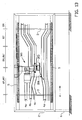
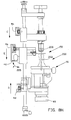
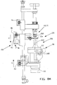
- the deboner 1 according to an embodiment of the invention as shown in figures 1A and 1B comprises a frame 2 placed on the legs 6, having at the upper side and lower side endless circulating chain conveyors 5 of which the chain wheels (not shown) are driven synchronously by means of vertical shafts 3.
- the deboner 1 comprises several deboning units 50 that have been attached to the chain conveyors 5 for transport according to a horizontal conveyor track in transport direction A.
- Figure 1A only shows one of the deboners 50.
- the conveyor track considered in transport direction A, consecutively comprises a placement section 81, a confinement or clamping section 82, a transverse cutting section 83, an engagement section 84, and at the opposite side a stripping section 85, an all round cutting section 86, a release section 87 and a return section 88.
- the placement section 81, the confinement or clamping section 82, the transverse cutting section 83, the engagement section 84, the stripping section 85 and the all round cutting section 86 extend at the same side of the machine, so that an operator is able to keep an overview of the various consecutive process steps.
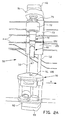
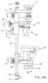
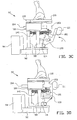
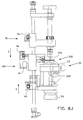
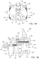
- the deboning unit 50 shown in figures 2A and 2B comprises two vertical guides 52 that have been attached to the chains, an upper support 51 fixedly connected to the guides 52, an ankle knuckle holder 60 at the upper support 51, an all round cutter 70, a stripper 150 and a hip knuckle holder 90.
- the hip knuckle holder 90 comprises a carriage 94 that is movable in vertical direction G along the guide bars 52 by an operating roller 95, a horizontal support 92 at the carriage 94, a metal base 98 with a vertical shaft 99 which is bearing mounted in the support 92 so as to be rotatable, and a rotary block 93 at the shaft 99 for rotation of the base in direction K (see figure 8F ).
- a synthetic support block 100 is attached on the base 98, the support block having parallel horizontal passages in which metal guides 104 of a synthetic slide block 103 have been slidably accommodated.
- a metal support plate 117 having a synthetic attachment plate 110 thereon is attached on the slide block 103, which synthetic attachment plate rests on a metal support plate 118 on the support block 100.
- the attachment plate 110 comprises a slot 121 extending in the slide direction Z for a complementary formed, elongated synthetic closing piece 109.
- the closing piece 109 is attached on an elongated elevation 119 of the support plate 118.
- lowerings 91 have been formed that together form a bowl-shaped recess, which in the centre merges into a through opening 108 in line with the shaft 99.
- the support plates 117, 118 have been provided with cutting or scraping edges 116, 167 which protrude to the inside at the bottom side of the lowerings 91.
- the curve path 4D for the operating roller 95 of the hip knuckle holder 90 preferably is fully adjustable as regards height in order to adjust the distance between the hip knuckle holder 90 and the ankle knuckle holder 60 that as regards height is fixed, for various lengths of chicken legs 200.
- the base 98 comprises a first hinge arm 120 which with a hinge 112 is connected to a second hinge arm 101 below the slide block 103.
- the first hinge arm 120 comprises an operating roller 111 spaced apart from the hinge 112.
- the slide block 103 is pre-biassed by means of draw springs 141 towards the support block 100.
- the hinge arms 101, 120 are stably in line with each other, resting against a stopper 114.
- the hinge arms 101, 120 buckle to the inside as shown in figure 3C , as a result of which the hip knuckle holder 90 forcefully enters the closing position as shown in figure 3D .
- the attachment plate 110 then fittingly accommodates the closing piece 109 more deeply into the slot 121 in direction Z.
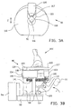
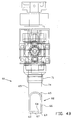
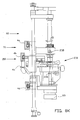
- the ankle knuckle holder 60 as shown in figures 4A and 4B comprises a hollow, vertically positioned mental tube 69 that is bearing mounted in the upper support 51 so as to be rotatable.
- a recess 62 has been formed in the wall.
- Said recess 62 contains an inclined portion 65 that merges into a straight portion 66 having a depth equalling half the diameter of the tube 69. Due to this recess 62 two horizontally extending attachment claws 63 have been formed (first holding means of first holder) at the lower side. Said attachment claws 63 have been provided with a bevelling 64 at the inside.
- the attachment claws 63 form a U-arrangement and at their ends keep a passage opening 67 free for passage of a narrowed portion behind the ankle knuckle of a chicken leg.
- the attachment claws 63 may alternatively form a C-arrangement.
- the height of the recess 62 is larger than the size of an ankle knuckle of a chicken leg.
- a rotary block 61 has been attached that corresponds with the rotary block 93 of the hip knuckle holder 90 for rotation of the tube 69 in direction B about a vertical axis.
- the round cutter 70 as shown in figures 4A and 4B comprises a carriage 73 which is slidable in vertical direction C about guides 52, an operating roller 79 for sliding the carriage 73, a support 72 at the carriage 73, and a cylinder blade 71 (second holding means of first holder) that is bearing mounted in the support 72 so as to be rotatable.
- the cylinder blade 71 is situated around the tube 69 of the ankle knuckle holder 60.
- the cylinder blade 71 has a circumferential, even cutting edge 74.
- the cutting edge 74 has been formed by sharpening the cylinder blade 71 inclined all round from the outside. Alternatively the cutting edge 74 can be sharpened all round from the inside.
- the diameter of the cylinder blade 71 exceeds the size of the upper edge of the bowl-shaped lowerings 91 in the attachment plate 110.
- the cylinder blade 71 comprises a toothed wheel 75 able to mesh with a gear rack (not shown) positioned stationary along the conveyor track, for rotation of the cylinder blade 71 in direction D about its vertical axis.
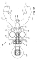
- the stripper 150 as shown in figures 5A and 5B comprises a carriage 151 which in vertical direction E is slidable along the guide bars 52, a first operating roller 159 for sliding the carriage 151, a support 152 at the carriage 151, and two plate-shaped stripping claws 154 which in a horizontal plane can be hinged about a common hinge 153 below the end of the support 152. Spaced from the common hinge 153 each stripping claw 154 comprises a hinge 155 for operating arms 156, wherein the operating arms 156 come together at a hinge point 140 of a central operating arm 157 horizontally movable along the support 152.
- Said operating arm 157 is movable in a horizontal direction by means of a movement mechanism 161 having a second operating roller 158, wherein an upward motion of the operating roller 158 in the direction F (see figure 2B ) leads to the stripping claws 154 moving towards each other from the opened position according to figure 5A to the closed position according to figure 5B .
- the ends of the stripping claws 154 have been shaped such that in closed position they come to lie one above the other with end plates 164 in order to counteract the stripping claws 154 moving vertically apart under the influence of vertical stripping forces. Behind the end plates 164 the stripping claws 154 comprise semicircular recesses 160 with finished inner edges.
- FIGS 6A and 6B show a part of the longitudinal cutter 130.
- the longitudinal cutter 130 comprises a horizontal beam 139 in which a total of four vertical drive shafts 134 have been bearing mounted.
- the drive shafts 134 at the upper side comprise a first pulley 137 that are in contact with a belt 138 for driving the drive shafts 134 in a same direction of rotation by means of an electromotor (not shown).
- At the bottom side the drive shafts 134 have been bearing mounted in a swivelling arm 132, wherein above the swivelling arm 132 a second pulley 135 is situated about the drive shaft 134.
- a second shaft is bearing mounted in the swivelling arm 132, which second shaft at the upper side is provided with a third pulley 133 and at the bottom side with a horizontally positioned circular blade 140.
- a synthetic belt 136 is situated around the second and third pulley 135, 133. Due to rotation of the drive shaft 134 in direction S, the circular blade 140 is rotated in the same direction S and simultaneously due to the friction of/in the belt 136 and/or the arrangement of bearings in the swivelling arm 134 is driven in the direction of the conveyor track.
- the driving force towards the conveyor track may also occur due to the mass inertia of the circular blade 140, for instance at accelerating (again) after having been decelerated as a result of cutting.
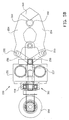
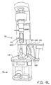
- the knee capsule cutter 300 as shown in figures 7A and 7B is intended to cut into or through knee capsule 210 that is situated over knee cap (not further shown) at the location of the knee joint 202.
- the knee capsule consists of several tendons which at the location of the thigh change into muscle tissue.
- the knee capsule cutter 300 comprises a mounting part 301 that is connected to a vertical U-profile 302, a horizontal support 303 at the end of the U-profile 302, a first elongated, plate-shaped lifting track 306 having a synthetic scraping edge 340, which is hinged to a second horizontally extending elongated plate-shaped lifting track 305, and two vertical bars 304 which at the bottom side have been connected to the second lifting track 305 and which at the upper side extend through the support 303. At the upper side the vertical bars 304 are connected by means of intermediate pieces 311 to a horizontal bar 309.
- a vertical bar 308 extends through the end of the horizontal bar 309. At the upper side the vertical bar 308 is provided with a stop 310 resting on the horizontal bar 309, and at the bottom side is connected by means of a hinge 307 to a first lifting track 305.
- the angle between the first and the second lifting track 306, 305 is adjustable by sliding the stop 310 along the vertical bar 308, as a result of which the position of the vertical bar 308 can be adjusted in direction W2.
- the stop 310 allows an upward motion of the end of the first lifting track 306 in direction X.
- the height of the first and second lifting track 306, 305 in vertical direction W1 is jointly adjustable by sliding the vertical bars 304, which by means of adjustment screws 330 have been locked within the horizontal support 303.
- the knee capsule cutter 300 has a horizontal circular blade 319 that is positioned under the second lifting track 305.
- the circular blade 319 is attached to a vertical shaft 320 that is bearing mounted in a swivelling arm 321.
- a vertical drive shaft 322 is bearing mounted, which by means of a transmission 326 is connected to an electromotor 324.
- the shafts 320, 322 have both been provided with a pulley 323, 325.
- a synthetic belt 136 is situated around the pulleys 323, 325.
- the circular blade 319 Due to rotation of the drive shaft 322 in direction U the circular blade 319 is rotated in the same direction U and simultaneously due to the friction of/in the belt 136 and/or the arrangement of bearings in the swivelling arm 321 is driven in the direction U towards the conveyor track.
- the cutting edge 318 of the circular blade 319 then protrudes in vertical projection from the second lifting track 305.
- the drive force towards the conveyor track may also arise due to the mass inertia of the circular blade 319, for instance at accelerating (again) after having been decelerated as a result of cutting.
- the process of deboning a chicken leg with the deboner 1 is shown in the figures 8A-8L .
- both the drum stick and the thigh of the chicken leg are deboned, that means the whole leg.
- the meat of this chicken leg is incised longitudinally down to the bone at the inside, as a result of which the meat acquires a more or less square contour after the process.
- the deboning unit 50 as shown in figure 8A at the start of the process moves in transport direction A along the placement section 81, in which the hip knuckle holder 90 is opened, the cylinder blade 71 is above the recess 62 in the tube 69, and the stripping claws 1 54 are in the opened position above the cutting edge 74 of the cylinder blade 71.
- the chicken leg 200 is now brought in an inclined position and oriented with the hip knuckle 205 diagonally downward and in direction N brought to the hip knuckle holder 90.
- the hip knuckle 205 is hooked in direction P behind the opening 108 in the attachment plate 110, after which the chicken leg 200 is erected in direction Q until in front of the attachment claws 63 of the ankle knuckle holder 60.
- the chicken leg 200 is pulled slightly upward in order to stretch the knee joint 202, so that the ankle knuckle 208 in direction R can be placed in the recess 62 as shown in figure 8C .
- the ankle knuckle 208 drops against the attachment claws 63 as shown in figure 8D .
- the knee joint 202 also remains stretched due to the form-closed confinement in the still opened attachment plate 110.
- the deboning unit 50 is suitable for both left and right legs.
- the knee capsule 210 is then located at the side of the knee joint 202 facing away from the guides 52.
- the deboning unit 50 subsequently moves along the clamping section 82.
- the cylinder blade 71 here moves downward over the tube 69, until the attachment claws 63 have been accommodated in the cylinder blade 71.
- the ankle knuckle 108 is confined behind the attachment claws 63 in the cylinder blade 71.
- the attachment plate 110 is moved towards the closing piece 109, as a result of which the hip knuckle 205 is confined under the attachment plates 110 and the closing piece 109.
- the hip knuckle holder 90 is moved several centimetres downward, as a result of which the knee joint 202 is stretched further.
- the deboning unit 50 moves along the circular blades 140.
- the circular blades 140 here rotate with the cutting edge in direction S counter the transport direction A.
- the circular blades 140 are positioned such that they cut through the tendons and muscles behind the ankle knuckle 208 down to the bone.
- the bone is only lightly touched by the cutting edge of the circular blades 140.
- the rotary blocks 61 and 93 are each time turned a quarter of a turn in the direction B and K by the stationary teeth 8 along the conveyor track, as a result of which each time more than a quarter of the cut around a bone is made.
- the deboning unit 50 runs through the engagement section 84, in which the stripping claws 154 in the opened position are moved downward in direction E until they are at the level of the longitudinal cut under the ankle knuckle 208 as shown in figure 8G . Subsequently the stripping claws 154 are closed in order to abut the bone with the finished edges 160.
- the stripping claws 154 move further down in direction E and the attachment plate 110 moves upward in direction G as shown in figure 8H .
- the cylinder blade 71 follows the stripping claws 154 in direction C at short distance. Due to the mutual movement of the stripping claws 154 and the attachment plate 110, the meat is stripped from the ankle knuckle 108 and the hip knuckle 205 towards the knee joint 202, wherein the hip knuckle 205 is accommodated more deeply into the hip knuckle holder 90 via opening 108, and the ankle knuckle 208 remains in confinement behind the attachment claws 63.
- the meat is then pressed against the attachment plate 110 by the stripping claws 154 and driven from the bones as shown in figure 8J .
- the stripping claws 154 open, after which the cylinder blade 71 passes in between until it is pressed forcefully against the attachment plate 110 and the closing piece 109 as shown in figure 8K .
- the knee joint 202 is then situated in the bowl-shaped lowerings 91 in the attachment plate 110 and the closing piece 109. Due to the tension in the meat when compressing, cutting all round with the cylinder blade 71 runs smoothly.
- the meat rotating along with the rotating cylinder blade 71 is prevented by the detaining forces of the stripping claws 154. Because the stripping claws 154 open when passing the cylinder blade 71, the meat placed under tension is pulled away from the path of the cylinder blade 71.
- the cylinder blade 71 is rotated in direction D during the round cutting section 86 due to engagement of the toothed wheel 75 onto a stationary gear rack (not further shown) along the conveyor track, as a result of which the last parts of the meat around the knee joint 202 are cut loose.
- FIG. 8L An elastic slider 180 positioned along the conveyor track subsequently wipes the meat from the hip knuckle holder 90, wherein the bones may pass through an opening 182 between the two upright elastic flaps 181 on the slider 180. Behind the slider 180 a stationary longitudinal bar (not shown) is positioned that presses the ankle knuckle in a direction counter the accommodation direction out of the ankle knuckle holder 60.
- Figures 8M-8Q show the operation of the deboner 1 in an alternative stripping section 85' and round cutting section 86', wherein the knee capsule cutter 300 is used.
- the alternative stripping section 85' starts after the stripping claws 154 have been closed as shown in figure 8G .
- the vertical movements of the round cutter 70, the stripper 150 and the hip knuckle holder 90 are then controlled by curve paths 4 that have been locally adapted for that purpose.
- the stripping claws 154 move further down in direction E and the attachment plate 110 moves upward in direction G as shown in figure 8M . Due to the mutual movement of the stripping claws 154 and the attachment plate 110, the meat is stripped from the ankle knuckle 108 and the hip knuckle 205 towards the knee joint 202, wherein the hip knuckle 205 is accommodated more deeply into the hip knuckle holder 90 via opening 108, and the ankle knuckle 208 remains in confinement behind the attachment claws 63. The meat is then pressed against the attachment plate 110 by the stripping claws 154 and driven from the bones as shown in figure 8N .
- the stripping claws 1 54 open at the end of the alternative stripping section 85' and they move back upward in the opened position in direction M, wherein the stripping claws 154 in height direction at approximately halfway the attachment plate 110 and the attachment claws 63 stand still as shown in figure 8P .
- the stripping claws 154 are then free from the meat.
- the hip knuckle holder 90 moves down again in direction L, as a result of which the knee joint 200 is held amply above the attachment plate 110 again by the ankle knuckle holder 60.
- the portion of the meat at the side of the knee capsule cutter 140 slides in direction V over the first lifting track 306, as a result of which this meat portion is held above the attachment plate 110 and the knee capsule 210 still connected to the bone becomes freely accessible in horizontal direction over the upper surface of the hip knuckle holder 90.
- the stripping claws 154 are closed shortly in order to retain the position of the ankle knuckle 208 in the ankle knuckle holder 60.
- the upward motion of the hip knuckle holder 90 in direction T continues until the attachment plate 110 with only slight vertical intermediate distance has arrived under the meeting circular blade 319 as shown in figure 8Q .
- the first lifting track 306 in this case has come to lie substantially horizontal in line with the second lifting track 305, and the knee joint 202 hangs above the upper surface of the attachment plate 110. Due to the motion of the deboning unit 50 in direction A the circular blade 319 shaves over the attachment plate 110 and cuts through the knee capsule 210 under the knee joint 202.
- the circular blade 319 during the contact with the bone, reciprocally moves while exerting a slight pressure force in direction U on the capsule 210 and the bone under the knee capsule 210.
- the cylinder blade 71 moves down in order for with the cutting edge 74 finally go past the stripping claws 154 that were shortly before that opened again.
- the cylinder blade 71 and the stripping claws 154 together move down in direction C and E, respectively, as a result of which the stripping claws 154 exert a detaining force on the meat and the cylinder blade 71 comes into contact with the attachment plate 110.
- the cylinder blade is rotated in direction D in order to cut the last parts of the meat around the knee joint 202 loose all round, after which the release section 87 as described above is run through.
- Figures 9A and 9B show an alternative hip knuckle holder 90' for the deboning unit 50. Corresponding parts have been provided with reference numbers with an accent.
- the metal base 98' of the alternative hip knuckle holder 90' is provided with two rollers 171 at the bottom side facing away from the carriage 94, which rollers in transport direction are positioned adjacent to each other.
- the rollers may roll against a support strip 163 extending in the transport direction A, which strip is stationarily attached to the frame 2, as a result of which it can be counteracted that the horizontal support 92 sags and bulges to the outside during the cylinder blade 71 exerting the cutting force on the attachment plate 110.
- the hip knuckle holder 90' comprises a guide 128 on the carriage 94' through which guide a pressure bar 126 extends.
- the pressure bar 126 comprises a C-bracket 129 which is held against one of the merlons 169 of the base 98 by a compression spring 161 in order to block rotation of the base 98.
- the pressure bar 126 comprises a roller 127 which can roll against a support strip 164 at the frame 2 in order to move the pressure bar 126 and thus the C-bracket away from the merlon in order to allow temporary rotation of the base 98', for instance during the transverse cutting section 83.
- the hip knuckle holder 90' comprises a synthetic attachment plate 110' that supports on the metal support plate 118' on the support block 100'.
- an elongated replaceable blade 166 has been screwed tight.
- the blade 166 has a tapering end in which the cutting or scraping edge 116' has been formed.
- an elongated replaceable blade 170 has also been screwed tight having a synthetic closing piece 109' thereon. The cutting or scraping edge 167' of this blade 170 projects from the closing piece 91'.
- the hip knuckle holder 90' on both sides comprises a draw spring 141' that have been attached to the slide block 103' and to a bracket 125 of the base 98'.
- the draw springs 141' extend parallel to the guides 104' and are situated in a horizontal plane through the guides 104'.
- the draw springs 141' pre-bias the slide block 103' in the direction Z' in the direction of the support block 100'.
- a roller 162 is attached which can roll against a support strip 164 that has been stationarily attached to the frame 2, as a result of which the hip knuckle holder 90' can be temporarily opened, for instance to place a chicken leg 200.
Landscapes
- Life Sciences & Earth Sciences (AREA)
- Engineering & Computer Science (AREA)
- Wood Science & Technology (AREA)
- Zoology (AREA)
- Food Science & Technology (AREA)
- Processing Of Meat And Fish (AREA)
- Polysaccharides And Polysaccharide Derivatives (AREA)
- Crystals, And After-Treatments Of Crystals (AREA)
- Glass Compositions (AREA)
- Separation By Low-Temperature Treatments (AREA)
- Inorganic Insulating Materials (AREA)
Claims (15)
- Dispositif (1) pour lever les filets ou désosser les parties de patte ou d'aile (200) des volailles, comprenant un premier support (60, 70) ayant des premiers moyens de support (60) pour positionner une extrémité (208) d'une partie de patte ou d'aile, et des seconds moyens de support (70) comprenant une lame de cylindre (71) pour la coopération avec les premiers moyens de support (60), dans lequel les seconds moyens de support (70) sont mobiles par rapport aux premiers moyens de support (60) dans la direction axiale de la partie de patte ou d'aile (200), caractérisé en ce qu'au moins une partie (69) des premiers moyens de support (60) est située dans la lame de cylindre (71).
- Dispositif (1) selon la revendication 1, dans lequel les seconds moyens de support (70) sont mobiles par rapport aux premiers moyens de support (60) à partir d'une position inactive dans laquelle l'extrémité (208) de la partie de patte ou d'aile peut être placée dans le premier support (60, 70) et une position active, dans laquelle l'extrémité est confinée dans le premier support (60, 70).
- Dispositif (1) selon la revendication 1 ou 2, dans lequel les premiers moyens de support (60) sont adaptés pour supporter de manière permanente l'extrémité (208) de la partie de patte ou d'aile pendant le procédé de levage des filets ou de désossage.
- Dispositif (1) selon l'une quelconque des revendications précédentes, dans lequel la lame de cylindre (71) des seconds moyens de support (70) comprend une partie d'extrémité d'attaque avec un bord de coupe (74), dans lequel les seconds moyens de support (70) sont adaptés pour faire passer le bord de coupe (74) dans les premiers moyens de support (60) dans la direction de la partie de patte ou d'aile, dans lequel les seconds moyens de support (70) sont de préférence adaptés pour rester actifs après que le bord de coupe (74) soit passé au-delà des premiers moyens de support (60).
- Dispositif (1) selon l'une quelconque des revendications précédentes, dans lequel les premiers et seconds moyens de support (60, 70) sont adaptés dans la direction radiale de la partie de patte ou d'aile (200) pour confiner de manière ajustée l'extrémité (208) de la partie de patte ou d'aile.
- Dispositif selon l'une quelconque des revendications précédentes, dans lequel les premiers moyens de support (60) comprennent des premiers moyens de préhension (63) pour la mise en prise au moins partielle autour d'une partie rétrécie derrière une articulation (208) de la partie de patte ou d'aile (200), et une ouverture de mise en prise (62) pour placer la partie de patte ou d'aile dans les premiers moyens de support (60) et ensuite amener la partie rétrécie en contact avec les moyens de préhension (63), dans lequel les premiers moyens de préhension (63) comprennent de préférence au moins un premier élément de préhension (63) incurvé pour la butée ajustée contre la partie rétrécie derrière l'articulation (208) de la partie de patte ou d'aile, dans lequel les premiers moyens de préhension (63) comprennent de préférence deux premiers éléments de préhension (63) opposés, de préférence selon un agencement en forme de U, pour la butée contre la partie rétrécie derrière l'articulation de la partie de patte ou d'aile (200), dans lequel les premiers éléments de préhension (63) avec des extrémités opposées définissent une partie de l'ouverture de mise en place (63) dont la taille est adaptée à la taille de la partie rétrécie derrière l'articulation (208).
- Dispositif (1) selon la revendication 6, dans lequel les premiers moyens de support (60) comprennent un premier cylindre creux (69), dans lequel l'ouverture de mise en place (62) et les moyens de préhension (63) ont été formés par un évidement dans la paroi de cylindre au niveau d'une extrémité du cylindre creux (69), dans lequel une lame de cylindre (71) est positionnée autour du premier cylindre creux (69), de préférence de manière parfaitement ajustée.
- Dispositif (1) selon l'une quelconque des revendications précédentes, comprenant des premiers moyens d'extraction (150) qui sont adaptés pour la mise en prise sur la viande derrière le premier support (60, 70) et/ou les premiers moyens de support (60) et ensuite retirer la viande dans une direction à distance du premier support (60, 70).
- Dispositif (1) selon l'une quelconque des revendications précédentes, dans lequel le premier support (60, 70) et/ou les premiers moyens de support (60) sont positionnés, pour maintenir la partie de patte ou d'aile (200) à la même hauteur pendant le procédé de désossage dans la direction axiale.
- Dispositif (1) selon l'une quelconque des revendications précédentes, dans lequel le premier support (60, 70) et/ou les premiers moyens de support (60) sont adaptés pour maintenir la partie de patte ou d'aile (200) dans la position verticale, de préférence avec l'articulation de la cheville (208) vers le haut.
- Dispositif (1) selon l'une quelconque des revendications précédentes, comprenant des seconds moyens d'extraction (90) qui sont adaptés pour retirer la viande dans la direction du premier support (60, 70), dans lequel de préférence les premiers et seconds moyens d'extraction (150 ; 90) sont adaptés pour comprimer entre eux la viande ou pour amener la viande sous pression et ensuite entraîner la viande à partir des parties osseuses au niveau de l'articulation du genou (202).
- Dispositif (1) selon l'une quelconque des revendications 8 à 11, comprenant un dispositif de coupe de capsule de genou (300) disposé le long de la trajectoire de traitement pour couper dans la capsule de genou (210) après un mouvement d'extraction des premiers et seconds moyens d'extraction (150 ; 80), dans lequel le dispositif de coupe de capsule de genou (300) comprend de préférence un dispositif de retenue de viande (305, 306) et une lame (319), dans lequel le dispositif de retenue de viande (305, 306) est adapté pour retenir localement la viande retirée par les premiers et/ou seconds moyens d'extraction (150, 90) afin de fournir un espace d'accès pour la lame (319) entre les premiers et/ou seconds moyens d'extraction (150, 90) et le dispositif de retenue de viande, dans lequel le dispositif de retenue de viande (305, 306) comprend de préférence une première surface de guidage de viande (306) avec un bord pilote (340), laquelle surface (306) s'étend dans la direction de transport et est inclinée vers l'axe de l'os, pour le mouvement de la viande retirée par rapport à l'os dans une direction (v) vers l'articulation du genou (202), dans lequel la première surface de guidage de viande (306) est de préférence positionnée au moyen du bord pilote (340) pour trouver le support sur une surface d'extraction (110) des premiers et seconds moyens d'extraction (90), dans lequel la première surface de guidage de viande (306) est de préférence articulée à l'opposé du bord pilote (310) vers un transporteur fixe (305) du dispositif de retenue de viande (305, 306) et/ou dans lequel le dispositif de retenue de viande (305, 306) comprend de préférence une seconde surface de guidage de viande (305) s'étendant de manière sensiblement parallèle à la direction de transport (A) et positionné à une courte distance de la lame (319) pour guider la viande retirée autour de la lame (319).
- Dispositif (1) selon la revendication 12, dans lequel la lame (319) est positionnée pour le mouvement sur une surface d'extraction (110) des premiers et/ou seconds moyens d'extraction (90) à une courte distance de ou en contact avec la surface d'extraction (110), et/ou dans lequel le dispositif de coupe de capsule de genou (300) est positionné pour couper dans la capsule de genou (210) à partir d'un côté d'os.
- Dispositif (1) selon l'une quelconque des revendications précédentes, comprenant un ensemble de support (60, 70 ; 90) pour une partie de patte (200) afin de déplacer la partie de patte le long d'une trajectoire de traitement (A), et une lame (140) positionnée le long de la trajectoire de traitement (A), dans lequel l'ensemble de support (60, 70 ; 90) comprend ledit premier support (60, 70) et un second support (90) pour maintenir les deux extrémités (208, 205) de la partie de patte, dans lequel les premier et second supports (60, 70 ; 90) sont adaptés pour la rotation de la partie de patte (200) autour de son axe osseux, lorsque la partie de patte passe le long de la lame (140), dans lequel l'ensemble de support (60, 70 ; 90) est de préférence adapté pour la rotation par palier de la partie de patte autour de son axe osseux lorsque la partie de patte passe le long de la lame (140).
- Dispositif (1) pour traiter des parties de volaille, en particulier pour lever les filets ou désosser des parties de patte où d'aile de volaille, selon l'une quelconque des revendications précédentes, comprenant une lame circulaire (140 ; 319) suspendue le long de la trajectoire de traitement (A) du dispositif (1), dans lequel la lame circulaire est fixée sur un arbre entraîné (131, 320) qui est positionné à une distance fixe de et parallèlement à un arbre d'entraînement (134, 322) pour la lame circulaire (140, 319), dans lequel l'arbre d'entraînement (134, 322) et l'arbre entraîné (131, 320) sont raccordés en rotation avec un bras de pivot d'assemblage (132, 321) et sont raccordés l'un à l'autre avec une transmission d'entraînement (136, 324), dans lequel le frottement dans la transmission d'entraînement fournit une force de positionnement (5) pour comprimer le bras de pivot (132, 321) et donc la lame circulaire (140, 319) dans la direction de la trajectoire de traitement (A).
Applications Claiming Priority (2)
| Application Number | Priority Date | Filing Date | Title |
|---|---|---|---|
| NL1030388A NL1030388C2 (nl) | 2005-11-10 | 2005-11-10 | Ontbener. |
| PCT/NL2006/000564 WO2007055571A2 (fr) | 2005-11-10 | 2006-11-10 | Desosseuse |
Publications (2)
| Publication Number | Publication Date |
|---|---|
| EP1945037A2 EP1945037A2 (fr) | 2008-07-23 |
| EP1945037B1 true EP1945037B1 (fr) | 2009-09-02 |
Family
ID=36593706
Family Applications (1)
| Application Number | Title | Priority Date | Filing Date |
|---|---|---|---|
| EP06824258A Active EP1945037B1 (fr) | 2005-11-10 | 2006-11-10 | Desosseuse |
Country Status (11)
| Country | Link |
|---|---|
| US (1) | US8535123B2 (fr) |
| EP (1) | EP1945037B1 (fr) |
| JP (1) | JP2009515519A (fr) |
| KR (1) | KR20080074978A (fr) |
| CN (1) | CN101330832B (fr) |
| AT (1) | ATE441330T1 (fr) |
| BR (1) | BRPI0618448B1 (fr) |
| DE (1) | DE602006008974D1 (fr) |
| DK (1) | DK1945037T3 (fr) |
| NL (1) | NL1030388C2 (fr) |
| WO (1) | WO2007055571A2 (fr) |
Cited By (1)
| Publication number | Priority date | Publication date | Assignee | Title |
|---|---|---|---|---|
| US12070040B2 (en) | 2020-08-31 | 2024-08-27 | Marel Meat B.V. | Method and system for deboning of a carcass leg part of a four-legged slaughter animal, for removing meat from a bone of the carcass leg part |
Families Citing this family (25)
| Publication number | Priority date | Publication date | Assignee | Title |
|---|---|---|---|---|
| CN101946818B (zh) * | 2010-01-11 | 2012-09-26 | 罗绍辉 | 中方去骨方法 |
| NL2005429C2 (en) * | 2010-09-30 | 2012-04-02 | Foodmate B V | Method and device for collecting meat from an animal part. |
| US8157625B2 (en) * | 2010-01-26 | 2012-04-17 | Foodmate Bv | Method and apparatus for collecting meat from an animal part |
| US8632380B2 (en) | 2010-01-26 | 2014-01-21 | Foodmate B.V. | Method and apparatus for removing a sleeve of meat from an animal part having bone with knuckles on each of its opposite ends |
| WO2011113116A1 (fr) * | 2010-03-16 | 2011-09-22 | Fpm International, Naamloze Vennootschap | Procédé de traitement d'une partie d'un animal abattu et dispositif pour l'application d'un tel procédé |
| AU2011233543B2 (en) * | 2010-03-30 | 2014-08-21 | Mayekawa Mfg. Co., Ltd. | Method and device for deboning bone-in leg |
| WO2012102609A1 (fr) | 2011-01-26 | 2012-08-02 | Foodmate B.V. | Procédé de désossage de cuisses d'animaux pour en séparer et en recueillir la viande et appareil pour mettre en œuvre le procédé |
| US8882571B2 (en) | 2011-01-26 | 2014-11-11 | Foodmate Bv | Method of deboning animal thighs for separating and collecting meat therefrom and apparatus for performing the method |
| DE102011107067B3 (de) * | 2011-07-11 | 2012-12-20 | Nordischer Maschinenbau Rud. Baader Gmbh + Co Kg | Vorrichtung und Verfahren zum Abtrennen des Gabelbeins von entweideten Geflügelkörpern |
| NL2012007C2 (en) * | 2013-12-20 | 2015-06-26 | Meyn Food Proc Technology Bv | Method and apparatus for harvesting thigh meat and oyster meat from a poultry thigh. |
| US9872506B2 (en) * | 2014-06-18 | 2018-01-23 | Marel Stork Poultry Processing B.V. | System and method for removing a thigh bone from a defeathered whole leg poultry product |
| CN104757089A (zh) * | 2015-03-12 | 2015-07-08 | 重庆交通大学 | 全自动凤爪去骨机 |
| CN105660810A (zh) * | 2016-01-08 | 2016-06-15 | 广东石油化工学院 | 一种无表面损伤猪脚去骨方法 |
| NL2016145B1 (en) * | 2016-01-25 | 2017-07-31 | Foodmate Bv | Automatically performed method for harvesting surrounding meat from elongate first and second animal bones articulated by an intermediate joint. |
| BR112020003357B1 (pt) * | 2017-10-06 | 2024-02-27 | Mayekawa Mfg. Co., Ltd | Sistema de carregamento para carne de membro com osso |
| MX2020002526A (es) * | 2017-10-06 | 2020-07-13 | Maekawa Seisakusho Kk | Dispositivo de sujecion para carne de extremidad con hueso, dispositivo de carga para carne de extremidad con hueso y metodo de sujecion para carne de extremidad con hueso. |
| KR102308294B1 (ko) * | 2017-10-06 | 2021-10-01 | 가부시끼가이샤 마에가와 세이사꾸쇼 | 뼈 있는 다리살의 클램프 장치, 뼈 있는 다리살의 투입 장치 및 뼈 있는 다리살의 클램프 방법 |
| JP7129173B2 (ja) * | 2018-02-14 | 2022-09-01 | 株式会社前川製作所 | 骨付き肢肉の骨肉分離装置及び骨付き肢肉の骨肉分離方法 |
| CN108208117B (zh) * | 2018-03-01 | 2020-05-19 | 岳西神农氏农业科技有限公司 | 一种鸡爪腿骨剔除装置 |
| KR102308296B1 (ko) * | 2018-10-05 | 2021-10-01 | 가부시끼가이샤 마에가와 세이사꾸쇼 | 뼈 있는 다리살의 클램프 장치, 뼈 있는 다리살의 투입 장치 및 뼈 있는 다리살의 클램프 방법 |
| CN109380491B (zh) * | 2018-11-16 | 2020-11-24 | 山东圣和塑胶发展有限公司 | 一种鸡腿去骨装置 |
| KR102138982B1 (ko) * | 2018-12-14 | 2020-07-29 | 신해란 | 오리날개 뼈 발골 육가공장치 |
| NL2022804B1 (en) * | 2019-03-25 | 2020-10-02 | Meyn Food Processing Tech Bv | Method and apparatus for providing a drumstick from a poultry's leg |
| CN112825899A (zh) * | 2020-12-31 | 2021-05-25 | 重庆麟麟科技有限公司 | 一种家禽爪子夹持机构 |
| WO2023219092A1 (fr) * | 2022-05-11 | 2023-11-16 | 株式会社前川製作所 | Dispositif de tranchage et procédé de tranchage de pièce à travailler |
Family Cites Families (25)
| Publication number | Priority date | Publication date | Assignee | Title |
|---|---|---|---|---|
| DE3268115D1 (en) * | 1981-07-15 | 1986-02-06 | Protecon Bv | Device for deboning meat |
| GB2124883B (en) * | 1982-08-06 | 1986-02-19 | Mayer Oskar Foods | Apparatus for removing meat from poultry drumsticks |
| GB2160409B (en) * | 1983-11-29 | 1987-11-04 | Maekawa Seisakusho Kk | Method and apparatus for boning dark meat of chicken by belt-shaped cutter |
| DE3838236A1 (de) * | 1987-12-04 | 1990-05-17 | Lohmann Anlagenbau | Vorrichtung zum entbeinen von huehnerkeulen oder dergleichen |
| CA1322438C (fr) * | 1988-10-31 | 1993-09-28 | Jacobus E. Hazenbroek | Desosseuse rotative pour cuisses de volaille |
| US4893378A (en) * | 1988-10-31 | 1990-01-16 | Systemate Holland B.V. | Revoving poultry thigh deboner |
| US4993113A (en) * | 1989-04-03 | 1991-02-19 | Hazenbroek Jacobus E | On-line thigh deboner |
| ES2049076T3 (es) * | 1990-01-30 | 1994-04-01 | Stork Pmt | Metodo y dispositivo para efectuar una operacion de corte preciso cerca de la articulacion de la rodilla de una pata de un animal sacrificado. |
| US5064403A (en) * | 1990-07-05 | 1991-11-12 | Sterling Manufacturing Company, Inc. | Apparatus for separating meat from poultry bones |
| US5090940A (en) * | 1991-04-16 | 1992-02-25 | Oscar Mayer Foods Corporation | Drummette deboner |
| US5176562A (en) * | 1991-04-26 | 1993-01-05 | Foodcraft Holdings, Inc. | Dark meat deboner with leg scraper |
| NZ243789A (en) * | 1992-07-30 | 1996-01-26 | Colin Andrew Roberts | Removing meat from bones by forcing bones through flexible collar |
| NL9300564A (nl) * | 1992-09-29 | 1994-04-18 | Stork Protecon Bv | Werkwijze en inrichting voor het ontbenen van pootstukken van slachtdieren. |
| US5277649A (en) | 1992-12-01 | 1994-01-11 | Systemate Holland B.V. | Method and apparatus for removing meat from poultry legs and thighs |
| NL9400954A (nl) * | 1994-06-13 | 1996-01-02 | Stork Protecon Langen Bv | Inrichting voor het ontbenen van vleesstukken met een samengesteld beenstelsel. |
| US5976004A (en) * | 1996-01-23 | 1999-11-02 | Systemate Holland, B.V. | Partially deboned poultry product and process |
| NL1002881C2 (nl) * | 1996-04-17 | 1997-10-21 | Meyn Maschf | Werkwijze voor het ontbenen van een poot van geslacht gevogelte en inrichting voor het uitvoeren van de werkwijze. |
| NL1002924C2 (nl) * | 1996-04-23 | 1997-10-24 | Meyn Maschf | Inrichting voor het ontbenen van een uit bovenpoot en onderpoot bestaande poot van geslacht gevogelte. |
| JP3603981B2 (ja) * | 1997-08-18 | 2004-12-22 | 食肉生産技術研究組合 | 豚もも除骨機と豚もも除骨方法 |
| US6027404A (en) * | 1997-12-11 | 2000-02-22 | Systemate Holland, B.V. | Poultry thigh deboner with movable stripper |
| US7004830B2 (en) * | 1998-07-16 | 2006-02-28 | Stork Pmt B.V. | Method and device for processing poultry |
| US6036590A (en) * | 1999-05-13 | 2000-03-14 | F.P. M. International | Device and method for deboning poultry parts |
| US6383067B1 (en) * | 1999-11-05 | 2002-05-07 | Fpm International | Device for deboning of poultry parts |
| JP4190705B2 (ja) * | 2000-06-30 | 2008-12-03 | 株式会社前川製作所 | 腿肉分離方法とその装置 |
| EP1543726B1 (fr) * | 2003-12-19 | 2006-11-15 | FPM International | Appareil pour désosser les ailes de volailles |
-
2005
- 2005-11-10 NL NL1030388A patent/NL1030388C2/nl not_active IP Right Cessation
-
2006
- 2006-11-10 US US12/093,380 patent/US8535123B2/en active Active
- 2006-11-10 EP EP06824258A patent/EP1945037B1/fr active Active
- 2006-11-10 DE DE602006008974T patent/DE602006008974D1/de active Active
- 2006-11-10 KR KR1020087013844A patent/KR20080074978A/ko not_active Application Discontinuation
- 2006-11-10 AT AT06824258T patent/ATE441330T1/de not_active IP Right Cessation
- 2006-11-10 WO PCT/NL2006/000564 patent/WO2007055571A2/fr active Application Filing
- 2006-11-10 BR BRPI0618448A patent/BRPI0618448B1/pt active IP Right Grant
- 2006-11-10 DK DK06824258T patent/DK1945037T3/da active
- 2006-11-10 CN CN2006800476026A patent/CN101330832B/zh active Active
- 2006-11-10 JP JP2008539951A patent/JP2009515519A/ja active Pending
Cited By (1)
| Publication number | Priority date | Publication date | Assignee | Title |
|---|---|---|---|---|
| US12070040B2 (en) | 2020-08-31 | 2024-08-27 | Marel Meat B.V. | Method and system for deboning of a carcass leg part of a four-legged slaughter animal, for removing meat from a bone of the carcass leg part |
Also Published As
| Publication number | Publication date |
|---|---|
| DK1945037T3 (da) | 2010-01-04 |
| US20090298404A1 (en) | 2009-12-03 |
| KR20080074978A (ko) | 2008-08-13 |
| ATE441330T1 (de) | 2009-09-15 |
| CN101330832A (zh) | 2008-12-24 |
| JP2009515519A (ja) | 2009-04-16 |
| DE602006008974D1 (de) | 2009-10-15 |
| CN101330832B (zh) | 2010-09-01 |
| BRPI0618448A2 (pt) | 2011-08-30 |
| WO2007055571A2 (fr) | 2007-05-18 |
| EP1945037A2 (fr) | 2008-07-23 |
| US8535123B2 (en) | 2013-09-17 |
| BRPI0618448B1 (pt) | 2016-12-20 |
| WO2007055571A3 (fr) | 2007-07-26 |
| NL1030388C2 (nl) | 2007-05-16 |
Similar Documents
| Publication | Publication Date | Title |
|---|---|---|
| EP1945037B1 (fr) | Desosseuse | |
| DK2258202T3 (en) | Method and device for working a body part of slaughtered poultry | |
| EP2353396B1 (fr) | Procédé et dispositif de traitement d'une pièce de carcasse de volaille abattue | |
| US4041572A (en) | Anatomical section de-boning machine | |
| EP1868443B1 (fr) | Traitement de carcasses de volailles abattues | |
| JP5371970B2 (ja) | 解体された家禽の屠殺体(carcass)または屠殺体部分を製品キャリアにまたは製品キャリア内に所定位置に至らせかつ配列するデバイス及び装置 | |
| EP2667728B1 (fr) | Procédé de désossage de cuisses d'animaux pour en séparer et en recueillir la viande et appareil pour mettre en oeuvre le procédé | |
| EP2724618B1 (fr) | Procédé et système pour enlever automatiquement la viande d'une extrémité d'un animal | |
| EP2996481B1 (fr) | Procédé, système et ensemble de guidage pour séparer des ensembles de viscères de volailles abattues | |
| JPH05153901A (ja) | 屠殺した動物の半身体の骨を取り除く方法及び装置 | |
| KR102354113B1 (ko) | 깃털이 제거된 가금류의 다리 전체 또는 다리부위 제품으로부터 껍질의 제거를 위한 시스템, 방법, 및 회전식 장치 | |
| CN113543643B (zh) | 用于使禽类腿部去骨的系统和方法 | |
| US5176562A (en) | Dark meat deboner with leg scraper | |
| US10357042B1 (en) | Automated method and apparatus for separating poultry legs into thighs and drumsticks | |
| US4477942A (en) | Poultry breast de-boning machine and processing method | |
| JP6470283B2 (ja) | 食肉解体された家禽から摘出された内臓群を仕分けするためのガイド部材、ガイドアセンブリ、システムおよび方法 | |
| KR20170105594A (ko) | 관절에 의해 이어지는 제 1 뼈 및 제 2 뼈를 구비하는 동물 말단 파트의 종 방향 예비 절개를 수행하기 위한 장치 | |
| US5569069A (en) | Apparatus for cutting wings from poultry | |
| US5102369A (en) | Dark meat deboner | |
| EP0858739A2 (fr) | Découpeur pour désosser les pattes ou ailes de volailles abattues | |
| EP3367805B1 (fr) | Procédé, ensemble de guidage et système pour séparer des viscères de la carcasse d'une volaille éviscerée | |
| RU2361406C1 (ru) | Устройство для перевешивания тушек птицы с подвесок конвейера убоя на подвески конвейера потрошения | |
| EP0125255A1 (fr) | Procede et appareil pour couper des poulets en morceaux | |
| NL2007711C2 (en) | Method of deboning animal thighs for separating and collecting meat there from and apparatus for performing the method. | |
| NL9100400A (nl) | Werkwijze en inrichting voor het uitbenen van middels van slachtdieren. |
Legal Events
| Date | Code | Title | Description |
|---|---|---|---|
| PUAI | Public reference made under article 153(3) epc to a published international application that has entered the european phase |
Free format text: ORIGINAL CODE: 0009012 |
|
| 17P | Request for examination filed |
Effective date: 20080508 |
|
| AK | Designated contracting states |
Kind code of ref document: A2 Designated state(s): AT BE BG CH CY CZ DE DK EE ES FI FR GB GR HU IE IS IT LI LT LU LV MC NL PL PT RO SE SI SK TR |
|
| 17Q | First examination report despatched |
Effective date: 20080908 |
|
| GRAP | Despatch of communication of intention to grant a patent |
Free format text: ORIGINAL CODE: EPIDOSNIGR1 |
|
| DAX | Request for extension of the european patent (deleted) | ||
| GRAS | Grant fee paid |
Free format text: ORIGINAL CODE: EPIDOSNIGR3 |
|
| GRAA | (expected) grant |
Free format text: ORIGINAL CODE: 0009210 |
|
| AK | Designated contracting states |
Kind code of ref document: B1 Designated state(s): AT BE BG CH CY CZ DE DK EE ES FI FR GB GR HU IE IS IT LI LT LU LV MC NL PL PT RO SE SI SK TR |
|
| REG | Reference to a national code |
Ref country code: CH Ref legal event code: EP |
|
| REG | Reference to a national code |
Ref country code: IE Ref legal event code: FG4D |
|
| REF | Corresponds to: |
Ref document number: 602006008974 Country of ref document: DE Date of ref document: 20091015 Kind code of ref document: P |
|
| REG | Reference to a national code |
Ref country code: DK Ref legal event code: T3 |
|
| PG25 | Lapsed in a contracting state [announced via postgrant information from national office to epo] |
Ref country code: SE Free format text: LAPSE BECAUSE OF FAILURE TO SUBMIT A TRANSLATION OF THE DESCRIPTION OR TO PAY THE FEE WITHIN THE PRESCRIBED TIME-LIMIT Effective date: 20090902 Ref country code: LT Free format text: LAPSE BECAUSE OF FAILURE TO SUBMIT A TRANSLATION OF THE DESCRIPTION OR TO PAY THE FEE WITHIN THE PRESCRIBED TIME-LIMIT Effective date: 20090902 Ref country code: FI Free format text: LAPSE BECAUSE OF FAILURE TO SUBMIT A TRANSLATION OF THE DESCRIPTION OR TO PAY THE FEE WITHIN THE PRESCRIBED TIME-LIMIT Effective date: 20090902 |
|
| LTIE | Lt: invalidation of european patent or patent extension |
Effective date: 20090902 |
|
| PG25 | Lapsed in a contracting state [announced via postgrant information from national office to epo] |
Ref country code: SI Free format text: LAPSE BECAUSE OF FAILURE TO SUBMIT A TRANSLATION OF THE DESCRIPTION OR TO PAY THE FEE WITHIN THE PRESCRIBED TIME-LIMIT Effective date: 20090902 Ref country code: LV Free format text: LAPSE BECAUSE OF FAILURE TO SUBMIT A TRANSLATION OF THE DESCRIPTION OR TO PAY THE FEE WITHIN THE PRESCRIBED TIME-LIMIT Effective date: 20090902 Ref country code: PL Free format text: LAPSE BECAUSE OF FAILURE TO SUBMIT A TRANSLATION OF THE DESCRIPTION OR TO PAY THE FEE WITHIN THE PRESCRIBED TIME-LIMIT Effective date: 20090902 |
|
| PG25 | Lapsed in a contracting state [announced via postgrant information from national office to epo] |
Ref country code: CY Free format text: LAPSE BECAUSE OF FAILURE TO SUBMIT A TRANSLATION OF THE DESCRIPTION OR TO PAY THE FEE WITHIN THE PRESCRIBED TIME-LIMIT Effective date: 20090902 |
|
| REG | Reference to a national code |
Ref country code: NL Ref legal event code: SD Effective date: 20100330 |
|
| PG25 | Lapsed in a contracting state [announced via postgrant information from national office to epo] |
Ref country code: CZ Free format text: LAPSE BECAUSE OF FAILURE TO SUBMIT A TRANSLATION OF THE DESCRIPTION OR TO PAY THE FEE WITHIN THE PRESCRIBED TIME-LIMIT Effective date: 20090902 Ref country code: RO Free format text: LAPSE BECAUSE OF FAILURE TO SUBMIT A TRANSLATION OF THE DESCRIPTION OR TO PAY THE FEE WITHIN THE PRESCRIBED TIME-LIMIT Effective date: 20090902 Ref country code: IS Free format text: LAPSE BECAUSE OF FAILURE TO SUBMIT A TRANSLATION OF THE DESCRIPTION OR TO PAY THE FEE WITHIN THE PRESCRIBED TIME-LIMIT Effective date: 20100102 Ref country code: PT Free format text: LAPSE BECAUSE OF FAILURE TO SUBMIT A TRANSLATION OF THE DESCRIPTION OR TO PAY THE FEE WITHIN THE PRESCRIBED TIME-LIMIT Effective date: 20100104 Ref country code: EE Free format text: LAPSE BECAUSE OF FAILURE TO SUBMIT A TRANSLATION OF THE DESCRIPTION OR TO PAY THE FEE WITHIN THE PRESCRIBED TIME-LIMIT Effective date: 20090902 Ref country code: ES Free format text: LAPSE BECAUSE OF FAILURE TO SUBMIT A TRANSLATION OF THE DESCRIPTION OR TO PAY THE FEE WITHIN THE PRESCRIBED TIME-LIMIT Effective date: 20091213 |
|
| PG25 | Lapsed in a contracting state [announced via postgrant information from national office to epo] |
Ref country code: SK Free format text: LAPSE BECAUSE OF FAILURE TO SUBMIT A TRANSLATION OF THE DESCRIPTION OR TO PAY THE FEE WITHIN THE PRESCRIBED TIME-LIMIT Effective date: 20090902 |
|
| PG25 | Lapsed in a contracting state [announced via postgrant information from national office to epo] |
Ref country code: MC Free format text: LAPSE BECAUSE OF NON-PAYMENT OF DUE FEES Effective date: 20091130 Ref country code: AT Free format text: LAPSE BECAUSE OF FAILURE TO SUBMIT A TRANSLATION OF THE DESCRIPTION OR TO PAY THE FEE WITHIN THE PRESCRIBED TIME-LIMIT Effective date: 20090902 Ref country code: BE Free format text: LAPSE BECAUSE OF FAILURE TO SUBMIT A TRANSLATION OF THE DESCRIPTION OR TO PAY THE FEE WITHIN THE PRESCRIBED TIME-LIMIT Effective date: 20090902 |
|
| PLBE | No opposition filed within time limit |
Free format text: ORIGINAL CODE: 0009261 |
|
| STAA | Information on the status of an ep patent application or granted ep patent |
Free format text: STATUS: NO OPPOSITION FILED WITHIN TIME LIMIT |
|
| 26N | No opposition filed |
Effective date: 20100603 |
|
| PG25 | Lapsed in a contracting state [announced via postgrant information from national office to epo] |
Ref country code: GR Free format text: LAPSE BECAUSE OF FAILURE TO SUBMIT A TRANSLATION OF THE DESCRIPTION OR TO PAY THE FEE WITHIN THE PRESCRIBED TIME-LIMIT Effective date: 20091203 Ref country code: IE Free format text: LAPSE BECAUSE OF NON-PAYMENT OF DUE FEES Effective date: 20091110 |
|
| PG25 | Lapsed in a contracting state [announced via postgrant information from national office to epo] |
Ref country code: BG Free format text: LAPSE BECAUSE OF FAILURE TO SUBMIT A TRANSLATION OF THE DESCRIPTION OR TO PAY THE FEE WITHIN THE PRESCRIBED TIME-LIMIT Effective date: 20091130 Ref country code: IT Free format text: LAPSE BECAUSE OF FAILURE TO SUBMIT A TRANSLATION OF THE DESCRIPTION OR TO PAY THE FEE WITHIN THE PRESCRIBED TIME-LIMIT Effective date: 20090902 |
|
| PG25 | Lapsed in a contracting state [announced via postgrant information from national office to epo] |
Ref country code: LU Free format text: LAPSE BECAUSE OF NON-PAYMENT OF DUE FEES Effective date: 20091110 |
|
| PG25 | Lapsed in a contracting state [announced via postgrant information from national office to epo] |
Ref country code: HU Free format text: LAPSE BECAUSE OF FAILURE TO SUBMIT A TRANSLATION OF THE DESCRIPTION OR TO PAY THE FEE WITHIN THE PRESCRIBED TIME-LIMIT Effective date: 20100303 |
|
| REG | Reference to a national code |
Ref country code: CH Ref legal event code: PL |
|
| PG25 | Lapsed in a contracting state [announced via postgrant information from national office to epo] |
Ref country code: CH Free format text: LAPSE BECAUSE OF NON-PAYMENT OF DUE FEES Effective date: 20101130 Ref country code: LI Free format text: LAPSE BECAUSE OF NON-PAYMENT OF DUE FEES Effective date: 20101130 |
|
| PG25 | Lapsed in a contracting state [announced via postgrant information from national office to epo] |
Ref country code: TR Free format text: LAPSE BECAUSE OF FAILURE TO SUBMIT A TRANSLATION OF THE DESCRIPTION OR TO PAY THE FEE WITHIN THE PRESCRIBED TIME-LIMIT Effective date: 20090902 |
|
| REG | Reference to a national code |
Ref country code: FR Ref legal event code: PLFP Year of fee payment: 10 |
|
| REG | Reference to a national code |
Ref country code: FR Ref legal event code: PLFP Year of fee payment: 11 |
|
| REG | Reference to a national code |
Ref country code: FR Ref legal event code: PLFP Year of fee payment: 12 |
|
| P01 | Opt-out of the competence of the unified patent court (upc) registered |
Effective date: 20230509 |
|
| PGFP | Annual fee paid to national office [announced via postgrant information from national office to epo] |
Ref country code: NL Payment date: 20231102 Year of fee payment: 18 |
|
| PGFP | Annual fee paid to national office [announced via postgrant information from national office to epo] |
Ref country code: GB Payment date: 20231011 Year of fee payment: 18 |
|
| PGFP | Annual fee paid to national office [announced via postgrant information from national office to epo] |
Ref country code: FR Payment date: 20231012 Year of fee payment: 18 Ref country code: DK Payment date: 20231011 Year of fee payment: 18 Ref country code: DE Payment date: 20231020 Year of fee payment: 18 |