EP1944402B1 - Shock-absorber, in particular for washing machines - Google Patents
Shock-absorber, in particular for washing machines Download PDFInfo
- Publication number
- EP1944402B1 EP1944402B1 EP07100528A EP07100528A EP1944402B1 EP 1944402 B1 EP1944402 B1 EP 1944402B1 EP 07100528 A EP07100528 A EP 07100528A EP 07100528 A EP07100528 A EP 07100528A EP 1944402 B1 EP1944402 B1 EP 1944402B1
- Authority
- EP
- European Patent Office
- Prior art keywords
- tubular casing
- shock
- absorber
- piston
- casing
- Prior art date
- Legal status (The legal status is an assumption and is not a legal conclusion. Google has not performed a legal analysis and makes no representation as to the accuracy of the status listed.)
- Not-in-force
Links
Images


Classifications
-
- D—TEXTILES; PAPER
- D06—TREATMENT OF TEXTILES OR THE LIKE; LAUNDERING; FLEXIBLE MATERIALS NOT OTHERWISE PROVIDED FOR
- D06F—LAUNDERING, DRYING, IRONING, PRESSING OR FOLDING TEXTILE ARTICLES
- D06F37/00—Details specific to washing machines covered by groups D06F21/00 - D06F25/00
- D06F37/20—Mountings, e.g. resilient mountings, for the rotary receptacle, motor, tub or casing; Preventing or damping vibrations
-
- F—MECHANICAL ENGINEERING; LIGHTING; HEATING; WEAPONS; BLASTING
- F16—ENGINEERING ELEMENTS AND UNITS; GENERAL MEASURES FOR PRODUCING AND MAINTAINING EFFECTIVE FUNCTIONING OF MACHINES OR INSTALLATIONS; THERMAL INSULATION IN GENERAL
- F16F—SPRINGS; SHOCK-ABSORBERS; MEANS FOR DAMPING VIBRATION
- F16F9/00—Springs, vibration-dampers, shock-absorbers, or similarly-constructed movement-dampers using a fluid or the equivalent as damping medium
- F16F9/32—Details
- F16F9/48—Arrangements for providing different damping effects at different parts of the stroke
- F16F9/483—Arrangements for providing different damping effects at different parts of the stroke characterised by giving a particular shape to the cylinder, e.g. conical
Definitions
- the present invention relates to a shock-absorber which is adapted to be used, in particular, in washing machines of domestic type.
- a washing machine comprises a washing group substantially formed by a tub wherein a drum containing the laundry is assembled and is operated in rotation.
- the rotation of the drum produces oscillations and vibrations that are transmitted to the support structure of the machine and through it to the floor on which the machine stands.
- the washing group is normally connected to the case of the machine by means of a suspension system comprising springs and shock-absorbers.
- Known shock-absorbers for washing machines are substantially formed by a cylindrical body and a piston, which is encased in the cylindrical body, axially slidable inside the same.
- the cylindrical body and the piston are connected to the tub and to the base of the machine, respectively.
- At least a friction element is mounted on the piston rod in such a way to keep a continuous contact with the internal surface of the cylindrical body.
- the friction element is generally formed by a ring made of resilient antifriction material which is covered by a lubricant substance.
- GB-A-2255600 discloses an example of shock absorber according to the state of the art.
- shock-absorbers produce a braking action which is constant during all the operative phases of the washing machine, i.e. both during pre-washing and washing, when the drum rotates at low speed, and during spinning when the drum rotates at high speed. It is clear that such a behaviour of the shock-absorber is not technically correct and favourable, because it involves a compromise in the project to satisfy the different operational conditions.
- GB 2 036 247 discloses fastening means for connecting a piston-cylinder spring device to respective first and second objects with lost motion means for providing a limited lost motion between the piston or cylinder and the respective object fastened thereto.
- This provides a spring device (e.g. a gas spring) which is capable of exerting a spring action on an object within a first section of the path of movement of this object and to omit force exertion from the spring device to said object with a second section of the path of movement of this object.
- EP 0 256 390 discloses a friction damper with a core part telescopically movable in an outer part.
- a friction piston is secured to the core part.
- the friction piston is pot-shaped and includes a basic body and skirt segments. The skirt segments are integral with the basic body and are held by a spring system in frictional contact with the inner surface of the outer part.
- US 3,995,842 discloses a pneumatic spring of the piston-and-cylinder type for use with the engine compartment hood or trunk lid of a motorcar and subject to explosive destruction in the event of an engine fire or a collision is provided with frangible, reduced wall portions in the cylinder and/or in the tubular piston rod which yields under excessive stresses and releases the compressed gas from the cylinder under conditions in which it cannot propel pieces of the fractured spring at high velocity.
- US 3,856,287 discloses a pneumatic spring of adjustable length comprising a piston rod sealed to the cylinder by an annular sealing disc stressed in compression between the inner cylinder wall and a rigid tubular projection on the radial end wall of the cylinder through which the piston rod extends outward of the cylinder cavity.
- the sealing disc is axially longer than the projection so that it extends inward of the cavity beyond the projection and carries an annular sealing lip engaging the piston rod only under the fluid pressure in the cylinder cavity, but practically fully relieved by the annular projection from the compressive stresses.
- GB 1 162 807 discloses a friction-type shock absorber comprising a frusto-conical shaped piston which is carried, with radial clearance, on a shock transmitting- member, e.g. a bolt between a bolt head and a locking ring, and which works in a correspondingly conical inner surface of a cylinder.
- a shock transmitting- member e.g. a bolt between a bolt head and a locking ring
- a pin on a closure disc secured to the cylinder by a locking ring is fixed to the vehicle body and the outer end of the bolt, which extends through a closure end plate, is fixed to the safety belt, not shown.
- Tensile stress on the bolt due e.g.
- the object of the present invention is to propose a shock-absorber, in particular for washing machines, which allows to accomplish different braking actions, depending on different operational conditions of the machine, although using the same technology of the present shock-absorbers. It should be noted that the new shock-absorber has to succeed in eliminating braking in the spinning phases, by taking advantage from a specific position and amplitude of oscillation of the washing group.
- a conventional shock-absorber 10 having an elongate tubular casing 12, made of metal or plastic material, and a piston 14 axially slidable inside the casing 12.
- the casing 12 has an open end through which the piston 14 is introduced and a closed end provided with an integral eye 16, which is adapted to be fixed to the base of the washing machine, e.g. by a pin (not shown).
- the piston 14 is formed by a rod 17 and is provided with a plurality of annular braking elements 18, made of resilient antifriction material. Said annular braking elements 18 are mounted near the end of the rod which is inserted into the casing 12.
- the opposite end of the rod 17 is provided with an eye 20, similar to the eye 16 of the casing 12, which is adapted to be fixed to the lower portion of the washing tub of the machine, e.g. by a pin (not shown).
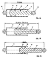
- Fig. 1A shows the shock-absorber in close condition, i.e. with the piston 14 fully inserted into the tubular casing 12.
- Fig. 1B shows the shock-absorber with the piston at middle stroke.
- Fig. 1C shows the shock-absorber in open condition, i.e. with the piston 14 shifted towards the open end of the tubular casing 12.
- the behaviour of the shock-absorber is modified to be adapted to the different operational conditions of the washing machine by changing the shape of the tubular casing 12.
- the specific position of the washing group i.e. the position in height of the rotation centre of the axis of the washing group during the spin phase. It is depending on the weight of the washing group, the weight of the medium charge of the wet linen and the elastic constant of the springs supporting the washing group.
- a shock-absorber having at least a part 22 of the tubular casing 12 with an enlarged cross section.
- the part 22 is obtained in a position intermediate between the two ends of the tubular casing. It is apparent that the braking action is notably different depending from the different positions of the braking elements 18 of the piston 14 within the tubular casing 12. Indeed, when the braking elements 18 are close to one of the two ends of the tubular casing ( Figs.
- the resilient antifriction material of the elements 18 is radially compressed against the internal surface of the tubular casing 12 for a larger extent compared to the compression which is verified when the braking elements 18 are in correspondence of the enlarged section 22 of the tubular casing 12 ( Fig. 2B ).
- shock-absorber This different behaviour of the shock-absorber is important, taking into account the different dynamic stresses, produced on the washing group and transmitted to the floor, in a washing phase at low rotation speed of the drum and in a spinning phase at high rotation speed of the drum, respectively.
- the unbalanced mass of wet linen decreases during the successive spinning phases, due to the discharge of water and consequent weight decrease. Therefore, also the amplitude of the oscillation decreases and the braking action is no longer necessary or at least it is noticeably reduced.
- Figs. 3A to 3C show schematically in axial longitudinal section a shock-absorber according to a second embodiment of the invention. Again, same parts are referred to with same numerals as in previous examples.
- the tubular casing 12 is shaped with two enlarged sections 22 which are spaced apart and positioned in the middle of the tubular casing 12.
- the sections 22 are spaced apart by a distance which is equal to the distance between the braking elements 18.
- radial and axial dimensions of the enlarged cross sections 22 of the tubular casing 12 have to be chosen depending also on the physical properties of the braking elements 18.
Abstract
Description
- The present invention relates to a shock-absorber which is adapted to be used, in particular, in washing machines of domestic type.
- It is known that a washing machine comprises a washing group substantially formed by a tub wherein a drum containing the laundry is assembled and is operated in rotation. The rotation of the drum produces oscillations and vibrations that are transmitted to the support structure of the machine and through it to the floor on which the machine stands. In order to reduce at minimum level said drawback, which arises when the machine is running, the washing group is normally connected to the case of the machine by means of a suspension system comprising springs and shock-absorbers.
- Known shock-absorbers for washing machines are substantially formed by a cylindrical body and a piston, which is encased in the cylindrical body, axially slidable inside the same. The cylindrical body and the piston are connected to the tub and to the base of the machine, respectively. At least a friction element is mounted on the piston rod in such a way to keep a continuous contact with the internal surface of the cylindrical body.
- The friction element is generally formed by a ring made of resilient antifriction material which is covered by a lubricant substance.
-
GB-A-2255600 - Known shock-absorbers produce a braking action which is constant during all the operative phases of the washing machine, i.e. both during pre-washing and washing, when the drum rotates at low speed, and during spinning when the drum rotates at high speed. It is clear that such a behaviour of the shock-absorber is not technically correct and favourable, because it involves a compromise in the project to satisfy the different operational conditions.
-
GB 2 036 247 -
EP 0 256 390 discloses a friction damper with a core part telescopically movable in an outer part. A friction piston is secured to the core part. The friction piston is pot-shaped and includes a basic body and skirt segments. The skirt segments are integral with the basic body and are held by a spring system in frictional contact with the inner surface of the outer part. -
US 3,995,842 discloses a pneumatic spring of the piston-and-cylinder type for use with the engine compartment hood or trunk lid of a motorcar and subject to explosive destruction in the event of an engine fire or a collision is provided with frangible, reduced wall portions in the cylinder and/or in the tubular piston rod which yields under excessive stresses and releases the compressed gas from the cylinder under conditions in which it cannot propel pieces of the fractured spring at high velocity. -
US 3,856,287 discloses a pneumatic spring of adjustable length comprising a piston rod sealed to the cylinder by an annular sealing disc stressed in compression between the inner cylinder wall and a rigid tubular projection on the radial end wall of the cylinder through which the piston rod extends outward of the cylinder cavity. The sealing disc is axially longer than the projection so that it extends inward of the cavity beyond the projection and carries an annular sealing lip engaging the piston rod only under the fluid pressure in the cylinder cavity, but practically fully relieved by the annular projection from the compressive stresses. -
GB 1 162 807 - The object of the present invention is to propose a shock-absorber, in particular for washing machines, which allows to accomplish different braking actions, depending on different operational conditions of the machine, although using the same technology of the present shock-absorbers. It should be noted that the new shock-absorber has to succeed in eliminating braking in the spinning phases, by taking advantage from a specific position and amplitude of oscillation of the washing group.
- The object is achieved with a shock-absorber having the structural characteristics reported in the claims appended to the present patent.
- The invention will be understood better from the following description which is given solely by way of non-limiting example, with reference to the appended drawings, in which:
-
Figs. 1A to 1C show schematically in axial longitudinal section a shock-absorber of known type, in three different operative position ; -
Figs. 2A to 2C show schematically in axial longitudinal section a shock-absorber according to a first embodiment of the invention, in three different operative position; -
Figs. 3A to 3C show schematically in axial longitudinal section a shock-absorber according to a second embodiment of the invention, in three different operative position. - With reference to
Figs. 1A to 1C , it is shown schematically in axial longitudinal section a conventional shock-absorber 10 having an elongatetubular casing 12, made of metal or plastic material, and apiston 14 axially slidable inside thecasing 12. Thecasing 12 has an open end through which thepiston 14 is introduced and a closed end provided with anintegral eye 16, which is adapted to be fixed to the base of the washing machine, e.g. by a pin (not shown). Thepiston 14 is formed by arod 17 and is provided with a plurality ofannular braking elements 18, made of resilient antifriction material. Saidannular braking elements 18 are mounted near the end of the rod which is inserted into thecasing 12. The opposite end of therod 17 is provided with aneye 20, similar to theeye 16 of thecasing 12, which is adapted to be fixed to the lower portion of the washing tub of the machine, e.g. by a pin (not shown). -
Fig. 1A shows the shock-absorber in close condition, i.e. with thepiston 14 fully inserted into thetubular casing 12.Fig. 1B shows the shock-absorber with the piston at middle stroke.Fig. 1C shows the shock-absorber in open condition, i.e. with thepiston 14 shifted towards the open end of thetubular casing 12. - It is apparent that the braking action of a conventional shock-absorber, as described, is always the same at any rotational speed of the washing drum. Indeed, the
braking elements 18 and the internal surface of thetubular casing 12 keep the same contact condition along the entire length of the shock-absorber, due to the fact that the cross sections of the braking elements and the tubular casing are constant, respectively. As already said, this is an unsatisfactory behaviour of the shock-absorber, because the breaking action should be different in response to the variable stresses depending from the different rotational speed of the washing drum. - According to the invention, the behaviour of the shock-absorber is modified to be adapted to the different operational conditions of the washing machine by changing the shape of the
tubular casing 12. - In particular, it is important to consider the specific position of the washing group, i.e. the position in height of the rotation centre of the axis of the washing group during the spin phase. It is depending on the weight of the washing group, the weight of the medium charge of the wet linen and the elastic constant of the springs supporting the washing group.
- With reference to
Figs. 2A to 2C (wherein same parts are referred to with the same numerals as inFigs. 1a to 1C ), it is shown a shock-absorber having at least apart 22 of thetubular casing 12 with an enlarged cross section. Thepart 22 is obtained in a position intermediate between the two ends of the tubular casing. It is apparent that the braking action is notably different depending from the different positions of thebraking elements 18 of thepiston 14 within thetubular casing 12. Indeed, when thebraking elements 18 are close to one of the two ends of the tubular casing (Figs. 2A and 2C ), the resilient antifriction material of theelements 18 is radially compressed against the internal surface of thetubular casing 12 for a larger extent compared to the compression which is verified when thebraking elements 18 are in correspondence of the enlargedsection 22 of the tubular casing 12 (Fig. 2B ). - This different behaviour of the shock-absorber is important, taking into account the different dynamic stresses, produced on the washing group and transmitted to the floor, in a washing phase at low rotation speed of the drum and in a spinning phase at high rotation speed of the drum, respectively. Moreover, there is the need of a strong breaking action at the beginning of the spinning phase to limit the amplitude of oscillation of the washing group. Then, the unbalanced mass of wet linen decreases during the successive spinning phases, due to the discharge of water and consequent weight decrease. Therefore, also the amplitude of the oscillation decreases and the braking action is no longer necessary or at least it is noticeably reduced.
-
Figs. 3A to 3C show schematically in axial longitudinal section a shock-absorber according to a second embodiment of the invention. Again, same parts are referred to with same numerals as in previous examples. - In this case, the
tubular casing 12 is shaped with twoenlarged sections 22 which are spaced apart and positioned in the middle of thetubular casing 12. Preferably, thesections 22 are spaced apart by a distance which is equal to the distance between thebraking elements 18. Said solution allows to obtain a braking effect which is more differentiated with respect to that of the previous one, in order to respond to specific needs depending on the structural and functional characteristics of the machine on which the shock-absorber has to be mounted. - To be noted that radial and axial dimensions of the
enlarged cross sections 22 of thetubular casing 12 have to be chosen depending also on the physical properties of thebraking elements 18. - The description before refers to a shock-absorber whose tubular casing is provided with one or more enlarged cross section; however, it is apparent that it is possible to arrange an alternative solution, wherein the tubular casing is provided with one or more restricted cross section. The same technical process (e.g. cross rolling) can be used in both cases. The choice is depending on the requested characteristic of the shock-absorber, in view of the specific machine to which it has to be applied.
Claims (3)
- Shock-absorber, in particular for washing machines, comprising a tubular casing (12) and a piston (14), which is axially slidable inside the tubular casing (12), at least a braking element (18) made of resilient antifriction material is mounted on the piston rod (17) to keep a continuous contact of the brake element with the internal surface of the tubular casing (12), the casing (12) having an open end through which the piston (14) is introduced and a closed end, characterised in that at least a part (22) of the tubular casing (12) has an enlarged cross section or a restricted cross section with respect to the rest of the casing (12), said part being obtained in a position intermediate between the two ends of the tubular casing (12), so that, when the braking element (18) is in correspondence of said part (22) of the tubular casing (12), the resilient antifriction material of the braking element (18) is radially compressed against the internal surface of the tubular casing (12) for a different extent compared to the compression which is verified when the braking element (18) is in correspondence of one of the two ends of the tubular casing (12).
- Shock-absorber according to claim 1, wherein at least two braking elements (18) are mounted spaced apart on the piston rod (17), characterised in that the tubular casing (12) is provided with two enlarged sections (22) spaced apart by a distance which is equal to the distance between the braking elements (18).
- Washing machine characterised by comprising the shock-absorber according to claim 1 or 2.
Priority Applications (6)
| Application Number | Priority Date | Filing Date | Title |
|---|---|---|---|
| DE602007012993T DE602007012993D1 (en) | 2007-01-15 | 2007-01-15 | Shock absorbers, in particular for washing machines |
| ES07100528T ES2363730T3 (en) | 2007-01-15 | 2007-01-15 | SHOCK ABSORBER, IN PARTICULAR FOR WASHING MACHINES. |
| PL07100528T PL1944402T3 (en) | 2007-01-15 | 2007-01-15 | Shock-absorber, in particular for washing machines |
| EP07100528A EP1944402B1 (en) | 2007-01-15 | 2007-01-15 | Shock-absorber, in particular for washing machines |
| AT07100528T ATE501295T1 (en) | 2007-01-15 | 2007-01-15 | SHOCK ABSORBERS, ESPECIALLY FOR WASHING MACHINES |
| RU2008101539/12A RU2435885C2 (en) | 2007-01-15 | 2008-01-14 | Shock absorber in particular for washing machines |
Applications Claiming Priority (1)
| Application Number | Priority Date | Filing Date | Title |
|---|---|---|---|
| EP07100528A EP1944402B1 (en) | 2007-01-15 | 2007-01-15 | Shock-absorber, in particular for washing machines |
Publications (2)
| Publication Number | Publication Date |
|---|---|
| EP1944402A1 EP1944402A1 (en) | 2008-07-16 |
| EP1944402B1 true EP1944402B1 (en) | 2011-03-09 |
Family
ID=38050210
Family Applications (1)
| Application Number | Title | Priority Date | Filing Date |
|---|---|---|---|
| EP07100528A Not-in-force EP1944402B1 (en) | 2007-01-15 | 2007-01-15 | Shock-absorber, in particular for washing machines |
Country Status (6)
| Country | Link |
|---|---|
| EP (1) | EP1944402B1 (en) |
| AT (1) | ATE501295T1 (en) |
| DE (1) | DE602007012993D1 (en) |
| ES (1) | ES2363730T3 (en) |
| PL (1) | PL1944402T3 (en) |
| RU (1) | RU2435885C2 (en) |
Cited By (2)
| Publication number | Priority date | Publication date | Assignee | Title |
|---|---|---|---|---|
| DE102013109196A1 (en) | 2013-08-26 | 2015-02-26 | Miele & Cie. Kg | Friction damper, in particular for a drum washing machine |
| DE102013109198A1 (en) | 2013-08-26 | 2015-02-26 | Miele & Cie. Kg | Friction damper, in particular for drum washing machines |
Families Citing this family (3)
| Publication number | Priority date | Publication date | Assignee | Title |
|---|---|---|---|---|
| CN103953676B (en) | 2014-05-14 | 2015-10-21 | 北京京西重工有限公司 | There is hydraulic damper and the manufacture method thereof of hydraulic pressure stop configurations |
| DE202014103664U1 (en) * | 2014-08-06 | 2015-08-07 | Seuffer gmbH & Co. KG | Device for damping vibrations of a body |
| US10107352B2 (en) | 2016-04-29 | 2018-10-23 | Beijingwest Industries Co., Ltd. | Hydraulic damper with a hydraulic stop arrangement |
Family Cites Families (6)
| Publication number | Priority date | Publication date | Assignee | Title |
|---|---|---|---|---|
| DE2231050A1 (en) * | 1972-06-24 | 1974-01-17 | Stabilus Gmbh | PISTON ROD SEAL FOR GAS SPRINGS WITH SEALING LIP SUPPORTED ON THE GUIDE |
| DE2457938C2 (en) * | 1974-12-07 | 1982-10-28 | Stabilus Gmbh, 5400 Koblenz | Safety gas spring |
| DE2849267A1 (en) * | 1978-11-14 | 1980-05-29 | Stabilus Gmbh | GAS SPRING WITH ADDITIONAL ADJUSTMENT RANGE |
| DE3627816A1 (en) * | 1986-08-16 | 1988-02-18 | Stabilus Gmbh | FRICTION DAMPER |
| IT225645Y1 (en) * | 1991-05-08 | 1997-01-13 | Zanussi Elettrodomestici | SHOCK ABSORBER FOR WASHING MACHINES |
| DE10360833A1 (en) * | 2003-12-23 | 2005-07-21 | Bayerische Motoren Werke Ag | Throttle control e.g. for front hood of motor vehicle, has cylinder with piston inside which can move with piston rod between lower final section and upper final section |
-
2007
- 2007-01-15 EP EP07100528A patent/EP1944402B1/en not_active Not-in-force
- 2007-01-15 ES ES07100528T patent/ES2363730T3/en active Active
- 2007-01-15 DE DE602007012993T patent/DE602007012993D1/en active Active
- 2007-01-15 PL PL07100528T patent/PL1944402T3/en unknown
- 2007-01-15 AT AT07100528T patent/ATE501295T1/en not_active IP Right Cessation
-
2008
- 2008-01-14 RU RU2008101539/12A patent/RU2435885C2/en not_active IP Right Cessation
Cited By (4)
| Publication number | Priority date | Publication date | Assignee | Title |
|---|---|---|---|---|
| DE102013109196A1 (en) | 2013-08-26 | 2015-02-26 | Miele & Cie. Kg | Friction damper, in particular for a drum washing machine |
| DE102013109198A1 (en) | 2013-08-26 | 2015-02-26 | Miele & Cie. Kg | Friction damper, in particular for drum washing machines |
| EP2848724A1 (en) | 2013-08-26 | 2015-03-18 | Miele & Cie. KG | Friction damper, especially for washing machines having a drum |
| DE102013109196B4 (en) | 2013-08-26 | 2023-03-02 | Miele & Cie. Kg | Friction damper, in particular for a drum washing machine |
Also Published As
| Publication number | Publication date |
|---|---|
| ATE501295T1 (en) | 2011-03-15 |
| RU2008101539A (en) | 2009-07-20 |
| RU2435885C2 (en) | 2011-12-10 |
| DE602007012993D1 (en) | 2011-04-21 |
| EP1944402A1 (en) | 2008-07-16 |
| ES2363730T3 (en) | 2011-08-12 |
| PL1944402T3 (en) | 2011-10-31 |
Similar Documents
| Publication | Publication Date | Title |
|---|---|---|
| EP1944402B1 (en) | Shock-absorber, in particular for washing machines | |
| US5549182A (en) | Frictional damper, in particular for spinner-type washing machines | |
| JP3713562B2 (en) | Friction damper for washing machine | |
| KR950003213B1 (en) | Air spring suspension system | |
| EP2725130B1 (en) | Shock absorber having an improved friction element | |
| CN100396954C (en) | Vibration absorber for movable unit of furniture | |
| CN1312348C (en) | Damper for drum type washing machine | |
| HU188394B (en) | Friction vibration damper for damped machines and devices particularly rotary-drum washers | |
| US9618073B2 (en) | Shock absorber having an improved friction element | |
| US7293634B2 (en) | Hydraulic vehicle shock absorber | |
| RU2340468C1 (en) | Pneumatic suspension | |
| US2088450A (en) | Shock absorber | |
| US5186439A (en) | Friction compensating automotive suspension strut | |
| US11359690B2 (en) | Shock absorber | |
| CN104514118A (en) | Vibration absorption damper for automatic washer | |
| CN111981076B (en) | Hydraulic buffer for automobile | |
| US20030160367A1 (en) | Shock absorber | |
| RU2696049C1 (en) | Rear wheel suspension | |
| EP2994663B1 (en) | Multi-action anti-vibration frictional shock absorber | |
| RU195304U1 (en) | Shock absorber | |
| JP5812426B2 (en) | Spring load adjusting device for shock absorber | |
| KR100791469B1 (en) | Shock absorber | |
| KR100478908B1 (en) | Structure for support head cap use in a shock absorber | |
| KR100757809B1 (en) | Bumper rubber for use in a shock absorber | |
| KR20050054326A (en) | Bumper rubber fixing structure of a shock absorber |
Legal Events
| Date | Code | Title | Description |
|---|---|---|---|
| PUAI | Public reference made under article 153(3) epc to a published international application that has entered the european phase |
Free format text: ORIGINAL CODE: 0009012 |
|
| AK | Designated contracting states |
Kind code of ref document: A1 Designated state(s): AT BE BG CH CY CZ DE DK EE ES FI FR GB GR HU IE IS IT LI LT LU LV MC NL PL PT RO SE SI SK TR |
|
| AX | Request for extension of the european patent |
Extension state: AL BA HR MK RS |
|
| 17P | Request for examination filed |
Effective date: 20081222 |
|
| 17Q | First examination report despatched |
Effective date: 20090128 |
|
| AKX | Designation fees paid |
Designated state(s): AT BE BG CH CY CZ DE DK EE ES FI FR GB GR HU IE IS IT LI LT LU LV MC NL PL PT RO SE SI SK TR |
|
| GRAP | Despatch of communication of intention to grant a patent |
Free format text: ORIGINAL CODE: EPIDOSNIGR1 |
|
| GRAS | Grant fee paid |
Free format text: ORIGINAL CODE: EPIDOSNIGR3 |
|
| GRAA | (expected) grant |
Free format text: ORIGINAL CODE: 0009210 |
|
| AK | Designated contracting states |
Kind code of ref document: B1 Designated state(s): AT BE BG CH CY CZ DE DK EE ES FI FR GB GR HU IE IS IT LI LT LU LV MC NL PL PT RO SE SI SK TR |
|
| REG | Reference to a national code |
Ref country code: GB Ref legal event code: FG4D |
|
| REG | Reference to a national code |
Ref country code: CH Ref legal event code: EP |
|
| RAP2 | Party data changed (patent owner data changed or rights of a patent transferred) |
Owner name: ELECTROLUX HOME PRODUCTS CORPORATION N.V. |
|
| REG | Reference to a national code |
Ref country code: IE Ref legal event code: FG4D |
|
| REF | Corresponds to: |
Ref document number: 602007012993 Country of ref document: DE Date of ref document: 20110421 Kind code of ref document: P |
|
| REG | Reference to a national code |
Ref country code: DE Ref legal event code: R096 Ref document number: 602007012993 Country of ref document: DE Effective date: 20110421 |
|
| RAP2 | Party data changed (patent owner data changed or rights of a patent transferred) |
Owner name: ELECTROLUX HOME PRODUCTS CORPORATION N.V. |
|
| REG | Reference to a national code |
Ref country code: NL Ref legal event code: VDEP Effective date: 20110309 |
|
| PG25 | Lapsed in a contracting state [announced via postgrant information from national office to epo] |
Ref country code: SE Free format text: LAPSE BECAUSE OF FAILURE TO SUBMIT A TRANSLATION OF THE DESCRIPTION OR TO PAY THE FEE WITHIN THE PRESCRIBED TIME-LIMIT Effective date: 20110309 Ref country code: LV Free format text: LAPSE BECAUSE OF FAILURE TO SUBMIT A TRANSLATION OF THE DESCRIPTION OR TO PAY THE FEE WITHIN THE PRESCRIBED TIME-LIMIT Effective date: 20110309 Ref country code: LT Free format text: LAPSE BECAUSE OF FAILURE TO SUBMIT A TRANSLATION OF THE DESCRIPTION OR TO PAY THE FEE WITHIN THE PRESCRIBED TIME-LIMIT Effective date: 20110309 Ref country code: GR Free format text: LAPSE BECAUSE OF FAILURE TO SUBMIT A TRANSLATION OF THE DESCRIPTION OR TO PAY THE FEE WITHIN THE PRESCRIBED TIME-LIMIT Effective date: 20110610 |
|
| REG | Reference to a national code |
Ref country code: ES Ref legal event code: FG2A Ref document number: 2363730 Country of ref document: ES Kind code of ref document: T3 Effective date: 20110812 |
|
| LTIE | Lt: invalidation of european patent or patent extension |
Effective date: 20110309 |
|
| PG25 | Lapsed in a contracting state [announced via postgrant information from national office to epo] |
Ref country code: FI Free format text: LAPSE BECAUSE OF FAILURE TO SUBMIT A TRANSLATION OF THE DESCRIPTION OR TO PAY THE FEE WITHIN THE PRESCRIBED TIME-LIMIT Effective date: 20110309 Ref country code: SI Free format text: LAPSE BECAUSE OF FAILURE TO SUBMIT A TRANSLATION OF THE DESCRIPTION OR TO PAY THE FEE WITHIN THE PRESCRIBED TIME-LIMIT Effective date: 20110309 Ref country code: CY Free format text: LAPSE BECAUSE OF FAILURE TO SUBMIT A TRANSLATION OF THE DESCRIPTION OR TO PAY THE FEE WITHIN THE PRESCRIBED TIME-LIMIT Effective date: 20110309 Ref country code: NL Free format text: LAPSE BECAUSE OF FAILURE TO SUBMIT A TRANSLATION OF THE DESCRIPTION OR TO PAY THE FEE WITHIN THE PRESCRIBED TIME-LIMIT Effective date: 20110309 Ref country code: AT Free format text: LAPSE BECAUSE OF FAILURE TO SUBMIT A TRANSLATION OF THE DESCRIPTION OR TO PAY THE FEE WITHIN THE PRESCRIBED TIME-LIMIT Effective date: 20110309 Ref country code: BG Free format text: LAPSE BECAUSE OF FAILURE TO SUBMIT A TRANSLATION OF THE DESCRIPTION OR TO PAY THE FEE WITHIN THE PRESCRIBED TIME-LIMIT Effective date: 20110609 |
|
| PG25 | Lapsed in a contracting state [announced via postgrant information from national office to epo] |
Ref country code: BE Free format text: LAPSE BECAUSE OF FAILURE TO SUBMIT A TRANSLATION OF THE DESCRIPTION OR TO PAY THE FEE WITHIN THE PRESCRIBED TIME-LIMIT Effective date: 20110309 |
|
| PG25 | Lapsed in a contracting state [announced via postgrant information from national office to epo] |
Ref country code: PT Free format text: LAPSE BECAUSE OF FAILURE TO SUBMIT A TRANSLATION OF THE DESCRIPTION OR TO PAY THE FEE WITHIN THE PRESCRIBED TIME-LIMIT Effective date: 20110711 Ref country code: EE Free format text: LAPSE BECAUSE OF FAILURE TO SUBMIT A TRANSLATION OF THE DESCRIPTION OR TO PAY THE FEE WITHIN THE PRESCRIBED TIME-LIMIT Effective date: 20110309 |
|
| REG | Reference to a national code |
Ref country code: PL Ref legal event code: T3 |
|
| PG25 | Lapsed in a contracting state [announced via postgrant information from national office to epo] |
Ref country code: RO Free format text: LAPSE BECAUSE OF FAILURE TO SUBMIT A TRANSLATION OF THE DESCRIPTION OR TO PAY THE FEE WITHIN THE PRESCRIBED TIME-LIMIT Effective date: 20110309 Ref country code: IS Free format text: LAPSE BECAUSE OF FAILURE TO SUBMIT A TRANSLATION OF THE DESCRIPTION OR TO PAY THE FEE WITHIN THE PRESCRIBED TIME-LIMIT Effective date: 20110709 Ref country code: SK Free format text: LAPSE BECAUSE OF FAILURE TO SUBMIT A TRANSLATION OF THE DESCRIPTION OR TO PAY THE FEE WITHIN THE PRESCRIBED TIME-LIMIT Effective date: 20110309 Ref country code: CZ Free format text: LAPSE BECAUSE OF FAILURE TO SUBMIT A TRANSLATION OF THE DESCRIPTION OR TO PAY THE FEE WITHIN THE PRESCRIBED TIME-LIMIT Effective date: 20110309 |
|
| PLBE | No opposition filed within time limit |
Free format text: ORIGINAL CODE: 0009261 |
|
| STAA | Information on the status of an ep patent application or granted ep patent |
Free format text: STATUS: NO OPPOSITION FILED WITHIN TIME LIMIT |
|
| 26N | No opposition filed |
Effective date: 20111212 |
|
| PG25 | Lapsed in a contracting state [announced via postgrant information from national office to epo] |
Ref country code: DK Free format text: LAPSE BECAUSE OF FAILURE TO SUBMIT A TRANSLATION OF THE DESCRIPTION OR TO PAY THE FEE WITHIN THE PRESCRIBED TIME-LIMIT Effective date: 20110309 |
|
| REG | Reference to a national code |
Ref country code: DE Ref legal event code: R097 Ref document number: 602007012993 Country of ref document: DE Effective date: 20111212 |
|
| PG25 | Lapsed in a contracting state [announced via postgrant information from national office to epo] |
Ref country code: MC Free format text: LAPSE BECAUSE OF NON-PAYMENT OF DUE FEES Effective date: 20120131 |
|
| REG | Reference to a national code |
Ref country code: CH Ref legal event code: PL |
|
| REG | Reference to a national code |
Ref country code: IE Ref legal event code: MM4A |
|
| PG25 | Lapsed in a contracting state [announced via postgrant information from national office to epo] |
Ref country code: CH Free format text: LAPSE BECAUSE OF NON-PAYMENT OF DUE FEES Effective date: 20120131 Ref country code: LI Free format text: LAPSE BECAUSE OF NON-PAYMENT OF DUE FEES Effective date: 20120131 |
|
| PG25 | Lapsed in a contracting state [announced via postgrant information from national office to epo] |
Ref country code: IE Free format text: LAPSE BECAUSE OF NON-PAYMENT OF DUE FEES Effective date: 20120115 |
|
| PGFP | Annual fee paid to national office [announced via postgrant information from national office to epo] |
Ref country code: PL Payment date: 20121224 Year of fee payment: 7 |
|
| PGFP | Annual fee paid to national office [announced via postgrant information from national office to epo] |
Ref country code: ES Payment date: 20130128 Year of fee payment: 7 |
|
| PG25 | Lapsed in a contracting state [announced via postgrant information from national office to epo] |
Ref country code: TR Free format text: LAPSE BECAUSE OF FAILURE TO SUBMIT A TRANSLATION OF THE DESCRIPTION OR TO PAY THE FEE WITHIN THE PRESCRIBED TIME-LIMIT Effective date: 20110309 |
|
| PG25 | Lapsed in a contracting state [announced via postgrant information from national office to epo] |
Ref country code: LU Free format text: LAPSE BECAUSE OF NON-PAYMENT OF DUE FEES Effective date: 20120115 |
|
| PG25 | Lapsed in a contracting state [announced via postgrant information from national office to epo] |
Ref country code: HU Free format text: LAPSE BECAUSE OF FAILURE TO SUBMIT A TRANSLATION OF THE DESCRIPTION OR TO PAY THE FEE WITHIN THE PRESCRIBED TIME-LIMIT Effective date: 20070115 |
|
| REG | Reference to a national code |
Ref country code: PL Ref legal event code: LAPE |
|
| PG25 | Lapsed in a contracting state [announced via postgrant information from national office to epo] |
Ref country code: PL Free format text: LAPSE BECAUSE OF NON-PAYMENT OF DUE FEES Effective date: 20140115 |
|
| REG | Reference to a national code |
Ref country code: FR Ref legal event code: PLFP Year of fee payment: 10 |
|
| PG25 | Lapsed in a contracting state [announced via postgrant information from national office to epo] |
Ref country code: ES Free format text: LAPSE BECAUSE OF NON-PAYMENT OF DUE FEES Effective date: 20140116 |
|
| REG | Reference to a national code |
Ref country code: FR Ref legal event code: PLFP Year of fee payment: 11 |
|
| PGFP | Annual fee paid to national office [announced via postgrant information from national office to epo] |
Ref country code: FR Payment date: 20170120 Year of fee payment: 11 |
|
| PGFP | Annual fee paid to national office [announced via postgrant information from national office to epo] |
Ref country code: GB Payment date: 20170119 Year of fee payment: 11 |
|
| PGFP | Annual fee paid to national office [announced via postgrant information from national office to epo] |
Ref country code: IT Payment date: 20170124 Year of fee payment: 11 |
|
| GBPC | Gb: european patent ceased through non-payment of renewal fee |
Effective date: 20180115 |
|
| PG25 | Lapsed in a contracting state [announced via postgrant information from national office to epo] |
Ref country code: FR Free format text: LAPSE BECAUSE OF NON-PAYMENT OF DUE FEES Effective date: 20180131 |
|
| REG | Reference to a national code |
Ref country code: FR Ref legal event code: ST Effective date: 20180928 |
|
| PG25 | Lapsed in a contracting state [announced via postgrant information from national office to epo] |
Ref country code: GB Free format text: LAPSE BECAUSE OF NON-PAYMENT OF DUE FEES Effective date: 20180115 |
|
| PG25 | Lapsed in a contracting state [announced via postgrant information from national office to epo] |
Ref country code: IT Free format text: LAPSE BECAUSE OF NON-PAYMENT OF DUE FEES Effective date: 20180115 |
|
| PGFP | Annual fee paid to national office [announced via postgrant information from national office to epo] |
Ref country code: DE Payment date: 20210120 Year of fee payment: 15 |
|
| REG | Reference to a national code |
Ref country code: DE Ref legal event code: R119 Ref document number: 602007012993 Country of ref document: DE |
|
| PG25 | Lapsed in a contracting state [announced via postgrant information from national office to epo] |
Ref country code: DE Free format text: LAPSE BECAUSE OF NON-PAYMENT OF DUE FEES Effective date: 20220802 |