EP1943474B1 - Anlage zur herstellung von zementklinker - Google Patents
Anlage zur herstellung von zementklinker Download PDFInfo
- Publication number
- EP1943474B1 EP1943474B1 EP07725402A EP07725402A EP1943474B1 EP 1943474 B1 EP1943474 B1 EP 1943474B1 EP 07725402 A EP07725402 A EP 07725402A EP 07725402 A EP07725402 A EP 07725402A EP 1943474 B1 EP1943474 B1 EP 1943474B1
- Authority
- EP
- European Patent Office
- Prior art keywords
- section
- cross
- adjusting
- calcining
- nozzle
- Prior art date
- Legal status (The legal status is an assumption and is not a legal conclusion. Google has not performed a legal analysis and makes no representation as to the accuracy of the status listed.)
- Not-in-force
Links
- 239000004568 cement Substances 0.000 title claims description 30
- 239000007789 gas Substances 0.000 claims description 24
- 238000001354 calcination Methods 0.000 claims description 23
- 235000012054 meals Nutrition 0.000 claims description 18
- 238000005245 sintering Methods 0.000 claims description 11
- 238000001816 cooling Methods 0.000 claims description 10
- 230000000694 effects Effects 0.000 claims description 6
- 238000010304 firing Methods 0.000 claims description 2
- 238000004519 manufacturing process Methods 0.000 description 6
- 239000002826 coolant Substances 0.000 description 3
- 239000000446 fuel Substances 0.000 description 3
- 238000013461 design Methods 0.000 description 2
- 238000002156 mixing Methods 0.000 description 2
- 230000003466 anti-cipated effect Effects 0.000 description 1
- 238000013459 approach Methods 0.000 description 1
- QVGXLLKOCUKJST-UHFFFAOYSA-N atomic oxygen Chemical compound [O] QVGXLLKOCUKJST-UHFFFAOYSA-N 0.000 description 1
- 230000015572 biosynthetic process Effects 0.000 description 1
- 238000002485 combustion reaction Methods 0.000 description 1
- 230000001419 dependent effect Effects 0.000 description 1
- 239000000428 dust Substances 0.000 description 1
- 238000003780 insertion Methods 0.000 description 1
- 230000037431 insertion Effects 0.000 description 1
- 238000007689 inspection Methods 0.000 description 1
- 238000009434 installation Methods 0.000 description 1
- 238000012423 maintenance Methods 0.000 description 1
- 230000013011 mating Effects 0.000 description 1
- 238000000034 method Methods 0.000 description 1
- 239000001301 oxygen Substances 0.000 description 1
- 229910052760 oxygen Inorganic materials 0.000 description 1
- 239000002994 raw material Substances 0.000 description 1
- 239000011819 refractory material Substances 0.000 description 1
- 239000000126 substance Substances 0.000 description 1
- 238000012549 training Methods 0.000 description 1
- XLYOFNOQVPJJNP-UHFFFAOYSA-N water Substances O XLYOFNOQVPJJNP-UHFFFAOYSA-N 0.000 description 1
Images




Classifications
-
- F—MECHANICAL ENGINEERING; LIGHTING; HEATING; WEAPONS; BLASTING
- F27—FURNACES; KILNS; OVENS; RETORTS
- F27B—FURNACES, KILNS, OVENS OR RETORTS IN GENERAL; OPEN SINTERING OR LIKE APPARATUS
- F27B7/00—Rotary-drum furnaces, i.e. horizontal or slightly inclined
- F27B7/20—Details, accessories or equipment specially adapted for rotary-drum furnaces
- F27B7/2016—Arrangements of preheating devices for the charge
- F27B7/2025—Arrangements of preheating devices for the charge consisting of a single string of cyclones
- F27B7/2033—Arrangements of preheating devices for the charge consisting of a single string of cyclones with means for precalcining the raw material
-
- C—CHEMISTRY; METALLURGY
- C04—CEMENTS; CONCRETE; ARTIFICIAL STONE; CERAMICS; REFRACTORIES
- C04B—LIME, MAGNESIA; SLAG; CEMENTS; COMPOSITIONS THEREOF, e.g. MORTARS, CONCRETE OR LIKE BUILDING MATERIALS; ARTIFICIAL STONE; CERAMICS; REFRACTORIES; TREATMENT OF NATURAL STONE
- C04B7/00—Hydraulic cements
- C04B7/36—Manufacture of hydraulic cements in general
- C04B7/43—Heat treatment, e.g. precalcining, burning, melting; Cooling
- C04B7/434—Preheating with addition of fuel, e.g. calcining
-
- F—MECHANICAL ENGINEERING; LIGHTING; HEATING; WEAPONS; BLASTING
- F16—ENGINEERING ELEMENTS AND UNITS; GENERAL MEASURES FOR PRODUCING AND MAINTAINING EFFECTIVE FUNCTIONING OF MACHINES OR INSTALLATIONS; THERMAL INSULATION IN GENERAL
- F16K—VALVES; TAPS; COCKS; ACTUATING-FLOATS; DEVICES FOR VENTING OR AERATING
- F16K1/00—Lift valves or globe valves, i.e. cut-off apparatus with closure members having at least a component of their opening and closing motion perpendicular to the closing faces
- F16K1/16—Lift valves or globe valves, i.e. cut-off apparatus with closure members having at least a component of their opening and closing motion perpendicular to the closing faces with pivoted closure-members
- F16K1/165—Lift valves or globe valves, i.e. cut-off apparatus with closure members having at least a component of their opening and closing motion perpendicular to the closing faces with pivoted closure-members with a plurality of closure members
-
- F—MECHANICAL ENGINEERING; LIGHTING; HEATING; WEAPONS; BLASTING
- F16—ENGINEERING ELEMENTS AND UNITS; GENERAL MEASURES FOR PRODUCING AND MAINTAINING EFFECTIVE FUNCTIONING OF MACHINES OR INSTALLATIONS; THERMAL INSULATION IN GENERAL
- F16K—VALVES; TAPS; COCKS; ACTUATING-FLOATS; DEVICES FOR VENTING OR AERATING
- F16K5/00—Plug valves; Taps or cocks comprising only cut-off apparatus having at least one of the sealing faces shaped as a more or less complete surface of a solid of revolution, the opening and closing movement being predominantly rotary
- F16K5/04—Plug valves; Taps or cocks comprising only cut-off apparatus having at least one of the sealing faces shaped as a more or less complete surface of a solid of revolution, the opening and closing movement being predominantly rotary with plugs having cylindrical surfaces; Packings therefor
Definitions
- the invention relates to a plant for the production of cement clinker from raw meal with a preheater for preheating the cement raw meal, a Calcinier situated for precalcining the preheated raw meal, a sintering furnace for Fertigbines the precalcined cement raw meal to cement clinker and a cooler for cooling the fired cement clinker.
- the calcining device flows through the exhaust gases of the sintering furnace and on the other hand receives tertiary air via a tertiary air line provided between the cooler and the calcining device. Since these two gas streams are very different in their temperature and especially in their oxygen content, it is known to provide a slide in the tertiary air line in order to adjust the distribution between the exhaust gas and tertiary air can.
- the Calcinier worn also has in its initial area on a Calcinatordüse, which is usually formed by a constriction in the riser. The selected cross-sectional area of the Calcinatordüse forms a compromise to the anticipated during start-up, part load and rated operation flow conditions.
- the fine adjustment of the gas distribution is realized in the operation of the system alone via the tertiary air valve. If the operation of the system differs greatly from the design point, there is a risk that regulation of the gas distribution via the movement of the tertiary air valve is no longer possible. This mostly results from deposits of clinker dust in the tertiary air line due to longer-term partial load operation. On the other hand, when using particulate fuels, increasing the gas velocity in the calciner nozzle is desirable.
- the EP-A-1 167 314 discloses a plant for the production of cement clinker in which in the rotary kiln exhaust duct opens a tertiary air duct, wherein a pivotable throttle valve is provided in front of the junction.
- the invention is therefore based on the object to further develop the means for adjusting the cross section of the calciner to the effect that an adjustment of the nozzle during operation of the system in a simple manner is possible.
- the inventive plant for the production of cement clinker from cement raw meal consists essentially of a preheater for preheating the cement raw meal, a Calcinier adopted for precalcining the preheated cement raw meal, a sintering furnace for Fertigbines the precalcined cement raw meal to cement clinker and a cooler for cooling the fired cement clinker. Between the cooler and the calcining device, a tertiary air line is furthermore provided, via which tertiary air is supplied to the calcining device.
- the calciner is also flowed through by the exhaust gases of the sintering furnace and has a calciner nozzle in its initial region.
- means are provided for adjusting the cross section of the Calcinatordüse, which are formed by at least one element which is rotatably arranged to adjust the cross section and exposed to the exhaust gases of the sintering furnace, wherein that at least one element for adjusting the cross section in the region of a bulge the calciner is arranged and the element for enlarging the Calcinatordüse is at least partially rotatable or pivotable in the bulge.
- a rotatably or pivotally arranged means for adjusting the cross section of the calciner nozzle is compared to a horizontally displaceable flat slide much easier and reliable seal and less sensitive to approach.
- the adjustment of the element during the operation of the Calcinier drove in a simple manner, in particular automated realize.
- two oppositely arranged elements are provided for adjusting the cross section.
- the at least one element for adjusting the cross section is designed and arranged such that it can be actuated from outside during the operation of the calcining device.
- the at least one element for adjusting the cross section is preferably mounted on both sides.
- means for cooling the at least one element for adjusting the cross section are provided.
- the element for adjusting the cross section is formed in one embodiment by a pendulum that is pivotable so that it causes a change in the cross section of the Calcinatordüse.
- the element is formed by a cylinder cutout or cylinder section.
- the element consists of a segment-like disc.
- the element does not necessarily have to be rotationally symmetrical.
- the elements for adjusting the cross section are preferably protected against heat and wear. It also means for protection against chemical attack can be provided.
- the drive of the movable elements for changing the cross section can be done for example via its pivot axis or over its circumference.
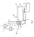
- the im Fig. 1 Plant for the production of cement clinker from cement raw meal shown consists essentially of a preheater 1 for preheating the cement raw meal, a Calcinier adopted 2 for precalcining the preheated cement raw meal, a sintering furnace 3 for final firing of precalcined cement raw meal to cement clinker and a cooler 4 for cooling the fired cement clinker.
- a tertiary air line 5 is provided between the cooler 4 and the calcining device 2 in order to be able to supply tertiary air 6 to the calcining device.
- the calcining device 2 is also flowed through by exhaust gases 7 of the sintering furnace 3.
- the calcining device has a calciner nozzle 8.
- a slide or other adjusting means 15 is provided in the tertiary air duct 5 and, on the other hand, means for adjusting the cross section of the calciner jet are arranged in the region of the calciner jet 8.
- These means for adjusting the cross section of the Calcinatordüse be formed by at least one element 9, which is arranged to adjust the cross section rotatably and pivotally and the exhaust gases 7 of the sintering furnace 3 is exposed.
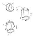
- This in Fig. 2a illustrated element 9 for adjusting the cross section of the calciner is formed by a cylinder section or cylinder section, in particular a cylinder segment 9.1.
- This cylinder segment which may in particular have an angle in the range of 90 ° -180 °, is closed at both ends by a respective cylindrical end plate 9.2.
- the element 9 is mounted in the region of the calciner nozzle via a shaft or two shaft journals 9.3 such that the element 9 can execute a rotational movement. From the Fig. 2d-2f Various settings for the element 9 in the area of calciner 8 are shown.
- two oppositely arranged elements 9 are provided for adjusting the cross section.
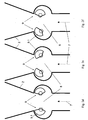
- Fig. 2d the two elements 9 are set so that the largest possible cross section for the Calcinatordüse 8 results.
- Fig. 2e the cross section is reduced by both elements 9, while in Fig. 2f a one-sided cross-section reduction is shown.
- a deflection of the exhaust gas stream 7 can be effected.
- the calcining device receives an additional degree of freedom in the flow guidance of the exhaust gases in order to ensure better mixing ratios in the region of the calciner burner 16.
- the element 9 is preferably formed as a hollow body, which is equipped with a refractory jacket 9.4, so that the element keeps the over 1000 ° C hot exhaust gases 7 state.
- the training as a hollow body also offers the possibility of cooling, as later with reference to the Fig. 7 is explained in more detail.
- the element 9 according to the Fig. 2a and 2b is designed as a cylinder segment 9.1
- the element 9 essentially depends only on that it is designed such that it can effect a change in the cross section of the calciner nozzle during a rotational or pivoting movement.
- the element 9 for adjusting the cross section of the calciner nozzle is designed as a pendulum 9.6, which is pivotable such that it causes a change in the cross section of the calciner nozzle.
- Fig. 4a-4b is an embodiment in which the elements 9 are set to adjust the cross section of the Calcinatordüse by segment-like discs 9.7, which are rotatably mounted to change the cross section of the calciner 8.
- the angle between the axis of rotation 9.13 and the flow direction of the exhaust gases 7 is preferably in the range between 0 and 60 °.
- the element 9 is mounted on the housing of the calciner 2, wherein seals are used, which are arranged either directly on the shaft or the shaft journal 9.3 or in the region of the circumference, in particular in the region of the end plates 9.2 of the element 9.
- Fig. 5a shows a portion of the element 9 in the region of the connection to the housing of the calciner 2.
- Fig. 5b is a detail of this connection shown in more detail.
- the element 9 has in particular a flange 9.8, which is connected at one end fixed to the housing 2.
- the other end of the flange is formed as a mating surface 9.9 for the rotatable part of the element 9.
- the seal is made here by an inner and an outer seal 9.10, 9.11.
- the two seals rotate with the rotatable part of the element 9 and are formed for example as V-rings.
- the element 9 for adjusting the cross section is preferably mounted on both sides, wherein it is expediently held in the region of its shaft or its shaft journals 9.3 in two bearings arranged outside the calcining device 2.
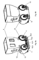
- the drive of the element 9 is advantageously carried out on the outside of the calcining device and, depending on the design of the element 9 on the Shaft or shaft journal 9.3 or over its circumference, with suitable means 10 are provided for driving the element 9.
- each element 9 is associated with a drive motor 10.1 and 10.2, which are each connected via a drive train 10.3, 10.4 with the circumference of the led out through the housing of Calcinier worn 2, rotatable element 9.
- 9 suitable drivers for the drive train are provided on the circumference of the element.
- the drive train can be formed for example by a chain drive or a toothed drive.
- closable openings 13, 14 are provided in the area of the calciner nozzle 8 in order to be able to carry out any required inspection or maintenance. In addition, there is the possibility of removing any buildup via these openings. The formation of deposits in the region of the elements 9 can also be counteracted by rotational actuation of the elements 9.
- the coming into contact with the hot exhaust gases 7 elements 9 are cooled according to a preferred embodiment.
- the element 9 is formed, for example, as a hollow body, as in Fig. 7 is indicated schematically.
- the supply of a cooling medium 17, for example cooling air or water, is expediently carried out via the shaft or the shaft journals 9.3.
- suitable deflection elements 9.12 inside the element 9 the cooling effect can be increased.
- the cooling medium can be supplied via the one stub shaft 9.3 and discharged via the other stub shaft. Also conceivable is a one-sided supply and removal of the cooling medium.
- the elements 9 not only cause a change in the amount of exhaust gas, but also allow a targeted adjustment of the gas velocity in the lower part of the Calcinier adopted.
- An increase in the gas velocity is For example, in the combustion of particulate fuels in the calciner desirable.
- the relative arrangement of the elements 9 for adjusting the cross section of the Calcinatordüse 8 to the axis of symmetry 3.1 of the furnace is in Fig. 8a - 8c shown.
- the symmetry axis 3.1 does not necessarily have to be aligned with the axes of rotation 9.13 of the elements 9, as in FIG Fig. 8a shown, or show a right angle, as in Fig. 8b shown.
- the arrangement of the elements for adjusting the cross section of the calciner nozzle can also be made system-specific.
- the elements 9 for setting the cross section are arranged in the region of a bulge of the calciner, wherein the elements 9 for enlarging the Calcinatordüse 8 at least partially rotatable or pivotable in the bulge.
- the above-described rotatable or pivotable element 9 for adjusting the cross section of the calciner 8 is characterized mainly by a very simple structure and a simple seal against the environment. As a result, the element 9 can also be adjusted from outside during the operation of the calcining device.
- the position of the slide 15 for setting the tertiary air quantity and the setting of the cross section of the calciner nozzle 8 can be automatically coordinated with one another in order to react to changing operating conditions at any time.
Landscapes
- Engineering & Computer Science (AREA)
- General Engineering & Computer Science (AREA)
- Mechanical Engineering (AREA)
- Chemical & Material Sciences (AREA)
- Ceramic Engineering (AREA)
- Physics & Mathematics (AREA)
- Thermal Sciences (AREA)
- Materials Engineering (AREA)
- Structural Engineering (AREA)
- Organic Chemistry (AREA)
- Furnace Details (AREA)
Description
- Die Erfindung betrifft eine Anlage zur Herstellung von Zementklinker aus Rohmehl mit einem Vorwärmer zum Vorwärmen des Zementrohmehls, einer Calciniereinrichtung zum Vorcalcinieren des vorgewärmten Rohmehls, einem Sinterbrennofen zum Fertigbrennen des vorcalcinierten Zementrohmehls zu Zementklinker und einem Kühler zum Kühlen des gebrannten Zementklinkers.
- Die Calciniereinrichtung wird zum einen von den Abgasen des Sinterbrennofens durchströmt und erhält zum anderen Tertiärluft über eine zwischen dem Kühler und der Calciniereinrichtung vorgesehenen Tertiärluftleitung. Da diese beiden Gasströme in ihrer Temperatur und vor allem in ihrem Sauerstoffgehalt sehr unterschiedlich sind, ist es bekannt, einen Schieber in der Tertiärluftleitung vorzusehen, um die Verteilung zwischen Abgas und Tertiärluft einstellen zu können. Die Calciniereinrichtung weist zudem in ihrem Anfangsbereich eine Calcinatordüse auf, die meist durch eine Einschnürung in der Steigleitung gebildet wird. Die dabei gewählte Querschnittsfläche der Calcinatordüse bildet einen Kompromiss zu den im Anfahr-, Teillast und Nennbetrieb zu erwartenden Strömungsverhältnissen. Die Feinjustierung der Gasverteilung wird im Betrieb der Anlage allein über den Tertiärluftschieber realisiert. Weicht der Betrieb der Anlage stark vom Auslegungspunkt ab, besteht die Gefahr, dass eine Regelung der Gasverteilung über die Bewegung des Tertiärluftschiebers nicht mehr möglich ist. Dies resultiert zumeist aus Ablagerungen von Klinkerstaub in der Tertiärluftleitung durch längerfristigen Teillastbetrieb. Andererseits ist beim Einsatz von stückigen Brennstoffen eine Erhöhung der Gasgeschwindigkeit in der Calcinatordüse wünschenswert.
- Um Einfluss auf den Düsenquerschnitt zu nehmen, ist es heut Stand der Technik, den Düsenquerschnitt während eines Stillstands der Ofenanlage durch Hinzufügen oder Ausbrechen der Feuerfestauskleidung zu variieren.
- Eine weitere Möglichkeit der Querschnittsverkleinerung in der Düse stellt das Einschieben von feuerfest ausgekleideter Hohlprofile im Düsenbereich dar. Für die Düsenverstellung ist bei dieser Vorgehensweise zwar keine Begehung des Calcinators notwendig, aber ein Anlagenstillstand ist auch hier erforderlich. Aus der
US-A-3,975,148 sind im Bereich der Düse verschiebare Wandplatten zur Einstellung der Düse bekannt. - In der
EP-B-0 003 123 wird eine Vorrichtung zum Verbrennen von karbonatischen Rohstoffen beschrieben, bei der im unteren Teil eines Schwebegasvorwärmers verstellbare Leitschaufeln zur Erzeugung eines Dralls der Ofenabgase vorgesehen sind. Im Schwebegasvorwärmer bildet sich aufgrund des Dralls eine Wirbelsenke, in welcher das Rohmehl nach unten gesaugt wird. Dadurch kommt es zu einer gründlichen Durchmischung des Rohmehls mit dem Brennstoff. - Die
EP-A-1 167 314 offenbart eine Anlage zur Herstellung von Zementklinker bei der in den Drehrohrofenabgaskanal eine Tertiärluftleitung einmündet, wobei vor der Einmündung ein schwenkbare Drosselklappe vorgesehen ist. - Eine weitere aus der Praxis bekannte Anordnung sieht mehrere im Bereich der Düse installierte Flachschieber vor. Sie bestehen aus einem feuerfesten Material und können horizontal verschoben werden, wodurch die Calcinatordüse gezielt eingestellt werden kann. Bei dieser Ausführungsform ist eine relativ aufwendige Abdichtung erforderlich, die nur eine manuelle Betätigung der Flachschieber erlaubt.
- Der Erfindung liegt daher die Aufgabe zugrunde, die Mittel zur Einstellung des Querschnitts der Calcinatordüse dahingehend weiterzuentwickeln, dass eine Verstellung der Düse während des Betriebs der Anlage auf einfache Art und Weise möglich ist.
- Erfindungsgemäß wird diese Aufgabe durch die Merkmale des Anspruches 1 gelöst.
- Die erfindungsgemäße Anlage zur Herstellung von Zementklinker aus Zementrohmehl besteht im Wesentlichen aus einem Vorwärmer zum Vorwärmen des Zementrohmehls, einer Calciniereinrichtung zum Vorcalcinieren des vorgewärmten Zementrohmehls, einem Sinterbrennofen zum Fertigbrennen des vorcalcinierten Zementrohmehls zu Zementklinker und einem Kühler zum Kühlen des gebrannten Zementklinkers. Zwischen dem Kühler und der Calciniereinrichtung ist ferner eine Tertiärluftleitung vorgesehen, über welche der Calciniereinrichtung Tertiärluft zugeführt wird. Die Calciniereinrichtung wird außerdem von den Abgasen des Sinterbrennofens durchströmt und weist in ihrem Anfangsbereich eine Calcinatordüse auf. Weiterhin sind Mittel zur Einstellung des Querschnitts der Calcinatordüse vorgesehen, die durch wenigstens ein Element gebildet werden, das zur Einstellung des Querschnitts drehbar bzw. schwenkbar angeordnet und den Abgasen des Sinterbrennofens ausgesetzt ist, wobei dass wenigstens eine Element zur Einstellung des Querschnitts im Bereich einer Ausbuchtung des Calcinators angeordnet ist und das Element zur Vergrößerung der Calcinatordüse zumindest teilweise in die Ausbuchtung dreh- bzw. schwenkbar ist.
- Ein drehbar bzw. schwenkbar angeordnetes Mittel zur Einstellung des Querschnitts der Calcinatordüse ist gegenüber einem horizontal verschiebbaren Flachschieber wesentlich einfacher und zuverlässiger abzudichten sowie unempfindlicher gegenüber Ansatz. Außerdem lässt sich die Verstellung des Elements während des Betriebs der Calciniereinrichtung auf einfache Art und Weise, insbesondere automatisiert, realisieren.
- Weitere Ausgestaltungen der Erfindung sind Gegenstand der Unteransprüche.
- Gemäß einer bevorzugten Ausgestaltung der Erfindung sind zwei gegenüberliegend angeordnete Elemente zur Einstellung des Querschnitts vorgesehen. Außerdem ist das wenigstens eine Element zur Einstellung des Querschnitts derart ausgebildet und angeordnet, dass es von außen während des Betriebs der Calciniereinrichtung betätigbar ist.
- Weiterhin ist das wenigstens eine Element zur Einstellung des Querschnitts vorzugsweise beidseitig gelagert.
- In einer weiteren Ausgestaltung sind Mittel zur Kühlung des wenigstens einen Elements zur Einstellung des Querschnitts vorgesehen.
- Das Element zur Einstellung des Querschnitts wird in einem Ausführungsbeispiel durch ein Pendel gebildet, dass derart schwenkbar ist, dass es eine Veränderung des Querschnitts der Calcinatordüse bewirkt. In einem anderen Ausführungsbeispiel wird das Element durch einen Zylinderausschnitt oder Zylinderabschnitt gebildet. Weiterhin ist denkbar, dass das Element aus einer segmentartigen Scheibe besteht.
- Das Element muss aber nicht notwendigerweise rotationssymmetrisch ausgeführt sein.
- Die Elemente zur Einstellung des Querschnitts sind vorzugsweise wärme- und verschleißgeschützt. Dabei können auch Mittel zum Schutz gegen chemischen Angriff vorgesehen werden. Der Antrieb der beweglichen Elemente zur Veränderung des Querschnitts kann beispielsweise über seine Dreh- bzw. Schwenkachse oder über seinen Umfang erfolgen.
- Weitere Vorteile und Ausgestaltungen der Erfindung werden im Folgenden anhand der Beschreibung einiger Ausführungsbeispiele und der Zeichnung näher erläutert.
- In der Zeichnung zeigen
- Fig. 1
- eine schematische Ansicht einer Anlage zur Herstellung von Zementklinker,
- Fig. 2a
- eine dreidimensionale Darstellung eines als Zylindersegment ausgebildeten Elements zur Einstellung des Querschnitts der Calcinatordüse,
- Fig. 2b
- eine Schnittdarstellung des Elements gemäß
Fig. 2a , - Fig. 2c
- eine dreidimensionale Darstellung eines als Zylinderausschnitt bzw. Zylinderabschnitt ausgebildeten Elements zur Einstellung des Querschnitts der Calcinatordüse gemäß einem weiteren Ausführungsbeispiel,
- Fig. 2d-2f
- schematische Darstellungen der Mittel zur Einstellung des Querschnitts der Calcinatordüse in verschiedenen Stellungen,
- Fig. 3a+3b
- eine zweidimensionale Darstellung sowie eine Draufsicht eines als Pendel ausgebildeten Elements zur Einstellung des Querschnitts der Calcinatordüse,
- Fig. 4a+4b
- verschiedene Ansichten eines als segmentartige Scheibe ausgebildeten Elements zur Einstellung des Querschnitts der Calcinatordüse,
- Fig. 5a
- eine dreidimensionale Darstellung des Elements zur Einstellung des Querschnitts der Calcinatordüse im Bereich der Anbindung an das Gehäuse der Calciniereinrichtung,
- Fig. 5b
- eine geschnittene Detailansicht im Bereich der Abdichtung,
- Fig. 6a+6b
- dreidimensionale Vorder- bzw. Rückansichten der Calciniereinrichtung im Bereich der Calcinatordüse und
- Fig. 7
- eine geschnittene dreidimensionale Ansicht eines Elements zur Einstellung des Querschnitts der Calcinatordüse, aus der die Mittel zur Kühlung des Elements als ein Ausführungsbeispiel ersichtlich sind.
- Fig. 8a-8c
- eine schematische Draufsicht einer Anlage zur Herstellung von Zementklinker mit unterschiedlichen Anordnungen der Elemente zur Einstellung des Querschnitts der Calcinatordüse relativ zur Ofenachse
- Die im
Fig. 1 dargestellte Anlage zur Herstellung von Zementklinker aus Zementrohmehl besteht im Wesentlichen aus einem Vorwärmer 1 zum Vorwärmen des Zementrohmehls, einer Calciniereinrichtung 2 zum Vorcalcinieren des vorgewärmten Zementrohmehls, einem Sinterbrennofen 3 zum Fertigbrennen des vorcalcinierten Zementrohmehls zu Zementklinker und einem Kühler 4 zum Kühlen des gebrannten Zementklinkers. - Weiterhin ist zwischen dem Kühler 4 und der Calciniereinrichtung 2 eine Tertiärluftleitung 5 vorgesehen, um der Calciniereinrichtung Tertiärluft 6 zuführen zu können.
- Die Calciniereinrichtung 2 wird zudem von Abgasen 7 des Sinterbrennofens 3 durchströmt. In ihrem Anfangsbereich weist die Calciniereinrichtung eine Calcinatordüse 8 auf. Um die Gasverteilung zwischen Ofenabgas 7 und Tertiärluft 6 einstellen zu können, ist zum einen in der Tertiärluftleitung 5 ein Schieber oder anderes Einstellmittel 15 vorgesehen und zum anderen sind im Bereich der Calcinatordüse 8 Mittel zur Einstellung des Querschnitts der Calcinatordüse angeordnet. Diese Mittel zur Einstellung des Querschnitts der Calcinatordüse werden durch wenigstens ein Element 9 gebildet, dass zur Einstellung des Querschnitts drehbar bzw. schwenkbar angeordnet und den Abgasen 7 des Sinterbrennofens 3 ausgesetzt ist.
- Im Folgenden werden nun verschiedene Ausführungsbeispiele für das Element 9 zur Einstellung des Querschnitts der Calcinatordüse näher beschrieben.
- Das in
Fig. 2a dargestellt Element 9 zur Einstellung des Querschnitts der Calcinatordüse wird durch einen Zylinderausschnitt bzw. Zylinderabschnitt, insbesondere ein Zylindersegment 9.1 gebildet. Dieses Zylindersegment, welches insbesondere einen Winkel im Bereich von 90°-180° aufweisen kann, ist an beiden Stirnseiten durch jeweils eine zylindrische Stirnplatte 9.2 abgeschlossen. Das Element 9 ist über eine Welle bzw. zwei Wellenzapfen 9.3 im Bereich der Calcinatordüse derart gelagert, dass das Element 9 eine Drehbewegung ausführen kann. Aus denFig. 2d-2f sind verschiedene Einstellmöglichkeiten für das Element 9 im Bereich der Calcinatordüse 8 dargestellt. - Im dargestellten Ausführungsbeispiel sind zwei gegenüberliegend angeordnete Elemente 9 zur Einstellung des Querschnitts vorgesehen. Im Rahmen der Erfindung ist es aber selbstverständlich auch möglich, lediglich ein Element bzw. mehr als zwei Elemente vorzusehen.
- In
Fig. 2d sind die beiden Elemente 9 so eingestellt, dass sich der größtmögliche Querschnitt für die Calcinatordüse 8 ergibt. InFig. 2e wird der Querschnitt durch beide Elemente 9 reduziert, während inFig. 2f eine einseitige Querschnittsreduzierung dargestellt ist. Durch einseitiges Betätigen der Elemente 9 kann neben einer Veränderung des Querschnitts eine Ablenkung des Abgasstromes 7 bewirkt werden. Dadurch erhält die Calciniereinrichtung einen zusätzlichen Freiheitsgrad in der Strömungsführung der Abgase, um für bessere Mischverhältnisse im Bereich des Calcinatorbrenners 16 zu sorgen. - Wie insbesondere aus
Fig. 2b ersichtlich wird, ist das Element 9 vorzugsweise als Hohlkörper ausgebildet, der mit einer feuerfesten Ummantelung 9.4 ausgestattet ist, damit das Element den über 1000°C heißen Abgasen 7 Stand hält. Die Ausbildung als Hohlkörper bietet darüber hinaus die Möglichkeit einer Kühlung, wie später noch anhand derFig. 7 näher erläutert wird. - Während das Element 9 gemäß den
Fig. 2a und 2b als Zylindersegment 9.1 ausgebildet ist, besteht natürlich auch die Möglichkeit einen anders ausgebildeten Zylinderausschnitt oder Zylinderabschnitt 9.5 vorzusehen, wie er beispielhaft inFig. 2c dargestellt ist. Prinzipiell kommt es bei dem Element 9 im Wesentlichen nur darauf an, dass es so ausgestaltet ist, dass es bei einer Dreh- bzw. Schwenkbewegung eine Veränderung des Querschnitts der Calcinatordüse bewirken kann. - Im Ausführungsbeispiel gemäß den
Fig. 3a und 3b ist das Element 9 zur Einstellung des Querschnitts der Calcinatordüse als Pendel 9.6 ausgebildet, dass derart schwenkbar ist, dass es eine Veränderung des Querschnitts der Calcinatordüse bewirkt. - In den
Fig. 4a-4b ist ein Ausführungsbeispiel darstellt, bei dem die Elemente 9 zur Einstellung des Querschnitts der Calcinatordüse durch segmentartige Scheiben 9.7 gebildet werden, die zur Veränderung des Querschnitts der Calcinatordüse 8 drehbar gelagert sind. Der Winkel zwischen der Drehachse 9.13 und der Strömungsrichtung der Abgase 7 liegt vorzugsweise im Bereich zwischen 0 und 60°. - Das Element 9 wird am Gehäuse des Calcinators 2 gelagert, wobei Dichtungen zur Anwendung kommen, die entweder direkt an der Welle bzw. den Wellenzapfen 9.3 oder im Bereich des Umfangs, insbesondere im Bereich der Stirnplatten 9.2, des Elements 9 angeordnet sind.
-
Fig. 5a zeigt einen Abschnitt des Elements 9 im Bereich der Anbindung an das Gehäuse des Calcinators 2. InFig. 5b ist ein Detail dieser Anbindung näher dargestellt. Das Element 9 weist dabei insbesondere einen Flansch 9.8 auf, der mit seinem einen Ende fest mit dem Gehäuse 2 verbunden ist. Das andere Ende des Flansches ist als Gegenlauffläche 9.9 für den drehbaren Teil des Elements 9 ausgebildet. Die Abdichtung erfolgt hier durch eine innenliegende und eine außenliegende Dichtung 9.10, 9.11. Die beiden Dichtungen drehen dabei mit dem drehbaren Teil des Elements 9 und sind beispielsweise als V-Ringe ausgebildet. - Selbstverständlich sind im Rahmen der Erfindung auch andere Abdichtungen denkbar.
- Das Element 9 zur Einstellung des Querschnitts ist vorzugsweise beidseitig gelagert, wobei es zweckmäßigerweise im Bereich seiner Welle bzw. seiner Wellenzapfen 9.3 in zwei außerhalb der Calciniereinrichtung 2 angeordneten Lagern gehaltert wird.
- Der Antrieb des Elements 9 erfolgt zweckmäßigerweise auf der Außenseite der Calciniereinrichtung und kann je nach Ausgestaltung des Elements 9 über dessen Welle bzw. Wellenzapfen 9.3 oder über dessen Umfang erfolgen, wobei geeignete Mittel 10 zum Antreiben des Elements 9 vorzusehen sind.
- Im dargestellten Ausführungsbeispiel ist jedem Element 9 ein Antriebsmotor 10.1 und 10.2 zugeordnet, die jeweils über einen Antriebstrang 10.3, 10.4 mit dem Umfang des durch das Gehäuse der Calciniereinrichtung 2 herausgeführten, drehbaren Elements 9 verbunden sind. Zu diesem Zweck sind am Umfang des Elements 9 geeignete Mitnehmer für den Antriebstrang vorgesehen. Der Antriebstrang kann beispielsweise durch einen Kettentrieb oder einen Zahntrieb gebildet werden.
- Weiterhin sind im Bereich der Calcinatordüse 8 verschließbare Öffnungen 13, 14 vorgesehen, um eine ggf. erforderliche Inspektion oder Wartung vornehmen zu können. Außerdem besteht über diese Öffnungen die Möglichkeit, etwaige Ansatzbildungen zu entfernen. Der Ansatzbildung im Bereich der Elemente 9 kann aber auch durch turnusmäßiges Betätigen der Elemente 9 entgegengewirkt werden.
- Die mit den heißen Abgasen 7 in Kontakt kommenden Elemente 9 werden gemäß einer bevorzugten Ausgestaltung gekühlt. Hierbei wird das Element 9 beispielsweise als Hohlkörper ausgebildet, wie das in
Fig. 7 schematisch angedeutet ist. Die Zuführung eines Kühlmediums 17, beispielsweise Kühlluft oder Wasser, erfolgt zweckmäßigerweise über die Welle bzw. die Wellenzapfen 9.3. Durch Anordnung geeigneter Umlenkelemente 9.12 im Inneren des Elements 9 kann die Kühlwirkung erhöht werden. Das Kühlmedium kann dabei über den einen Wellenstummel 9.3 zugeführt und über den anderen Wellenstummel abgeführt. Denkbar ist ebenfalls eine einseitige Zu- und Abfuhr des Kühlmediums. - Die Elemente 9 bewirken nicht nur eine Veränderung der Abgasmenge, sondern ermöglichen auch eine gezielte Einstellung der Gasgeschwindigkeit im unteren Bereich der Calciniereinrichtung. Eine Erhöhung der Gasgeschwindigkeit ist beispielsweise bei der Verbrennung von stückigen Brennstoffen im Bereich des Calcinators wünschenswert.
- Die relative Anordnung der Elemente 9 zur Einstellung des Querschnitts der Calcinatordüse 8 zur Symmetrieachse 3.1 des Ofens ist in
Fig. 8a - 8c dargestellt. Dabei muss die Symmetrieachse 3.1 nicht notwendigerweise mit den Drehachsen 9.13 der Elemente 9 fluchten, wie inFig. 8a gezeigt, oder einen rechten Winkel aufzeigen, wie inFig. 8b gezeigt. Die Anordnung der Elemente zur Einstellung des Querschnitts der Calcinatordüse kann auch anlagenspezifisch erfolgen. - Die Elemente 9 zur Einstellung des Querschnitts sind im Bereich einer Ausbuchtung des Calcinators angeordnet, wobei die Elemente 9 zur Vergrößerung der Calcinatordüse 8 zumindest teilweise in die Ausbuchtung dreh- bzw. schwenkbar ist.
- Das oben beschriebene dreh- bzw. schwenkbare Element 9 zur Einstellung des Querschnitts der Calcinatordüse 8 zeichnet sich vor allem durch einen sehr einfachen Aufbau und eine einfache Abdichtung gegenüber der Umgebung aus. Das Element 9 lässt sich dadurch auch während des Betriebs der Calciniereinrichtung von außen verstellen. Über eine geeignete Steuereinrichtung kann die Stellung des Schiebers 15 zur Einstellung der Tertiärluftmenge und die Einstellung des Querschnitts der Calcinatordüse 8 automatisiert aufeinander abgestimmt werden, um so jederzeit auf sich ändernde Betriebsbedingungen zu reagieren.
Claims (9)
- Anlage zur Herstellung von Zementklinker aus Zementrohmehl mita. einem Vorwärmer (1) zum Vorwärmen des Zementrohmehls,b. einer Calciniereinrichtung (2) zum Vorcalcinieren des vorgewärmten Zementrohmehls,c. einem Sinterbrennofen (3) zum Fertigbrennen des vorcalcinierten Zementrohmehls zu Zementklinker undd. einem Kühler (4) zum Kühlen des gebrannten Zementklinkers,e. wobei zwischen dem Kühler (4) und der Calciniereinrichtung (2) eine Tertiärluftleitung (5) vorgesehen ist, über welche der Calciniereinrichtung Tertiärluft (6) zugeführt wird und,f. wobei die Calciniereinrichtung (2) von den Abgasen (7) des Sinterbrennofens (3) durchströmt wird und in ihrem Anfangsbereich eine Calcinatordüse (8) aufweist, undg. ferner Mittel vorgesehen sind, um den Querschnitt der Calcinatordüse (8) einzustellen, die durch wenigstens ein Element (9) gebildet werden, das zur Einstellung des Querschnitts drehbar bzw. schwenkbar angeordnet und den Abgasen (7) des Sinterbrennofens (3) ausgesetzt ist,dadurch gekennzeichnet, dass das wenigstens eine Element (9) zur Einstellung des Querschnitts im Bereich einer Ausbuchtung des Calcinators angeordnet ist, wobei das Element zur Vergrößerung der Calcinatordüse (8) zumindest teilweise in die Ausbuchtung dreh- bzw. schwenkbar ist.
- Vorrichtung nach Anspruch 1, dadurch gekennzeichnet, dass das wenigstens eine Element (9) zur Einstellung des Querschnitts beidseitig gelagert ist.
- Vorrichtung nach Anspruch 1, dadurch gekennzeichnet, dass zwei gegenüber liegend angeordnete Elemente (9) zur Einstellung des Querschnitts vorgesehen sind.
- Vorrichtung nach Anspruch 1, dadurch gekennzeichnet, dass Mittel zur Kühlung des wenigstens einen Elements zur Einstellung des Querschnitts vorgesehen sind.
- Vorrichtung nach Anspruch 1, dadurch gekennzeichnet, dass das wenigstens eine Element (9) zur Einstellung des Querschnitts durch ein Pendel (9.6) gebildet wird, das derart schwenkbar ist, dass es eine Veränderung des Querschnitts der Calcinatordüse (8) bewirkt.
- Vorrichtung nach Anspruch 1, dadurch gekennzeichnet, dass das wenigstens eine Element (9) zur Einstellung des Querschnitts durch einen Zylinderausschnitt oder Zylinderabschnitt (9.5) gebildet wird, der derart drehbar ist, dass er eine Veränderung des Querschnitts der Calcinatordüse (8) bewirkt.
- Vorrichtung nach Anspruch 1, dadurch gekennzeichnet, dass das wenigstens eine Element (9) zur Einstellung des Querschnitts durch eine segmentartige Scheibe (9.7) gebildet wird, die derart drehbar ist, dass sie eine Veränderung des Querschnitts der Calcinatordüse (8) bewirkt.
- Vorrichtung nach Anspruch 1, dadurch gekennzeichnet, dass das wenigstens eine bewegliche (9) Element zur Einstellung des Querschnitts wärme- und verschleissgeschützt ist.
- Vorrichtung nach Anspruch 1, dadurch gekennzeichnet, dass das wenigstens eine bewegliche Element (9) zur Einstellung des Querschnitts mit Mitteln zum Antreiben am Umfang ausgestattet sind.
Applications Claiming Priority (2)
| Application Number | Priority Date | Filing Date | Title |
|---|---|---|---|
| DE102006023980A DE102006023980A1 (de) | 2006-05-22 | 2006-05-22 | Anlage zur Herstellung von Zementklinker |
| PCT/EP2007/004495 WO2007134824A1 (de) | 2006-05-22 | 2007-05-21 | Anlage zur herstellung von zementklinker |
Publications (2)
| Publication Number | Publication Date |
|---|---|
| EP1943474A1 EP1943474A1 (de) | 2008-07-16 |
| EP1943474B1 true EP1943474B1 (de) | 2009-07-15 |
Family
ID=38474261
Family Applications (1)
| Application Number | Title | Priority Date | Filing Date |
|---|---|---|---|
| EP07725402A Not-in-force EP1943474B1 (de) | 2006-05-22 | 2007-05-21 | Anlage zur herstellung von zementklinker |
Country Status (6)
| Country | Link |
|---|---|
| US (1) | US20090098498A1 (de) |
| EP (1) | EP1943474B1 (de) |
| CN (1) | CN101395438B (de) |
| DE (2) | DE102006023980A1 (de) |
| DK (1) | DK1943474T3 (de) |
| WO (1) | WO2007134824A1 (de) |
Families Citing this family (3)
| Publication number | Priority date | Publication date | Assignee | Title |
|---|---|---|---|---|
| DE102005052753A1 (de) * | 2005-11-04 | 2007-05-10 | Polysius Ag | Anlage und Verfahren zur Herstellung von Zementklinker |
| AT505027B1 (de) | 2007-08-27 | 2008-10-15 | Holcim Technology Ltd | Einrichtung zum drosseln von heissen, staubbelasteten gasströmen |
| BE1030238B1 (de) * | 2022-02-01 | 2023-08-28 | Smidth As F L | Flugstromcalcinator |
Family Cites Families (10)
| Publication number | Priority date | Publication date | Assignee | Title |
|---|---|---|---|---|
| JPS5347497Y2 (de) * | 1974-02-19 | 1978-11-14 | ||
| US4187071A (en) * | 1975-03-10 | 1980-02-05 | Klockner-Humboldt=Deutz Aktiengesellschaft | Method for the treatment of finely grained material, particularly for the precalcining of cement |
| DE2510312C3 (de) * | 1975-03-10 | 1982-08-26 | Klöckner-Humboldt-Deutz AG, 5000 Köln | Verfahren zur thermischen Behandlung von feinkörnigem Gut, insbesondere zum Brennen von Zement |
| DE2558506C2 (de) * | 1975-12-24 | 1982-03-11 | Klöckner-Humboldt-Deutz AG, 5000 Köln | Verfahren zur thermischen Behandlung von staubförmigem Gut, insbesondere zum Brennen von Zement in mehreren Stufen |
| US4050882A (en) * | 1976-11-04 | 1977-09-27 | Allis-Chalmers Corporation | Dual variable orifice for reinforced preheater |
| DE2801161B2 (de) * | 1978-01-12 | 1981-06-25 | Babcock Krauss-Maffei Industrieanlagen GmbH, 8000 München | Verfahren und Brennen von Sintergut aus karbonatischen Rohstoffen wie z.B. Zementklinker |
| DE3333718A1 (de) * | 1983-09-17 | 1985-04-04 | Klöckner-Humboldt-Deutz AG, 5000 Köln | Anlage zum brennen von feinkoernigem gut, insbesondere zu zementklinker |
| DE3436687A1 (de) * | 1984-10-05 | 1986-04-10 | Krupp Polysius Ag, 4720 Beckum | Vorrichtung zur waermebehandlung von feingut |
| CN2208215Y (zh) * | 1994-12-21 | 1995-09-20 | 庞廷祥 | 回转窑旋风预热器的落料装置 |
| DE10030613A1 (de) * | 2000-06-21 | 2002-01-03 | Kloeckner Humboldt Wedag | Anlage zur thermischen Behandlung von mehlförmigen Rohmaterialien |
-
2006
- 2006-05-22 DE DE102006023980A patent/DE102006023980A1/de not_active Withdrawn
-
2007
- 2007-05-21 US US12/159,305 patent/US20090098498A1/en not_active Abandoned
- 2007-05-21 CN CN2007800072258A patent/CN101395438B/zh not_active Expired - Fee Related
- 2007-05-21 DK DK07725402T patent/DK1943474T3/da active
- 2007-05-21 WO PCT/EP2007/004495 patent/WO2007134824A1/de not_active Ceased
- 2007-05-21 EP EP07725402A patent/EP1943474B1/de not_active Not-in-force
- 2007-05-21 DE DE502007001068T patent/DE502007001068D1/de active Active
Also Published As
| Publication number | Publication date |
|---|---|
| DK1943474T3 (da) | 2009-11-16 |
| US20090098498A1 (en) | 2009-04-16 |
| DE102006023980A1 (de) | 2007-11-29 |
| CN101395438A (zh) | 2009-03-25 |
| DE502007001068D1 (de) | 2009-08-27 |
| EP1943474A1 (de) | 2008-07-16 |
| CN101395438B (zh) | 2011-12-07 |
| WO2007134824A1 (de) | 2007-11-29 |
Similar Documents
| Publication | Publication Date | Title |
|---|---|---|
| EP2126426B1 (de) | Kombinationsventil | |
| DE69701451T2 (de) | Verfahren und Vorrichtung zur Herstellung von Zementklinker | |
| EP3030532B2 (de) | Verfahren zum brennen und kühlen von karbonatgesteinen in einem gleichstrom-regenerativ-kalkschachtofen | |
| DE2420322A1 (de) | Anlage zum brennen von koernigem oder pulverfoermigem material | |
| DE102014113127A1 (de) | Verfahren und Anlage zur thermischen Behandlung von flugfähigem Rohmaterial | |
| EP1943474A1 (de) | Anlage zur herstellung von zementklinker | |
| WO2014154401A1 (de) | Gasturbinenbrennkammer mit sekundärluftklappen | |
| DE4317733B4 (de) | Verfahren und Konzentratbrenner zum Zuführen eines Reaktionsgases | |
| DE19530164A1 (de) | Trockentrommel zur Aufbereitung von Asphaltgranulat | |
| EP1783448B1 (de) | Anlage und Verfahren zur Herstellung von Zementklinker | |
| EP1167314B1 (de) | Anlage zur thermischen Behandlung von mehlförmigen Rohmaterialien | |
| WO2005085707A1 (de) | Drehofenbrenner | |
| DE69308315T2 (de) | Drehbarer kühler für drehrohrofen | |
| EP0144597B1 (de) | Verfahren und Anlage zur Wärmebehandlung von feinkörnigem Gut | |
| DE3546086A1 (de) | Drosselklappe | |
| EP1221571B1 (de) | Verbrennungsvorrichtung mit einer Kühlung | |
| DE4100232C2 (de) | Einrichtung zur Regelung des in einem Ofenraum herrschenden Gasdrucks | |
| DE2453072A1 (de) | Verfahren und vorrichtung zur aenderung der groesse der schmelzzone eines glasschmelzofens | |
| EP2195596B1 (de) | EINRICHTUNG ZUM DROSSELN VON HEIßEN, STAUBBELASTETEN GASSTRÖMEN | |
| EP0355701A2 (de) | Vorrichtung zur Regelung der Abgastemperatur in für die Aufbereitung von Mischgut bei der Asphaltherstellung vorgesehenen Trommelvorrichtungen | |
| DE911320C (de) | Kohlenstaubfeuerung mit mehreren von einem Verteiler mit Kohlenstaub unterschiedlichen Feinheitsgrades gespeisten Brennern, insbesondere fuer Drehoefen | |
| DE19644914C2 (de) | Mühlenluftvorwärmer | |
| DE1451491A1 (de) | Einrichtung zur Verbrennung von Muell und anderen Abfallstoffen | |
| BE1029344B1 (de) | Kalkofensystem zum Brennen von Karbonatgestein und Verfahren zum Umbau eines GGR-Schachtofens in ein Kalkofensystem mit einem Schachtofen | |
| AT502240B1 (de) | Brenner für öfen |
Legal Events
| Date | Code | Title | Description |
|---|---|---|---|
| PUAI | Public reference made under article 153(3) epc to a published international application that has entered the european phase |
Free format text: ORIGINAL CODE: 0009012 |
|
| 17P | Request for examination filed |
Effective date: 20080528 |
|
| AK | Designated contracting states |
Kind code of ref document: A1 Designated state(s): AT CZ DE DK FR |
|
| DAX | Request for extension of the european patent (deleted) | ||
| GRAP | Despatch of communication of intention to grant a patent |
Free format text: ORIGINAL CODE: EPIDOSNIGR1 |
|
| GRAS | Grant fee paid |
Free format text: ORIGINAL CODE: EPIDOSNIGR3 |
|
| RIN1 | Information on inventor provided before grant (corrected) |
Inventor name: KLEGRAF, TOBIAS Inventor name: MOHR, MARKUS Inventor name: OSBURG, RALF |
|
| GRAA | (expected) grant |
Free format text: ORIGINAL CODE: 0009210 |
|
| RBV | Designated contracting states (corrected) |
Designated state(s): AT CZ DE DK FR |
|
| AK | Designated contracting states |
Kind code of ref document: B1 Designated state(s): AT CZ DE DK FR |
|
| REF | Corresponds to: |
Ref document number: 502007001068 Country of ref document: DE Date of ref document: 20090827 Kind code of ref document: P |
|
| REG | Reference to a national code |
Ref country code: DK Ref legal event code: T3 |
|
| PLBE | No opposition filed within time limit |
Free format text: ORIGINAL CODE: 0009261 |
|
| STAA | Information on the status of an ep patent application or granted ep patent |
Free format text: STATUS: NO OPPOSITION FILED WITHIN TIME LIMIT |
|
| 26N | No opposition filed |
Effective date: 20100416 |
|
| REG | Reference to a national code |
Ref country code: DE Ref legal event code: R082 Ref document number: 502007001068 Country of ref document: DE Representative=s name: RA U. PA VOLKMAR TETZNER; PA MICHAEL TETZNER; , DE |
|
| REG | Reference to a national code |
Ref country code: DE Ref legal event code: R082 Ref document number: 502007001068 Country of ref document: DE Representative=s name: RECHTSANW. UND PAT.-ANW. DR.-ING. DR.JUR. VOLK, DE Effective date: 20120118 Ref country code: DE Ref legal event code: R081 Ref document number: 502007001068 Country of ref document: DE Owner name: THYSSENKRUPP RESOURCE TECHNOLOGIES AG, DE Free format text: FORMER OWNER: POLYSIUS AG, 59269 BECKUM, DE Effective date: 20120118 Ref country code: DE Ref legal event code: R081 Ref document number: 502007001068 Country of ref document: DE Owner name: THYSSENKRUPP RESOURCE TECHNOLOGIES GMBH, DE Free format text: FORMER OWNER: POLYSIUS AG, 59269 BECKUM, DE Effective date: 20120118 Ref country code: DE Ref legal event code: R082 Ref document number: 502007001068 Country of ref document: DE Representative=s name: TETZNER & PARTNER MBB PATENT- UND RECHTSANWAEL, DE Effective date: 20120118 |
|
| PGFP | Annual fee paid to national office [announced via postgrant information from national office to epo] |
Ref country code: AT Payment date: 20120511 Year of fee payment: 6 |
|
| REG | Reference to a national code |
Ref country code: DE Ref legal event code: R082 Ref document number: 502007001068 Country of ref document: DE Representative=s name: RECHTSANW. UND PAT.-ANW. DR.-ING. DR.JUR. VOLK, DE |
|
| PGFP | Annual fee paid to national office [announced via postgrant information from national office to epo] |
Ref country code: DK Payment date: 20130521 Year of fee payment: 7 Ref country code: CZ Payment date: 20130423 Year of fee payment: 7 Ref country code: DE Payment date: 20130611 Year of fee payment: 7 |
|
| REG | Reference to a national code |
Ref country code: DE Ref legal event code: R082 Ref document number: 502007001068 Country of ref document: DE Representative=s name: RECHTSANW. UND PAT.-ANW. DR.-ING. DR.JUR. VOLK, DE Effective date: 20130626 Ref country code: DE Ref legal event code: R081 Ref document number: 502007001068 Country of ref document: DE Owner name: THYSSENKRUPP RESOURCE TECHNOLOGIES GMBH, DE Free format text: FORMER OWNER: THYSSENKRUPP POLYSIUS AG, 59269 BECKUM, DE Effective date: 20130626 Ref country code: DE Ref legal event code: R082 Ref document number: 502007001068 Country of ref document: DE Representative=s name: RECHTSANW. UND PAT.-ANW. DR.-ING. DR.JUR. VOLK, DE Effective date: 20130808 Ref country code: DE Ref legal event code: R081 Ref document number: 502007001068 Country of ref document: DE Owner name: THYSSENKRUPP RESOURCE TECHNOLOGIES GMBH, DE Free format text: FORMER OWNER: THYSSENKRUPP RESOURCE TECHNOLOGIES AG, 59269 BECKUM, DE Effective date: 20130808 Ref country code: DE Ref legal event code: R082 Ref document number: 502007001068 Country of ref document: DE Representative=s name: TETZNER & PARTNER MBB PATENT- UND RECHTSANWAEL, DE Effective date: 20130808 Ref country code: DE Ref legal event code: R082 Ref document number: 502007001068 Country of ref document: DE Representative=s name: TETZNER & PARTNER MBB PATENT- UND RECHTSANWAEL, DE Effective date: 20130626 |
|
| PGFP | Annual fee paid to national office [announced via postgrant information from national office to epo] |
Ref country code: FR Payment date: 20130603 Year of fee payment: 7 |
|
| REG | Reference to a national code |
Ref country code: DE Ref legal event code: R082 Ref document number: 502007001068 Country of ref document: DE Representative=s name: TETZNER & PARTNER MBB PATENT- UND RECHTSANWAEL, DE |
|
| REG | Reference to a national code |
Ref country code: DE Ref legal event code: R119 Ref document number: 502007001068 Country of ref document: DE |
|
| REG | Reference to a national code |
Ref country code: DK Ref legal event code: EBP Effective date: 20140531 |
|
| REG | Reference to a national code |
Ref country code: AT Ref legal event code: MM01 Ref document number: 436682 Country of ref document: AT Kind code of ref document: T Effective date: 20140521 |
|
| PG25 | Lapsed in a contracting state [announced via postgrant information from national office to epo] |
Ref country code: CZ Free format text: LAPSE BECAUSE OF NON-PAYMENT OF DUE FEES Effective date: 20140521 |
|
| REG | Reference to a national code |
Ref country code: DE Ref legal event code: R119 Ref document number: 502007001068 Country of ref document: DE Effective date: 20141202 |
|
| PG25 | Lapsed in a contracting state [announced via postgrant information from national office to epo] |
Ref country code: AT Free format text: LAPSE BECAUSE OF NON-PAYMENT OF DUE FEES Effective date: 20140521 |
|
| REG | Reference to a national code |
Ref country code: FR Ref legal event code: ST Effective date: 20150130 |
|
| PG25 | Lapsed in a contracting state [announced via postgrant information from national office to epo] |
Ref country code: DK Free format text: LAPSE BECAUSE OF NON-PAYMENT OF DUE FEES Effective date: 20140531 Ref country code: DE Free format text: LAPSE BECAUSE OF NON-PAYMENT OF DUE FEES Effective date: 20141202 |
|
| PG25 | Lapsed in a contracting state [announced via postgrant information from national office to epo] |
Ref country code: FR Free format text: LAPSE BECAUSE OF NON-PAYMENT OF DUE FEES Effective date: 20140602 |