EP1941917B2 - Katheterrohrelement - Google Patents
Katheterrohrelement Download PDFInfo
- Publication number
- EP1941917B2 EP1941917B2 EP07023001.6A EP07023001A EP1941917B2 EP 1941917 B2 EP1941917 B2 EP 1941917B2 EP 07023001 A EP07023001 A EP 07023001A EP 1941917 B2 EP1941917 B2 EP 1941917B2
- Authority
- EP
- European Patent Office
- Prior art keywords
- layer
- catheter tube
- tube element
- catheter
- layer thickness
- Prior art date
- Legal status (The legal status is an assumption and is not a legal conclusion. Google has not performed a legal analysis and makes no representation as to the accuracy of the status listed.)
- Active
Links
- 229920000840 ethylene tetrafluoroethylene copolymer Polymers 0.000 claims description 16
- 239000004952 Polyamide Substances 0.000 claims description 11
- 239000000463 material Substances 0.000 claims description 11
- 229920002647 polyamide Polymers 0.000 claims description 11
- 229920002614 Polyether block amide Polymers 0.000 claims description 10
- 229920003023 plastic Polymers 0.000 claims description 10
- 239000004033 plastic Substances 0.000 claims description 10
- 238000000034 method Methods 0.000 claims description 5
- QHSJIZLJUFMIFP-UHFFFAOYSA-N ethene;1,1,2,2-tetrafluoroethene Chemical group C=C.FC(F)=C(F)F QHSJIZLJUFMIFP-UHFFFAOYSA-N 0.000 claims description 2
- 238000007654 immersion Methods 0.000 claims description 2
- 238000001125 extrusion Methods 0.000 claims 1
- -1 polyethylene Polymers 0.000 description 7
- 230000005855 radiation Effects 0.000 description 6
- 229920001343 polytetrafluoroethylene Polymers 0.000 description 5
- 239000004810 polytetrafluoroethylene Substances 0.000 description 5
- 238000004519 manufacturing process Methods 0.000 description 3
- 239000004677 Nylon Substances 0.000 description 2
- 239000004698 Polyethylene Substances 0.000 description 2
- 239000004743 Polypropylene Substances 0.000 description 2
- 238000005452 bending Methods 0.000 description 2
- 230000032798 delamination Effects 0.000 description 2
- 238000007598 dipping method Methods 0.000 description 2
- 229920001903 high density polyethylene Polymers 0.000 description 2
- 239000004700 high-density polyethylene Substances 0.000 description 2
- 229920001684 low density polyethylene Polymers 0.000 description 2
- 239000004702 low-density polyethylene Substances 0.000 description 2
- 239000000203 mixture Substances 0.000 description 2
- 229920001778 nylon Polymers 0.000 description 2
- 229920000573 polyethylene Polymers 0.000 description 2
- 229920001155 polypropylene Polymers 0.000 description 2
- 229920001296 polysiloxane Polymers 0.000 description 2
- 230000001954 sterilising effect Effects 0.000 description 2
- 238000004659 sterilization and disinfection Methods 0.000 description 2
- 239000002033 PVDF binder Substances 0.000 description 1
- 238000002399 angioplasty Methods 0.000 description 1
- 210000004204 blood vessel Anatomy 0.000 description 1
- 229920001577 copolymer Polymers 0.000 description 1
- 229920001971 elastomer Polymers 0.000 description 1
- 239000000806 elastomer Substances 0.000 description 1
- 239000005038 ethylene vinyl acetate Substances 0.000 description 1
- 229920002313 fluoropolymer Polymers 0.000 description 1
- 239000004811 fluoropolymer Substances 0.000 description 1
- 239000011521 glass Substances 0.000 description 1
- HCDGVLDPFQMKDK-UHFFFAOYSA-N hexafluoropropylene Chemical group FC(F)=C(F)C(F)(F)F HCDGVLDPFQMKDK-UHFFFAOYSA-N 0.000 description 1
- 210000000936 intestine Anatomy 0.000 description 1
- 230000005865 ionizing radiation Effects 0.000 description 1
- 239000004816 latex Substances 0.000 description 1
- 229920000126 latex Polymers 0.000 description 1
- 239000002184 metal Substances 0.000 description 1
- 210000000056 organ Anatomy 0.000 description 1
- 229920001200 poly(ethylene-vinyl acetate) Polymers 0.000 description 1
- 229920003229 poly(methyl methacrylate) Polymers 0.000 description 1
- 239000004417 polycarbonate Substances 0.000 description 1
- 229920000515 polycarbonate Polymers 0.000 description 1
- 239000004926 polymethyl methacrylate Substances 0.000 description 1
- 229920002635 polyurethane Polymers 0.000 description 1
- 239000004814 polyurethane Substances 0.000 description 1
- 229920000915 polyvinyl chloride Polymers 0.000 description 1
- 229920002981 polyvinylidene fluoride Polymers 0.000 description 1
- 230000003014 reinforcing effect Effects 0.000 description 1
- 239000012779 reinforcing material Substances 0.000 description 1
- 229920005989 resin Polymers 0.000 description 1
- 239000011347 resin Substances 0.000 description 1
- 239000000523 sample Substances 0.000 description 1
- 229920002050 silicone resin Polymers 0.000 description 1
- 210000002784 stomach Anatomy 0.000 description 1
- 239000000126 substance Substances 0.000 description 1
- 210000003932 urinary bladder Anatomy 0.000 description 1
Images
Classifications
-
- A—HUMAN NECESSITIES
- A61—MEDICAL OR VETERINARY SCIENCE; HYGIENE
- A61L—METHODS OR APPARATUS FOR STERILISING MATERIALS OR OBJECTS IN GENERAL; DISINFECTION, STERILISATION OR DEODORISATION OF AIR; CHEMICAL ASPECTS OF BANDAGES, DRESSINGS, ABSORBENT PADS OR SURGICAL ARTICLES; MATERIALS FOR BANDAGES, DRESSINGS, ABSORBENT PADS OR SURGICAL ARTICLES
- A61L29/00—Materials for catheters, medical tubing, cannulae, or endoscopes or for coating catheters
- A61L29/12—Composite materials, i.e. containing one material dispersed in a matrix of the same or different material
- A61L29/126—Composite materials, i.e. containing one material dispersed in a matrix of the same or different material having a macromolecular matrix
Definitions
- the invention relates to a multilayer catheter tube element, preferably for arranging a guide wire, with a first layer forming the outer layer and a second layer at least partially forming the inner layer.
- the invention further relates to a method for producing such a catheter tube element.
- Catheters are tubes or tubes of various diameters made of materials such as plastic, latex, silicone, metal or glass, which can be used to probe, empty, fill or flush hollow organs such as the urinary bladder, stomach, intestines, vessels, the ear or the heart.
- interventional catheters which are used for interventions such as percutaneous transluminal angioplasty, have a passage opening designed to accommodate a guide wire.
- a balloon catheter i.e. a catheter that has a balloon element at its distal end, is inserted along the guide wire and placed at the site of the vessel that is to be opened or dilated.
- a section of a catheter which extends over at least part of the length of the catheter is referred to as a catheter tube element.
- the catheter tube element also includes the section of a balloon catheter in which the balloon is arranged.
- catheter tube elements are often used which have two layers arranged one above the other that are attached to one another, these layers having different mechanical properties.
- the catheter described has an inner layer which forms the centrally arranged through opening and consists of polyethylene.
- the outer layer is made of polyamide and has at its distal end the balloon for dilatation, which is welded to the outer polyamide layer of the catheter tube.
- Such hoses have the disadvantage that the connection between the layers is weak, so that delamination problems often occur.
- the guide wire in the longitudinal lumen of the catheter is often stuck and is therefore taken along by the balloon when it is pulled out. This means that the guide wire has to be pushed back into the vessel for renewed dilatation.
- Catheter tubes consist of an outer layer made of a hard plastic material such as polyethylene, polypropylene, polycarbonate, polysulfonate, polymethyl methacrylate or nylon and an inner layer made of a soft elastomeric plastic material such as PVC, silicone resin, polyurethane.
- a hard plastic material such as polyethylene, polypropylene, polycarbonate, polysulfonate, polymethyl methacrylate or nylon
- an inner layer made of a soft elastomeric plastic material such as PVC, silicone resin, polyurethane.
- Known catheter tubes have two segments lying next to each other.
- the first, flexible segment consists of a low density polyethylene (LDPE) or silicone.
- the second, stiff segment is made of polypropylene or a high density polyethylene (HDPE).
- the stiff segment takes up 70% to 90% of the total length of the tube, so that the catheter tube element is too stiff for many applications in this area.
- the US 2006/0198976 A1 describes a multi-lumen catheter that is manufactured using a shrink tube and that has three-dimensional patterns.
- catheter tube elements are composed of an outer polyamide layer and an inner layer made of polytetrafluoroethylene (PTFE).
- PTFE polytetrafluoroethylene
- Such a catheter tube element has very good sliding properties, but cannot be sterilized by radiation because PTFE is damaged by the ionizing radiation used in radiation sterilization (X-ray or gamma radiation, including electron bombardment).
- the EP 1 839 686 A1 Catheter having an inner catheter layer consisting of a composition containing ETFE and PTFE in a mass ratio of 99:1 to 45:55. This catheter also has an outer resin layer.
- a catheter according to the WO 95/15780 consists of three layers, the inner layer being formed from a copolymer of polyvinylidene fluoride and hexafluoropropylene and the outer layer being formed from a mixture of nylon and polyether block amide or polyether block amide alone.
- the reinforcing layer is located between the inner and outer layers.
- a catheter which consists of an inner tube and a multi-layer sheath formed around this inner tube.
- the multilayer shell includes an intermediate layer formed by a first polyether block amide material and an outer layer formed by another second polyether block amide. Reinforcing material can be arranged in between.
- the object of the present invention is therefore to create a catheter tube element which has very good bending properties and sliding properties, can be welded on its outer surface and enables radiation sterilization.
- a catheter tube element according to claim 1, the first layer of which contains at least one plastic or several plastics from the group polyamide and elastomer modified polyamide such as polyether block amide (PEBA) and the second layer of which consists of ethylene tetrafluoroethylene (ETFE), characterized, that the catheter tube element is produced by means of coextrusion or by means of a dipping process, which is preferably multi-stage.
- PEBA polyether block amide
- ETFE ethylene tetrafluoroethylene
- the advantage of the catheter element according to the invention is that the first layer consisting of one or more of the specified materials can be easily welded, so that a balloon can be welded onto the catheter element. In addition, a good bond can be achieved between the plastics of the first layer and ETFE, so that delamination problems do not occur.
- the plastics used in the catheter element according to the invention, in particular ETFE can also be sterilized by radiation.
- Another advantage of the ETFE material is that it has good sliding properties, is chemical-resistant and can be used at temperatures up to 150°C. ETFE is a very stable fluoropolymer and can be applied in layers of up to 1000 mm (1 mm). The material is also very electrically insulating and chemically resistant to almost all media. In addition, unlike PTFE, ETFE can be thermoplastically formed.
- the catheter tube element is hollow cylindrical, so that the cross section is formed by a circular ring.
- the catheter tube element can also be shaped differently, for example have a cross section in the form of an elliptical ring, a rectangular ring or another polygonal ring with rounded corners.
- the through opening of the catheter tube element is preferably arranged approximately in the middle. It is also possible to move the through opening of the catheter tube element slightly away from the center.
- a very simple structure which leads to a very small, advantageous overall diameter of the catheter tube element, consists of exactly two layers that are firmly connected to one another.
- the first layer has a hardness between about 45 and about 72 Shore D.
- the catheter tube element has a simple design because the second layer consists entirely of ETFE.
- the internal, second layer is only thin with a layer thickness of a few micrometers ( ⁇ m) and preferably has a layer thickness of at least 5 ⁇ m, particularly preferably of at least 10 ⁇ m.
- the outer, first layer has a comparatively greater layer thickness, preferably a layer thickness of at least 50 ⁇ m, particularly preferably a layer thickness of at least 80 ⁇ m, in order to ensure sufficient stability of the catheter tube element.
- the ratio of the layer thickness of the first layer to the layer thickness of the second layer is at least 3:1, preferably at least 4:1.
- the layer thicknesses of the first and second layers are approximately the same over the entire length of the catheter tube element and the cross section. In further exemplary embodiments, the layer thicknesses of the first and/or the second layer can vary over the length of the catheter tube element or the cross section.
- the problem stated above is achieved by a method in which the first layer and the second layer are coextruded in one step. This process is simple and inexpensive and allows the production of catheter tube elements on an industrial scale.
- Another possibility for producing such a catheter tube element is to produce it using a multi-stage immersion process.
- an axis that keeps the inner cavity of the catheter tube element free which is preferably cylindrical, is provided.
- This axle is then dipped into an ETFE solution once or several times to produce the ETFE layer (second layer) in order to obtain the desired thickness of the ETFE layer.
- the axle with the ETFE layer is then dipped into a material solution that contains the material of the first layer. If necessary, this dipping step can also be repeated several times in order to obtain the desired layer thickness of the first layer.
- the axis will be removed after completing this step.
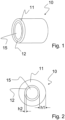
- FIG. 1 The illustrated embodiment shows a catheter tube element 10 according to the invention, preferably for an interventional catheter, with an external, first layer 11 and an internal, second layer 12.
- the catheter tube element according to the invention is designed as a hollow cylinder with an inner lumen 15 formed in the through opening is intended for arranging and preferably receiving a guide wire, not shown.
- the second layer 12 forms the entire inner wall of the catheter tube element.
- the first layer 11 forms the entire outer surface of the catheter tube element 10.
- the first layer 11 and the second layer 12 are firmly connected to one another.
- the second layer 12 can also be arranged only partially, for example in a network or strip structure, on the inside of the first layer 11 and therefore only partially form the inner wall of the catheter tube element.
- the part of the inner wall not formed by the second layer 12 is formed by the layer arranged under the second layer 12.
- the first layer 11 contains one or more plastics from the group PEBA, polyamide and elastomer-modified polyamide.
- the second layer 12 contains and consists entirely of ethylenetetrafluoroethylene (ETFE).
- EFE ethylenetetrafluoroethylene
- the first layer 11 consists entirely of PEBA or entirely of polyamide or entirely of an elastomer-modified polyamide.
- a balloon element can be provided welded to the first layer 11 at a distal end of the catheter tube element.
- the layer thickness h1 of the first layer shown is at least 50 ⁇ m, preferably at least 80 ⁇ m.
- the layer thickness h2 of the second layer 12 is preferably a few micrometers, preferably at least 5 ⁇ m and particularly preferably at least 10 ⁇ m.
- the ratio of the layer thicknesses h1/h2 is at least 3:1, preferably at least 4:1.
- Fig. 2 It can be seen that the first layer 11 and the second layer 12 each have the same layer thickness over the entire cross section.
- the present invention creates a catheter tube element which, on the one hand, can be sterilized by radiation and, on the other hand, has good bending and sliding properties.
- the outer layer of the catheter tube element can be easily welded.
Landscapes
- Health & Medical Sciences (AREA)
- Life Sciences & Earth Sciences (AREA)
- Composite Materials (AREA)
- Materials Engineering (AREA)
- Engineering & Computer Science (AREA)
- Epidemiology (AREA)
- Chemical & Material Sciences (AREA)
- Animal Behavior & Ethology (AREA)
- General Health & Medical Sciences (AREA)
- Public Health (AREA)
- Veterinary Medicine (AREA)
- Materials For Medical Uses (AREA)
- Media Introduction/Drainage Providing Device (AREA)
Description
- Die Erfindung betrifft ein mehrschichtiges Katheterrohrelement, vorzugsweise zur Anordnung eines Führungsdrahtes, mit einer die äußere Schicht bildenden ersten Schicht und mindestens teilweise die innere Schicht bildenden zweiten Schicht. Die Erfindung betrifft ferner ein Verfahren zur Herstellung eines derartigen Katheterrohrelements.
- Als Katheter werden Röhrchen oder Schläuche verschiedenen Durchmessers aus Materialien wie Kunststoff, Latex, Silikon, Metall oder Glas bezeichnet, mit denen Hohlorgane wie Harnblase, Magen, Darm, Gefäße, das Ohr oder das Herz sondiert, entleert, gefüllt oder gespült werden können. So genannte interventionelle Katheter, die für Interventionen, wie z.B. eine perkutane transluminale Angioplastie, verwendet werden, weisen eine Durchgangsöffnung auf, die zur Aufnahme eines Führungsdrahtes bestimmt ist. Zur Erweiterung oder Wiederöffnung eines verengten oder verschlossenen Blutgefäßes wird ein Ballonkatheter, d.h. ein Katheter, der an seinem distalen Ende ein Ballonelement aufweist, entlang des Führungsdrahts eingeführt und an der Stelle des Gefäßes platziert, die geöffnet oder geweitet werden soll.
- Im Folgenden wird als Katheterrohrelement ein Abschnitt eines Katheters bezeichnet, der sich mindestens über einen Teil der Länge des Katheters erstreckt. Vorzugsweise umfasst das Katheterrohrelement auch den Abschnitt eines Ballonkatheters, in dem der Ballon angeordnet ist.
- Für die interventionelle Katheterisierung werden häufig Katheterrohrelemente verwendet, welche zwei übereinander angeordnete Schichten aufweisen, die aneinander befestigt sind, wobei diese Schichten in ihren mechanischen Eigenschaften unterschiedlich beschaffen sind.
- Ein in
EP 0 650 740 B1 beschriebener Katheter weist eine innere Schicht auf, welche die mittig angeordnete Durchgangsöffnung bildet und aus Polyethylen besteht. Die äußere Schicht besteht aus Polyamid und weist an ihrem distalen Ende den Ballon zur Dilatation auf, der an die äußere Polyamidschicht des Katheterrohres geschweißt ist. Derartige Schläuche haben den Nachteil, dass die Verbindung zwischen den Schichten schwach ist, so dass häufig Delaminationsprobleme auftreten. Der Führungsdraht in dem longitudinalen Lumen des Katheters sitzt häufig fest und wird deshalb beim Herausziehen des Ballons durch diesen mitgenommen. Dadurch muss der Führungsdraht für eine erneute Dilatation noch einmal in das Gefäß eingeschoben werden. - In
WO 92/11893 A1 - Die aus
WO 91/17782 A1 - Die
US 2006/0198976 A1 beschreibt einen mehrlumigen Katheter, der mit Hilfe eines Schrumpfschlauches hergestellt wird und der dreidimensionale Muster aufweist. - In der französichen Patentschrift mit der Veröffentlichungsnummer N°
2 444 063 - Weitere bekannte Katheterrohrelemente setzen sich aus einer äußeren Polyamidschicht und einer inneren Schicht aus Polytetrafluorethylen (PTFE) zusammen. Ein derartiges Katheterrohrelement weist sehr gute Gleiteigenschaften auf, ist jedoch nicht strahlensterilisierbar, da PTFE durch die bei der Strahlensterilisierung verwendete ionisierende Strahlung (Röntgen- oder Gammastrahlung, auch Elektronenbeschuss) geschädigt wird.
- Die
EP 1 839 686 A1 Katheter mit einer inneren Katheterschicht, die aus einer Zusammensetzung besteht, die ETFE und PTFE in einem Massenverhältnis von 99:1 bis 45:55 enthält. Weiterhn weisst dieser Katheder eine äußere Harzschicht auf. - Ein Katheder gemäß der
WO 95/15780 - Aus der
WO 2006/039392 A2 ist ein Katheder bekannt, der aus einem Innenrohr und einer um dises Innenrohr herum gebildeten mehrschichtige Hülle besteht. Die mehrschichtige Hülle beinhaltet eine Zwischenschicht, die von einem ersten Polyetherblockamidmaterial gebildet wird und eine von einem anderen zweiten Polyetherblockamid gebildete Außenschicht. Daziwschen kann Verstärkungsmaterial angeordnet sein. - Die Aufgabe der vorliegenden Erfindung besteht demnach darin, ein Katheterrohrelement zu schaffen, welches sehr gute Biegeeigenschaften und Gleiteigenschaften aufweist, an seiner äußeren Oberfläche schweißbar ist sowie eine Strahlensterilisierung ermöglicht.
- Die Aufgabe wird durch ein Katheterrohrelement nach Anspruch 1 gelöst, dessen erste Schicht mindestens ein Kunststoff oder mehrere Kunststoffe aus der Gruppe Polyamid und Elastomer modif ziertes Polyamid wie z.B. Polyether-Block-Amid (PEBA) enthält und dessenzweite Schicht aus Ethylentetrafluorethylen (ETFE)besteht, dadurch gekennzeichnet,
dass das Katheterrohrelement mittels Koextrusion oder mittels eines Tauchverfahrens, das vorzugsweise mehrstufig ist, hergestellt ist. - Der Vorteil des erfindungsgemäßen Katheterelements besteht darin, dass die erste Schicht bestehend aus einem oder mehreren der angegebenen Materialien gut schweißbar ist, so dass ein Ballon auf das Katheterelement geschweißt werden kann. Zudem lässt sich eine gute Verbindung zwischen den Kuns stoffen der ersten Schicht und ETFE erzielen, so dass Delaminationsprobleme nicht auftreten. Die bei dem erfindungsgemä-ßen Katheterelement verwendeten Kunststoffe, insbesondere ETFE, sind außerdem strahlensterilisierbar. Ein weiterer Vorteil des Materials ETFE besteht darin, dass es gute Gleiteigenschaften besitzt, chemikalienbeständig ist und bei Temperaturen bis 150°C eingesetzt werden kann. ETFE ist ein sehr stabiles Fluorpolymer und kann in Schichtdicken bis zu 1000 mm (1 mm) aufgetragen werden. Das Material ist zudem elektrisch sehr gut isolierend und chemisch beständig gegen fast alle Medien. Außerdem ist ETFE im Gegensatz zu PTFE thermoplastisch umformbar.
- Die innere Schicht muss nicht die gesamte Innenfläche des Katheters bedecken. In der einfachsten, vorteilhaftesten Ausführungsform ist das Katheterrohrelement hohlzylinderförmig ausgebildet, so dass der Querschnitt durch einen Kreisring gebildet wird. In weiteren Ausführungsbeispielen kann das Katheterrohrelement auch anders geformt sein, beispielsweise einen Querschnitt in Form eines Ellipsenrings, eines Rechteckrings oder eines anderen Vieleckrings mit abgerundeten Ecken aufweisen. Die durchgehende Öffnung des Katheterrohrelements ist vorzugsweise etwa mittig angeordnet. Ebenfalls möglich ist die Versetzung der durchgehenden Öffnung des Katheterrohrelements etwas aus der Mitte heraus.
- Ebenfalls ein sehr einfacher Aufbau, der zu einem sehr kleinen, vorteilhaften Gesamtdurchmesser des Katheterrohrelements führt, besteht aus genau zwei, fest miteinander verbundenen Schichten. Für eine geeignte Flexibilität des Katheterrohrelements weist die erste Schicht einen Härtegrad zwischen etwa 45 bis etwa 72 Shore D auf. Das Katheterrohrelement ist einfach gestaltet, da die zweite Schicht vollständig aus ETFE besteht.
- Um gute Gleiteigenschaften des Katheterrohrelements zu erreichen, ist es ausreichend, wenn die innen liegende, zweite Schicht nur dünn mit einer Schichtdicke von wenigen Mikrometern (µm) ausgebildet ist und vorzugsweise eine Schichtdicke von mindestens 5 µm, besonders bevorzugt von mindestens 10 µm aufweist. Demgegenüber hat die äußere, erste Schicht in einem bevorzugten Ausführungsbeispiel eine vergleichsweise größere Schichtdicke, vorzugsweise eine Schichtdicke von mindestens 50 µm, besonders bevorzugt eine Schichtdicke von mindestens 80 µm, um eine ausreichende Stabilität des Katheterrohrelements zu gewährleisten. Anders ausgedrückt ist es von Vorteil, wenn das Verhältnis der Schichtdicke der ersten Schicht zur Schichtdicke der zweiten Schicht mindestens 3:1, vorzugsweise mindestens 4:1 beträgt.
- In einem bevorzugten Ausführungsbeispiel sind die Schichtdicken der ersten und der zweiten Schicht über die gesamte Länge des Katheterrohrelements und den Querschnitt etwa gleich gestaltet. In weiteren Ausführungsbeispielen können die Schichtdicken der ersten und/oder der zweiten Schicht über die Länge des Katheterrohrelements bzw. den Querschnitt variieren.
- Im Hinblick auf das Verfahren zur Herstellung eines derartigen Katheterrohrelements wird die oben angegebene Aufgabe durch ein Verfahren gelöst, bei dem in einem Schritt die erste Schicht und die zweite Schicht koextrudiert werden. Dieses Verfahren ist einfach und kostengünstig und erlaubt die Herstellung von Katheterrohrelementen in großtechnischem Maßstab.
- Eine weitere Möglichkeit zur Herstellung eines derartigen Katheterrohrelements besteht darin, dieses mittels eines mehrstufigen Tauchverfahrens zu erzeugen. Hierfür wird eine, den inneren Hohlraum des Katheterrohrelements freihaltende Achse, die vorzugsweise zylinderförmig ist, bereitgestellt. Diese Achse wird anschließend zur Herstellung der ETFE-Schicht (zweite Schicht) einmal oder mehrmals in eine ETFE-Lösung getaucht, um die gewünschte Dicke der ETFE-Schicht zu erhalten. Anschließend wird die mit der ETFE-Schicht versehene Achse in eine Materiallösung getaucht, die das Material der ersten Schicht enthält. Auch dieser Tauchschritt kann gegebenenfalls mehrmals wiederholt werden, um die gewünschte Schichtdicke der ersten Schicht zu erhalten. Die Achse wird nach Beendigung dieses Schrittes entfernt.
- Es zeigen schematisch:
- Fig. 1
- eine perspektivische Seitenansicht eines Ausführungsbeispiels eines erfindungsgemäßen Katheterrohrelements und
- Fig. 2
- eine Ansicht der Stirnseite des Ausführungsbeispiels gemäß
Fig. 1 . - Das in
Fig. 1 dargestellte Ausführungsbeispiel zeigt ein erfindungsgemäßes Katheterrohrelement 10, vorzugsweise für einen interventionellen Katheter, mit einer außen liegenden, ersten Schicht 11 und einer innen liegenden, zweiten Schicht 12. Das erfindungsgemäße Katheterrohrelement ist als Hohlzylinder mit einem in der durchgehenden Öffnung gebildeten inneren Lumen 15 gestaltet, das zur Anordnung und vorzugsweise zur Aufnahme eines nicht dargestellten Führungsdrahts bestimmt ist. Die zweite Schicht 12 bildet die gesamte Innenwand des Katheterrohrelements aus. Die erste Schicht 11 bildet die gesamte äußere Mantelfläche des Katheterrohrelements 10. Die erste Schicht 11 und die zweite Schicht 12 sind fest miteinander verbunden. - In einem weiteren Ausführungsbeispiel kann die zweite Schicht 12 auch lediglich teilweise, beispielsweise in einer Netz- oder Streifenstruktur, auf der Innenseite der ersten Schicht 11 angeordnet sein und deshalb die Innenwand des Katheterrohrelements nur teilweise ausbilden. In diesem Fall wird der nicht durch die zweite Schicht 12 gebildete Teil der Innenwand durch die unter der zweiten Schicht 12 angeordnete Schicht ausgebildet.
- Die erste Schicht 11 enthält einen oder mehrere Kunststoffe aus der Gruppe PEBA, Polyamid und Elastomer modifiziertes Polyamid. Die zweite Schicht 12 enthält und besteht vollständig aus Ethylentetraflurethylen (ETFE). Die erste Schicht 11 besteht in einem bevorzugten Ausführungsbeispiel vollständig aus PEBA oder vollständig aus Polyamid oder vollständig aus einem Elastomer modifizierten Polyamid.
- An einem distalen Ende des Katheterrohrelements kann ein nicht dargestelltes Ballonelement mit der ersten Schicht 11 verschweißt vorgesehen sein.
- Die in
Fig. 2 dargestellte Schichtdicke h1 der ersten Schicht beträgt mindestens 50 µm, vorzugsweise mindestens 80 µm. Die Schichtdicke h2 der zweiten Schicht 12 beträgt vorzugsweise wenige Mikrometer, bevorzugt mindestens 5 µm und besonders bevorzugt mindestens 10 µm. Das Verhältnis der Schichtdicken h1/h2 ist mindestens 3:1, vorzugsweise mindestens 4:1.Fig. 2 ist zu entnehmen, dass die erste Schicht 11 und die zweite Schicht 12 über den gesamten Querschnitt jeweils die gleiche Schichtdicke besitzen. - Mit der vorliegenden Erfindung wird ein Katheterrohrelement geschaffen, das einerseits strahlensterilisierbar und andererseits gute Biege- und Gleiteigenschaften besitzt. Außerdem ist die äußere Schicht des Katheterrohrelements gut schweißbar.
Bezugszeichen: 10 Katheterrohrelement h1 Schichtdicke der ersten Schicht 11 11 erste Schicht h2 Schichtdicke der zweiten Schicht 12 12 zweite Schicht 15 inneres Lumen des Katheterrohrelements 10
Claims (8)
- Katheterrohrelement (10), vorzugsweise zur Anordnung eines Führungsdrahtes, dadurch gekennzeichnet, dass das Katheterrohrelement besteht aus einer die äußere Schicht bildenden ersten Schicht (11) und einer mindestens teilweise die innere Schicht bildenden zweiten Schicht (12), wobei die erste Schicht mindestens einen Kunststoff oder mehrere Kunststoffe aus der Gruppe Polyether-Block-Amid (PEBA), Polyamid und Elastomer modifiziertes Polyamid enthält
dadurch gekennzeichnet, dass das Katheterrohrelement mittels Koextrusion oder mittels eines Tauchverfahrens, das vorzugsweise mehrstufig ist, hergestellt ist und dass die zweite Schicht (12) vollständig aus Ethylentetrafluorethylen besteht. - Katheterrohrelement nach Anspruch 1, dadurch gekennzeichnet, dass das Katheterrohrelement (10) hohlzylinderförmig ausgebildet ist.
- Katheterrohrelement nach einem der Ansprüche 1 bis 2, dadurch gekennzeichnet, dass das Katheterrohrelement (10) aus genau zwei Schichten (11, 12) besteht.
- Katheterrohrelement nach einem der vorhergehenden Ansprüche, dadurch gekennzeichnet, dass die zweite Schicht (12) eine Schichtdicke (h2) von 5 µm, bevorzugt eine Schichtdicke von mindestens 10 µm aufweist.
- Katheterrohrelement nach einem der vorhergehenden Ansprüche, dadurch gekennzeichnet, dass die erste Schicht (11) eine Schichtdicke (h1) von mindestens 50 µm, vorzugsweise von mindestens 80 µm aufweist.
- Katheterrohrelement nach einem der vorhergehenden Ansprüche, dadurch gekennzeichnet, dass das Verhältnis der Schichtdicke (h1) der ersten Schicht (11) zur Schichtdicke (h2) der zweiten Schicht (12) (h1 / h2) mindestens 3:1, vorzugsweise mindestens 4:1 beträgt.
- Katheterrohrelement nach einem der vorhergehenden Ansprüche, dadurch gekennzeichnet, dass die Schichtdicke (h1) der ersten Schicht (11) und die Schichtdicke (h2) der zweiten Schicht (12) über die gesamte Länge des Katheterrohrelements und/oder den gesamten Querschnitt des Katheterrohrelements jeweils im Wesentlichen konstant bleibt.
- Katheterrohrelement nach einem der vorhergehenden Ansprüche, wobei die erste Schicht (11) aus einem Material mit einem Härtegrad zwischen 45 bis 72 Shore D besteht.
Applications Claiming Priority (1)
| Application Number | Priority Date | Filing Date | Title |
|---|---|---|---|
| DE102006062187A DE102006062187A1 (de) | 2006-12-22 | 2006-12-22 | Katheterrohrelement |
Publications (4)
| Publication Number | Publication Date |
|---|---|
| EP1941917A2 EP1941917A2 (de) | 2008-07-09 |
| EP1941917A3 EP1941917A3 (de) | 2010-07-21 |
| EP1941917B1 EP1941917B1 (de) | 2017-04-19 |
| EP1941917B2 true EP1941917B2 (de) | 2024-01-24 |
Family
ID=39427727
Family Applications (1)
| Application Number | Title | Priority Date | Filing Date |
|---|---|---|---|
| EP07023001.6A Active EP1941917B2 (de) | 2006-12-22 | 2007-11-28 | Katheterrohrelement |
Country Status (3)
| Country | Link |
|---|---|
| US (1) | US20080154239A1 (de) |
| EP (1) | EP1941917B2 (de) |
| DE (1) | DE102006062187A1 (de) |
Families Citing this family (2)
| Publication number | Priority date | Publication date | Assignee | Title |
|---|---|---|---|---|
| DE102013221101A1 (de) | 2013-10-17 | 2015-04-23 | Raumedic Ag | Hochdruck-Schlauch mit mehreren Koextrusions-Schichten |
| US9681833B2 (en) | 2014-04-18 | 2017-06-20 | Tekni-Plex, Inc. | Coextruded plastic capillary tube |
Citations (1)
| Publication number | Priority date | Publication date | Assignee | Title |
|---|---|---|---|---|
| EP1839686A1 (de) † | 2005-01-21 | 2007-10-03 | Terumo Kabushiki Kaisha | Katheter und herstellungsverfahren dafür |
Family Cites Families (16)
| Publication number | Priority date | Publication date | Assignee | Title |
|---|---|---|---|---|
| US4266542A (en) * | 1978-12-14 | 1981-05-12 | Baxter Travenol Laboratories, Inc. | EVA Formulation having improved properties |
| US5312356A (en) | 1989-05-22 | 1994-05-17 | Target Therapeutics | Catheter with low-friction distal segment |
| EP0567549B1 (de) | 1991-01-14 | 1998-06-24 | Kontron Instruments, Inc. | Katheter oder zentrales lumen aus dauerhaftem und flexiblem material mit niedrigem knickradius |
| JP3310031B2 (ja) * | 1992-10-23 | 2002-07-29 | テルモ株式会社 | カテーテルチューブ |
| US5961765A (en) * | 1994-09-20 | 1999-10-05 | Schneider (Europe) A. G. | Method of making a catheter |
| ATE184799T1 (de) | 1993-10-27 | 1999-10-15 | Schneider Europ Gmbh | Eingriffskatheter |
| US6146373A (en) * | 1997-10-17 | 2000-11-14 | Micro Therapeutics, Inc. | Catheter system and method for injection of a liquid embolic composition and a solidification agent |
| US6102890A (en) * | 1998-10-23 | 2000-08-15 | Scimed Life Systems, Inc. | Catheter having improved proximal shaft design |
| US6245053B1 (en) * | 1998-11-09 | 2001-06-12 | Medtronic, Inc. | Soft tip guiding catheter and method of fabrication |
| US6508804B2 (en) * | 1999-07-28 | 2003-01-21 | Scimed Life Systems, Inc. | Catheter having continuous lattice and coil reinforcement |
| JP4096556B2 (ja) * | 2000-03-23 | 2008-06-04 | ダイキン工業株式会社 | 多層積層体の製造方法 |
| US20020156459A1 (en) * | 2001-04-20 | 2002-10-24 | Scimed Life Systems, Inc | Microcatheter with improved distal tip and transitions |
| US7488339B2 (en) * | 2002-10-21 | 2009-02-10 | Boston Scientific Scimed, Inc. | Multilayer medical device |
| US7166099B2 (en) * | 2003-08-21 | 2007-01-23 | Boston Scientific Scimed, Inc. | Multilayer medical devices |
| US20050209674A1 (en) * | 2003-09-05 | 2005-09-22 | Kutscher Tuvia D | Balloon assembly (V) |
| US9320831B2 (en) | 2005-03-04 | 2016-04-26 | W. L. Gore & Associates, Inc. | Polymer shrink tubes and novel uses therefor |
-
2006
- 2006-12-22 DE DE102006062187A patent/DE102006062187A1/de not_active Withdrawn
-
2007
- 2007-11-28 EP EP07023001.6A patent/EP1941917B2/de active Active
- 2007-12-21 US US11/963,167 patent/US20080154239A1/en not_active Abandoned
Patent Citations (1)
| Publication number | Priority date | Publication date | Assignee | Title |
|---|---|---|---|---|
| EP1839686A1 (de) † | 2005-01-21 | 2007-10-03 | Terumo Kabushiki Kaisha | Katheter und herstellungsverfahren dafür |
Also Published As
| Publication number | Publication date |
|---|---|
| US20080154239A1 (en) | 2008-06-26 |
| DE102006062187A1 (de) | 2008-06-26 |
| EP1941917B1 (de) | 2017-04-19 |
| EP1941917A3 (de) | 2010-07-21 |
| EP1941917A2 (de) | 2008-07-09 |
Similar Documents
| Publication | Publication Date | Title |
|---|---|---|
| DE69828429T2 (de) | Ballonkatheter sowie herstellungsverfahren dafür | |
| DE69827594T2 (de) | Ballonkatheter mit einem spiralfederförmigen Übergangsbereich | |
| DE69625329T2 (de) | Eingriffkatheter | |
| DE60225565T2 (de) | Katheter und methode zum herstellen eines katheters | |
| DE69629167T2 (de) | Ballonkatheter mit geflochtenem Schaft | |
| DE69321257T2 (de) | Gebogener koaxial-katheter | |
| DE602005004628T2 (de) | Katheter mit einem expandierbaren Körper | |
| DE69217811T2 (de) | Linearer Eversionskatheter mit Innenkörper-Dehnung | |
| DE69918244T2 (de) | Führungskatheter mit weicher Spitze | |
| DE69727238T2 (de) | Führungskatheter mit verbesserter verfolgung des führungsdrahts | |
| DE68922887T2 (de) | Zusammengesetzter Gefässkatheter. | |
| DE60219490T2 (de) | Mikrokatheter mit verbesserter distaler spitze und übergängen | |
| DE3921634C2 (de) | Harnleiterverweilkathetersystem | |
| DE69738235T2 (de) | Hybrider, rohrförmiger katheterführungsdraht | |
| DE60118347T2 (de) | Führungskatheter mit einer gleitfähigen innenbeschichtung | |
| DE69606845T2 (de) | Hochleistungskatheter mit geflochtenem Element | |
| DE69721631T2 (de) | Knickresistenter geflochtener Katheter mit distalen Seitenlöchern | |
| DE69328733T2 (de) | Einlumiger ballonkatheter mit einem wegeventil | |
| EP0079486B1 (de) | Versteifungskern für einen Katheterschlauch | |
| DE60105230T2 (de) | Ballonkatheter mit schwimmender Versteifung | |
| DE69532521T2 (de) | Katheter | |
| DE69529806T2 (de) | Katheter mit Mehrschichtbereich | |
| DE69833332T2 (de) | Geflochtener hochleistungskatheter mit weicher spitze | |
| DE69124395T2 (de) | Führungsdraht zum durchqueren von okklusionen in blutgefässen | |
| DE69821956T2 (de) | Abgabekatheter für periphere Blutgefässe |
Legal Events
| Date | Code | Title | Description |
|---|---|---|---|
| PUAI | Public reference made under article 153(3) epc to a published international application that has entered the european phase |
Free format text: ORIGINAL CODE: 0009012 |
|
| AK | Designated contracting states |
Kind code of ref document: A2 Designated state(s): AT BE BG CH CY CZ DE DK EE ES FI FR GB GR HU IE IS IT LI LT LU LV MC MT NL PL PT RO SE SI SK TR |
|
| AX | Request for extension of the european patent |
Extension state: AL BA HR MK RS |
|
| PUAL | Search report despatched |
Free format text: ORIGINAL CODE: 0009013 |
|
| AK | Designated contracting states |
Kind code of ref document: A3 Designated state(s): AT BE BG CH CY CZ DE DK EE ES FI FR GB GR HU IE IS IT LI LT LU LV MC MT NL PL PT RO SE SI SK TR |
|
| AX | Request for extension of the european patent |
Extension state: AL BA HR MK RS |
|
| 17P | Request for examination filed |
Effective date: 20110113 |
|
| AKX | Designation fees paid |
Designated state(s): CH DE FR GB IE LI |
|
| RBV | Designated contracting states (corrected) |
Designated state(s): CH DE FR GB IE LI |
|
| 17Q | First examination report despatched |
Effective date: 20111206 |
|
| GRAP | Despatch of communication of intention to grant a patent |
Free format text: ORIGINAL CODE: EPIDOSNIGR1 |
|
| STAA | Information on the status of an ep patent application or granted ep patent |
Free format text: STATUS: GRANT OF PATENT IS INTENDED |
|
| INTG | Intention to grant announced |
Effective date: 20161214 |
|
| GRAS | Grant fee paid |
Free format text: ORIGINAL CODE: EPIDOSNIGR3 |
|
| GRAA | (expected) grant |
Free format text: ORIGINAL CODE: 0009210 |
|
| STAA | Information on the status of an ep patent application or granted ep patent |
Free format text: STATUS: THE PATENT HAS BEEN GRANTED |
|
| AK | Designated contracting states |
Kind code of ref document: B1 Designated state(s): CH DE FR GB IE LI |
|
| REG | Reference to a national code |
Ref country code: GB Ref legal event code: FG4D Free format text: NOT ENGLISH |
|
| REG | Reference to a national code |
Ref country code: CH Ref legal event code: EP |
|
| REG | Reference to a national code |
Ref country code: IE Ref legal event code: FG4D Free format text: LANGUAGE OF EP DOCUMENT: GERMAN |
|
| REG | Reference to a national code |
Ref country code: DE Ref legal event code: R096 Ref document number: 502007015591 Country of ref document: DE |
|
| REG | Reference to a national code |
Ref country code: DE Ref legal event code: R026 Ref document number: 502007015591 Country of ref document: DE |
|
| PLBI | Opposition filed |
Free format text: ORIGINAL CODE: 0009260 |
|
| PLAX | Notice of opposition and request to file observation + time limit sent |
Free format text: ORIGINAL CODE: EPIDOSNOBS2 |
|
| 26 | Opposition filed |
Opponent name: EVONIK DEGUSSA GMBH Effective date: 20180119 |
|
| REG | Reference to a national code |
Ref country code: DE Ref legal event code: R082 Ref document number: 502007015591 Country of ref document: DE Ref country code: DE Ref legal event code: R081 Ref document number: 502007015591 Country of ref document: DE Owner name: BIOTRONIK AG, CH Free format text: FORMER OWNER: BIOTRONIK VI PATENT AG, BAAR, CH |
|
| RAP2 | Party data changed (patent owner data changed or rights of a patent transferred) |
Owner name: BIOTRONIK AG |
|
| PLBB | Reply of patent proprietor to notice(s) of opposition received |
Free format text: ORIGINAL CODE: EPIDOSNOBS3 |
|
| REG | Reference to a national code |
Ref country code: GB Ref legal event code: 732E Free format text: REGISTERED BETWEEN 20180719 AND 20180725 |
|
| REG | Reference to a national code |
Ref country code: FR Ref legal event code: ST Effective date: 20180731 |
|
| PG25 | Lapsed in a contracting state [announced via postgrant information from national office to epo] |
Ref country code: FR Free format text: LAPSE BECAUSE OF NON-PAYMENT OF DUE FEES Effective date: 20171130 |
|
| APBM | Appeal reference recorded |
Free format text: ORIGINAL CODE: EPIDOSNREFNO |
|
| APBP | Date of receipt of notice of appeal recorded |
Free format text: ORIGINAL CODE: EPIDOSNNOA2O |
|
| APAH | Appeal reference modified |
Free format text: ORIGINAL CODE: EPIDOSCREFNO |
|
| APBM | Appeal reference recorded |
Free format text: ORIGINAL CODE: EPIDOSNREFNO |
|
| APBP | Date of receipt of notice of appeal recorded |
Free format text: ORIGINAL CODE: EPIDOSNNOA2O |
|
| APBQ | Date of receipt of statement of grounds of appeal recorded |
Free format text: ORIGINAL CODE: EPIDOSNNOA3O |
|
| PLAB | Opposition data, opponent's data or that of the opponent's representative modified |
Free format text: ORIGINAL CODE: 0009299OPPO |
|
| R26 | Opposition filed (corrected) |
Opponent name: EVONIK OPERATIONS GMBH Effective date: 20180119 |
|
| APBU | Appeal procedure closed |
Free format text: ORIGINAL CODE: EPIDOSNNOA9O |
|
| PLAY | Examination report in opposition despatched + time limit |
Free format text: ORIGINAL CODE: EPIDOSNORE2 |
|
| PLBC | Reply to examination report in opposition received |
Free format text: ORIGINAL CODE: EPIDOSNORE3 |
|
| PLAY | Examination report in opposition despatched + time limit |
Free format text: ORIGINAL CODE: EPIDOSNORE2 |
|
| PGFP | Annual fee paid to national office [announced via postgrant information from national office to epo] |
Ref country code: IE Payment date: 20221122 Year of fee payment: 16 |
|
| P01 | Opt-out of the competence of the unified patent court (upc) registered |
Effective date: 20230605 |
|
| PUAH | Patent maintained in amended form |
Free format text: ORIGINAL CODE: 0009272 |
|
| STAA | Information on the status of an ep patent application or granted ep patent |
Free format text: STATUS: PATENT MAINTAINED AS AMENDED |
|
| PGFP | Annual fee paid to national office [announced via postgrant information from national office to epo] |
Ref country code: GB Payment date: 20231123 Year of fee payment: 17 |
|
| 27A | Patent maintained in amended form |
Effective date: 20240124 |
|
| AK | Designated contracting states |
Kind code of ref document: B2 Designated state(s): CH DE FR GB IE LI |
|
| REG | Reference to a national code |
Ref country code: DE Ref legal event code: R102 Ref document number: 502007015591 Country of ref document: DE |
|
| PGFP | Annual fee paid to national office [announced via postgrant information from national office to epo] |
Ref country code: DE Payment date: 20231120 Year of fee payment: 17 Ref country code: CH Payment date: 20231201 Year of fee payment: 17 |
|
| REG | Reference to a national code |
Ref country code: IE Ref legal event code: MM4A |
|
| PG25 | Lapsed in a contracting state [announced via postgrant information from national office to epo] |
Ref country code: IE Free format text: LAPSE BECAUSE OF NON-PAYMENT OF DUE FEES Effective date: 20231128 |