EP1941255B1 - Modulare vorrichtung zur analyse einer biologischen flüssigkeit, wie z.b. blut - Google Patents
Modulare vorrichtung zur analyse einer biologischen flüssigkeit, wie z.b. blut Download PDFInfo
- Publication number
- EP1941255B1 EP1941255B1 EP06831193A EP06831193A EP1941255B1 EP 1941255 B1 EP1941255 B1 EP 1941255B1 EP 06831193 A EP06831193 A EP 06831193A EP 06831193 A EP06831193 A EP 06831193A EP 1941255 B1 EP1941255 B1 EP 1941255B1
- Authority
- EP
- European Patent Office
- Prior art keywords
- functional module
- preparation
- injection
- modular device
- functional
- Prior art date
- Legal status (The legal status is an assumption and is not a legal conclusion. Google has not performed a legal analysis and makes no representation as to the accuracy of the status listed.)
- Not-in-force
Links
- 239000013060 biological fluid Substances 0.000 title claims abstract description 12
- 210000004369 blood Anatomy 0.000 title description 16
- 239000008280 blood Substances 0.000 title description 16
- 238000002360 preparation method Methods 0.000 claims abstract description 102
- 238000002347 injection Methods 0.000 claims abstract description 85
- 239000007924 injection Substances 0.000 claims abstract description 85
- 239000012895 dilution Substances 0.000 claims abstract description 67
- 238000010790 dilution Methods 0.000 claims abstract description 67
- 238000004458 analytical method Methods 0.000 claims abstract description 53
- 239000012530 fluid Substances 0.000 claims abstract description 39
- 239000003153 chemical reaction reagent Substances 0.000 claims description 20
- 238000000034 method Methods 0.000 claims description 18
- 238000005070 sampling Methods 0.000 claims description 17
- 239000002699 waste material Substances 0.000 claims description 17
- 238000004519 manufacturing process Methods 0.000 claims description 15
- 230000000295 complement effect Effects 0.000 claims description 4
- 238000005259 measurement Methods 0.000 description 36
- 210000004027 cell Anatomy 0.000 description 23
- 230000003287 optical effect Effects 0.000 description 18
- 239000000203 mixture Substances 0.000 description 9
- 238000005194 fractionation Methods 0.000 description 8
- 238000012423 maintenance Methods 0.000 description 8
- 238000005253 cladding Methods 0.000 description 6
- 230000008569 process Effects 0.000 description 6
- NIXOWILDQLNWCW-UHFFFAOYSA-N acrylic acid group Chemical group C(C=C)(=O)O NIXOWILDQLNWCW-UHFFFAOYSA-N 0.000 description 5
- 210000003743 erythrocyte Anatomy 0.000 description 5
- 238000011534 incubation Methods 0.000 description 5
- 210000000265 leukocyte Anatomy 0.000 description 5
- 238000002156 mixing Methods 0.000 description 4
- 238000012360 testing method Methods 0.000 description 4
- 230000008901 benefit Effects 0.000 description 3
- 230000007423 decrease Effects 0.000 description 3
- 238000010586 diagram Methods 0.000 description 3
- 230000006872 improvement Effects 0.000 description 3
- 238000011068 loading method Methods 0.000 description 3
- 238000002835 absorbance Methods 0.000 description 2
- 238000004820 blood count Methods 0.000 description 2
- 238000004140 cleaning Methods 0.000 description 2
- 238000013461 design Methods 0.000 description 2
- 239000003085 diluting agent Substances 0.000 description 2
- 230000000694 effects Effects 0.000 description 2
- 238000005516 engineering process Methods 0.000 description 2
- 210000003714 granulocyte Anatomy 0.000 description 2
- 230000002489 hematologic effect Effects 0.000 description 2
- 238000002847 impedance measurement Methods 0.000 description 2
- 239000007788 liquid Substances 0.000 description 2
- 206010003830 Automatism Diseases 0.000 description 1
- 102000004190 Enzymes Human genes 0.000 description 1
- 108090000790 Enzymes Proteins 0.000 description 1
- 102000001554 Hemoglobins Human genes 0.000 description 1
- 108010054147 Hemoglobins Proteins 0.000 description 1
- FAPWRFPIFSIZLT-UHFFFAOYSA-M Sodium chloride Chemical compound [Na+].[Cl-] FAPWRFPIFSIZLT-UHFFFAOYSA-M 0.000 description 1
- 230000006978 adaptation Effects 0.000 description 1
- 210000003651 basophil Anatomy 0.000 description 1
- 238000012742 biochemical analysis Methods 0.000 description 1
- 238000010261 blood fractionation Methods 0.000 description 1
- 210000001772 blood platelet Anatomy 0.000 description 1
- 230000001413 cellular effect Effects 0.000 description 1
- 230000008859 change Effects 0.000 description 1
- 238000011161 development Methods 0.000 description 1
- 230000004069 differentiation Effects 0.000 description 1
- 210000003979 eosinophil Anatomy 0.000 description 1
- 238000010438 heat treatment Methods 0.000 description 1
- 239000012212 insulator Substances 0.000 description 1
- 238000002372 labelling Methods 0.000 description 1
- 210000004698 lymphocyte Anatomy 0.000 description 1
- 238000000691 measurement method Methods 0.000 description 1
- 239000002184 metal Substances 0.000 description 1
- 210000001616 monocyte Anatomy 0.000 description 1
- 210000000440 neutrophil Anatomy 0.000 description 1
- 238000012545 processing Methods 0.000 description 1
- 239000000376 reactant Substances 0.000 description 1
- 230000009467 reduction Effects 0.000 description 1
- 230000002441 reversible effect Effects 0.000 description 1
- 239000000243 solution Substances 0.000 description 1
- 238000010186 staining Methods 0.000 description 1
- 239000012899 standard injection Substances 0.000 description 1
Images


Classifications
-
- G—PHYSICS
- G01—MEASURING; TESTING
- G01N—INVESTIGATING OR ANALYSING MATERIALS BY DETERMINING THEIR CHEMICAL OR PHYSICAL PROPERTIES
- G01N15/00—Investigating characteristics of particles; Investigating permeability, pore-volume or surface-area of porous materials
- G01N15/10—Investigating individual particles
- G01N15/14—Optical investigation techniques, e.g. flow cytometry
- G01N15/1404—Handling flow, e.g. hydrodynamic focusing
-
- G—PHYSICS
- G01—MEASURING; TESTING
- G01N—INVESTIGATING OR ANALYSING MATERIALS BY DETERMINING THEIR CHEMICAL OR PHYSICAL PROPERTIES
- G01N1/00—Sampling; Preparing specimens for investigation
- G01N1/28—Preparing specimens for investigation including physical details of (bio-)chemical methods covered elsewhere, e.g. G01N33/50, C12Q
- G01N1/38—Diluting, dispersing or mixing samples
-
- G—PHYSICS
- G01—MEASURING; TESTING
- G01N—INVESTIGATING OR ANALYSING MATERIALS BY DETERMINING THEIR CHEMICAL OR PHYSICAL PROPERTIES
- G01N35/00—Automatic analysis not limited to methods or materials provided for in any single one of groups G01N1/00 - G01N33/00; Handling materials therefor
- G01N2035/00178—Special arrangements of analysers
- G01N2035/00326—Analysers with modular structure
Definitions
- the present invention relates to the general field of systems for the analysis of a biological fluid such as blood, plasma, etc.
- the invention applies to analyzers of blood samples, also called hematology analyzers.
- the main examination in hematology is the counting of cellular elements contained in the blood.
- the main elements are red blood cells, white blood cells and platelets. It is a valuable diagnostic tool for the doctor or veterinarian.
- the counts are most often carried out in private or hospital laboratories for medical analyzes by qualified technicians. In some countries, doctors can also perform tests in their practice.
- the number of daily countings is extremely variable and can range from a few tests per day in a doctor's office to several thousand tests in a very large private or hospital laboratory.
- the analysis systems are characterized by their rate, the number of hematological parameters rendered and their degree of automatism.
- the rate varies between 60 and 120 tests per hour, the operator has more or fewer operations to perform manually and the parameters are rendered more or less numerous: limited to the blood count or extended, in particular, to the differentiation of sub-families of white blood cells.
- Hydraulic circuits of the "manifold" type have been known for a long time.
- the use of such circuits can significantly reduce the number of pipes needed to connect hydraulic components. This decrease increases reliability of the device and therefore to reduce the maintenance. It can also be noted that the use of manifolds reduces the risk of leakage and increase the resistance of the fluid circuits to reactants.
- this support includes at least two plates in which are engraved circuits that define pipes when the plates are assembled side by side.
- the hydraulic components then used are in particular dilution vessels, diaphragm valves controlled by pressure / vacuum switching, syringes, sampling valves, diaphragm pumps, pneumatic valves for controlling the diaphragm valves. integrated etc.
- the patent US 5,788,927 describes such an embodiment.
- the acrylic support described in this document is intended to allow the realization of a very specific group of functions and is therefore specific to a particular system.
- the support made using a relatively large number of plates assembled side by side, integrates not only pipes but also dilution tanks, diaphragm valves, controlled by a pressure / vacuum switching.
- the holder also serves as a support for a sampling valve, diaphragm pumps, pneumatic valves for controlling the integrated diaphragm valves and heating.
- the patent FR 2 862 387 from C2 Diagnostics also describes such a system in the form of a syringe block with a plastic support to prepare, inject and dose a fluid to be analyzed.
- the syringe block is self-contained and operates with a pump air.
- Solenoid valves are further integrated in the support which can be connected to the optical bench via the hydraulic circuits carried by the support.
- this syringe block does not offer manufacturing flexibility.
- the device proposed in the document US 5,788,927 the device integrates a plurality of predetermined and fixed functions in the same block. To add or modify functions, it is necessary to design a new syringe block.
- FR2841653 also describes a modular device intended to be implemented in a biological fluid analysis system, said modular device comprising functional modules each comprising a support for supporting hydraulic components
- the main object of the present invention is to overcome such drawbacks by proposing a modular device intended to be implemented in a system for analyzing a biological fluid, said modular device comprising functional modules each comprising a support for supporting components.
- said support including at least two plates in which are engraved circuits that define channels when the two plates are assembled side by side, said modular device being such that said functional modules comprise at least a first functional module preparation for preparing the fluid to be analyzed which supports at least one dilution vessel and a second injection functional module for injecting, to an analysis unit, the fluid prepared in said dilution vessel, said first and second modules being connected between they, the device being further such that the support of the m Injection functional module is fixed substantially perpendicularly to the support of the preparation functional module by one of the edges of the periphery of the two plates assembled side by side of said injection functional module.
- preparation is intended to mean the preparation of a sample of the fluid to be analyzed, in particular the dilution steps with a diluent, mixing with a reagent (s), addition of antibodies, enzyme (s) or dye (s). These steps are traditionally done using at least one dilution tank, also called mixing tank.
- injection refers to the steps of sampling in a dilution and injection vessel in an analysis unit in order to analyze the fluid.
- the preparation and the injection of the biological fluid to be analyzed are carried out using different functional modules.
- the functions common to a range of systems can thus be implemented in a given functional module, independently of other functions that may be different depending on the level in the range.
- the positioning of the preparation module perpendicularly to the injection module (s) makes it possible to reduce the bulk of the modular device and therefore of the analysis system while facilitating the modular nature of the system since, for example, several injection functional modules can easily be placed in parallel on the preparation module without increasing the overall parallelepipedal size of the system. It then becomes possible to increase the rate of the analysis system without increasing the overall size.
- This arrangement makes it possible to have short path paths for the fluids, thus reducing the volumes of reagents and samples required.
- the functional preparation and injection modules are connected together without using a pipe.
- pipe a tubular element, generally made of plastic, extending out of the functional modules and therefore distinct from the pipes present in the supports of these functional modules.
- At least one orifice passing through one of the support plates of the preparation functional module is provided for the connection of the injection functional module perpendicularly to this plate.
- At least one orifice is then provided on the periphery edge of the injection functional module for connection to the through orifice of the preparation functional module.
- a simple and easy connection without pipe is then possible by adjusting the through hole of the preparation functional module with the orifice on the edge of the injection module.
- At least one functional module is such that the hydraulic components are fixed outside said support.
- the hydraulic components are, for example, selected from the following components: valves, syringes, dilution vessels.
- fixed is intended to mean a direct and reversible mechanical connection between the supports of two functional modules or between a hydraulic component and the support of a functional module.
- the hydraulic components being, advantageously according to the invention, fixed outside the functional modules and, preferably, without using pipes, it is possible to standardize them in a unitary form.
- the same model of syringes can be adapted for several systems.
- the acrylic supports preferably do not include components such as valves, syringes or dilution chambers in order to allow the realization of a predetermined and precise group of functions, as is the case in the prior art. .
- the hydraulic components are advantageously molded. They can however also be machined.
- hydraulic components created have fasteners and connection interfaces which make them interchangeable.
- the number of hydraulic components fixed on the preparation functional module can therefore be variable depending on the level of the system in the range.
- the modular device includes at least one functional module of preparation comprising a plurality of connection interfaces for the direct and parallel connection of a plurality of functional modules each having a connection interface complementary to those of the preparation functional module, each connection interface being connected to at least one pipe network inside the functional module of preparation.
- the acrylic supports as employed according to the invention are used as rigid supports for hydraulic components and a plurality of functional modules with the function of connecting them together by pipes.
- the supports forming the modules are rigid, they play the mechanical role of support. This is a significant advantage since they avoid the use of structures dedicated to support the various components of the analysis system as is the case today.
- the invention makes it possible moreover to manufacture analysis systems of different range levels by multiplying the analytical rate and this, starting from the same base of functional modules.
- connection interfaces are advantageously identical while allowing the connection of various functional modules, but they may equally well have distinct characteristics and adapted to the singularities of each of the types of functional modules.
- the preparation functional module comprises a reagent fluid inlet orifice intended to be introduced into a dilution vessel and a waste outlet orifice, this waste outlet orifice being unique for said device modular.
- the functional modules connected to the preparation module are advantageously connected so that the waste is centralized in the preparation module and discharged through a single outlet for the modular device.
- waste is defined as meaning tank cleaning residues, residual dilutions or mixtures, dilutions or mixtures injected into the measuring means and those present in the pipes.
- the invention also relates to a functional module of useful preparation in a modular device according to the invention comprising a support for supporting hydraulic components, said support including at least two plates in which are engraved circuits that allow to define pipes when the two plates are assembled side by side, said preparation functional module supporting at least one dilution tank and being able to be connected to a second so-called injection functional module for performing the injection, to an analysis unit, of the prepared fluid in said dilution vessel.
- such a preparation module includes a plurality of identical connection interfaces intended for the direct and parallel connection of a plurality of functional modules, including at least one injection functional module, each having a complementary connection interface. those of said preparation functional module, each connection interface being connected to at least one pipe network inside said preparation functional module.
- the preparation functional module includes a reagent fluid inlet port for introduction into a dilution vessel and a waste outlet port, said waste outlet port being unique to said device modular.
- the invention also relates to an injection module useful in a modular device according to the invention comprising a support for supporting hydraulic components, said support including at least two plates in which are engraved circuits that define the pipes when the two plates are assembled side by side, said injection functional module being able to be connected to a so-called preparation functional module supporting at least one dilution vessel in order to perform the injection, to an analysis unit, of the fluid prepared in said vessel dilution.
- the invention finally relates to a method for producing a system for analyzing a biological fluid including a step of constructing a modular device according to which at least a first functional module for preparing the fluid to be analyzed is connected to a second functional module. injection of the prepared fluid to an analysis unit, said modules comprising a support for supporting components hydraulic, said support including at least two plates in which are engraved circuits that define the pipes when the two plates are assembled side by side.
- the invention finally relates to the use of at least one functional module as presented above in the manufacture of a system for analyzing a biological fluid.
- the figure 1 is a perspective view of a modular device 100 according to the invention.
- a modular device has at least one preparation functional module 101, on which can be connected one or more standard functional modules including at least one injection functional module 102.
- Each of these functional modules includes at least two plates, respectively 101 ', 101 "and 102', 102", forming the supports.
- On the inner face of each of the two pairs of plates are etched circuits. These circuits are symmetrical so that when the plates are assembled in pairs side by side as shown on the figure 1 , they define ducts inside the support formed by the plates, these pipes for connecting hydraulic components to each other.
- This figure shows the principle of the invention which consists in implementing the main functions of an analysis system, which are the preparation and injection of the fluid to be analyzed, on separate functional modules 101 and 102. It will be seen in the following that ensures the modular nature of the device since we can design a range of different complexity and capacity systems with a limited number of parts.
- each functional module has various hydraulic components fixed on the outer faces of the plates.
- the preparation functional module 101 comprises the means necessary for the dilutions, and this, depending on the level of range in which the modular device is intended to operate.
- the hydraulic components necessary for the preparation of the dilutions comprise, at least, a dilution vessel 103, a valve 104 and a syringe 105, necessary elements in particular for assaying the reagents. These hydraulic components are fixed outside the support of the module 101. In known manner, a motorization "step by step” actuating the syringes 105 allows to vary the speeds and volumes while maintaining a good accuracy.
- connection interfaces 106 for connecting the hydraulic components.
- connection interface is understood to mean an interface, generally consisting of orifices, allowing a pipeless connection of two functional modules or of a functional module and of a hydraulic component.
- a connection interface 106 preferably includes at least one fluid inlet port and one fluid outlet port. These orifices are advantageously through holes made on one of the plates of the support of the functional module.
- the ducts etched on the plates constituting the preparation functional module 101 make it possible to connect the connection interfaces and therefore, in particular, the different hydraulic components to each other.
- Connection interfaces not visible on the figure 1 since they are arranged on the face where the injection functional module is connected, they are dedicated to the connection of the functional modules, in particular of an injection functional module 102.
- connection interfaces are complementary to each other. those represented on the figure 6 for an injection module.
- Their shape is advantageously identical to that of the interfaces represented on the figure 6 with the difference that they are made perpendicularly to the faces of the functional module preparation.
- the preparation functional module 101 is provided with connectors 108 that can be used to connect the preparation functional module with the aid of pipes to a functional module or to a hydraulic component.
- connection of the preparation functional module 101 with the injection functional module 102 using pipes and connectors 108.
- the size of the preparation functional module 101 associated with a greater or lesser number of hydraulic components and functional modules connected to it will determine the size of the analysis system, its rate, possibly its automation and, therefore, its level in a given range of systems.
- the number of possible dilutions is very related to the positioning of the system in the range.
- An input device The range can often be satisfied with a single dilution performed with a diluent while a high-end system giving more hematological parameters and faster will require several, made with specific reagents, generally around four.
- the number of dilutions can vary significantly and blood fractionation is not always necessary.
- the principle of the invention makes it possible to leave the blood collection and fractioning means outside this functional module of preparation, either in the form of hydraulic components fixed on the external face of the plates, or in the form of specific functional modules. also fixed on the outer face of the plates.
- a sampling valve as a hydraulic component fixed on the preparation functional module or as a functional module comprising a manifold support supporting the sampling valve, this support being intended to be fixed on the preparation functional module.
- This aspect of the externality of the functions in the form of hydraulic component (s) or functional module (s) is particularly interesting because it makes it possible to build a system of analysis à la carte according in particular to the requested rate, the desired automation and the parameters to be analyzed.
- a preparation functional module equipped according to the invention, has well-defined functions that are separate from those of the functional modules to which it is connected.
- the invention makes it possible to subsequently connect a variable number of functional modules to constitute a system of a particular level in a range of systems. This is illustrated in Figures 1 and 2 .
- Figures 1 and 2 illustrate the modular character of a modular device according to the invention.
- a same preparation functional module 101 which can be more or less equipped by replacing in particular the syringes and / or valves by "straps" and using syringes of different diameters compatible with each other and by connecting a variable number of functional modules, here injection modules 102.
- the figure 1 illustrates an entry-level device.
- the preparation functional module 101 is equipped with four dilution vessels 103, This module may contain only one dilution vessel and a small number of valves and syringes.
- the preparation functional module 101 is equipped with a single injection functional module 102.
- the measurements are performed sequentially from one or more dilutions. Typically, a measurement will be made for red blood cells followed by one or two measurements relating to white blood cells.
- Such a modular device is suitable for entry-level systems for laboratories that do not need a high analytical rate. It would also be possible to produce a more compact specific preparation functional module that would only present the part necessary for the connection of a single injection functional module.
- the figure 2 illustrates a modular device for use in a high-end analysis system.
- the preparation functional module 201 is equipped with the same hydraulic components as the functional module for preparing the figure 1 but in larger numbers. It is furthermore equipped with three injection functional modules 202a, 202b, 202c connected in parallel and making it possible to carry out three series of simultaneous measurements from the dilutions carried out in the six dilution vessels 203.
- Such a modular device 200 is adapted to systems with a high analytical rate.
- the invention is not limited to the two configurations presented on the Figures 1 and 2 , the number of functional module connection interfaces can be increased, one or more functional modules or hydraulic components for fractionation, measurement, etc. can be connected and fixed to the preparation functional module. It is also noted that the preparation functional module may be a single module more or less equipped or have specific characteristics for each level of the range, for example by being more compact, the injection module remaining the same. This does not remove the modular nature of the analysis systems made with a modular device according to the invention. Several preparation modules adapted to each level of a range can thus be advantageously envisaged.
- the number of vats can vary from one to six vats.
- the choice of the number of tanks is made according to the so-called incubation times required to perform the targeted analyzes, the desired rate, the number of parameters analyzed ...
- the incubation time is typically from ten to fifteen seconds and it may therefore be necessary, in a device according to the invention, to respect a time shift in the analysis cycle in order to take it into account. Thus some tanks may not be used after a while while others will continue to be exploited.
- the advantage of having a plurality of tanks is to be able to optimize the use of the tanks in particular according to these incubation times. Indeed, two dilution tanks allow to perform the same analyzes as four tanks, but sequentially and therefore, more slowly.
- the use of the dilution tanks is generally carried out using software controlling the operation of the analysis system. With a good use of the tanks, the rate can be increased significantly.
- the parameters analyzed are, for example, in addition to the count of red blood cells, the number of monocytes, lymphocytes, granulocytes. In this case, only one tank is sufficient. When the analyzes of the amount of neutrophils, basophils and eosinophils in the granulocytes are added, it is necessary to use at least two tanks.
- the tanks are brought closer to the measuring means and, as a general rule, an analysis system obtained with a modular device according to the invention is compact, the quantity of waste is reduced as well as the volumes of reagents and sampling required. This responds well to the concerns of economy of reagents, limitation of sampling and reduction of waste encountered in the field of the analysis of biological fluids.
- the analysis of a fluid for example blood, is a multi-step process that will be carried out successively and independently successively by the preparation functional module, the injection functional module and other modules. functionalities that will be connected to it.
- the combined operation of the different functional modules is detailed below.
- the first step of the analysis is to mix a portion of the blood contained in the patient's tube with a reagent.
- This operation called dilution, is necessary if only to adapt the concentration of cells to the analysis unit used and prepare them specifically according to the measurement to be performed next. It is also used to destroy a specific family of cells, for example red blood cells, to leave only the white blood cells and thus be better able to count or differentiate them by sub-families or to color the nucleus of the cells or to mark them with specific antibodies.
- a first known fractionation method consists in using a sampling valve. The blood is sucked through the sampling valve and fills loops whose volume is predetermined. The sampling valve is then switched so that the blood contained in each loop can be pushed into the different dilution vessels with the corresponding reagents.
- a second fractionation process described in the patent FR 2,770,299 consists in pushing blood fractions contained in a needle into a reagent stream above each dilution vessel.
- blends in dilution tanks must be very accurate.
- the most used dosing element for reagents is the syringe whose volume is adjusted to the dosage to be made.
- the preparation functional module supports the hydraulic components, syringes, valves, vessels and hydraulic connecting circuits for carrying out the dilution (s) after fractionation.
- this step is performed in the preparation functional module independently of the other steps.
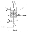
- the figure 3 illustrates the operation of a preparation functional module 301 according to the invention.
- the preparation functional module 301 includes a dilution vessel 303.
- a sample taken arrives, either pushed by a reagent through a line 321 of the preparation functional module 301, or by a sampling needle 322 according to the fractionation method chosen.
- the reagent arrives, meanwhile, through line 321 either following the sample to be analyzed that it grows in the dilution vessel, or alone still according to the fractionation method chosen.
- the dilution vessel is advantageously provided with means for sending air into the mixture obtained in the dilution vessel through a pipe 329 and a valve 328. .
- the mixture or dilution 323 obtained is optionally left for a certain incubation time in the tank so as to respect the kinetics of reaction.
- the dilution vessel 303 is connected to a pipe 324 leading to an injection functional module 302 connected to the preparation functional module 301.
- the mixture 323 is withdrawn by the functional module of FIG. injection 302 as detailed below.
- the remainder of the non-withdrawn mixture is drained and evacuated via a pipe 325 connected through a valve 327 to a waste outlet port 326 which is advantageously unique for the modular device in which the preparation functional module 301 is implemented.
- the next step is the injection of the fluid to be analyzed into an analysis unit, a general term that includes the counting of the cells.
- An analysis unit is preferably a functional measurement module made according to the principles of the invention but may also be a measurement device connected to the modular device according to the invention by pipes.
- the two main known measurement methods are impedance variation measurement or optical process measurement.
- the impedance variation measuring method known by the name COULTER method of the name of its inventor and described in the patent US 3,259,842 issued on July 05, 1966 consists in mixing the globules in a saline solution and then aspirating them through a calibrated orifice of small size, generally between 50 and 100 ⁇ m in diameter; in which circulates an electric current.
- a calibrated orifice of small size, generally between 50 and 100 ⁇ m in diameter; in which circulates an electric current.
- Each globule which passes through the orifice behaves like an insulator and modifies the electric current thus generating a sequence of pulses proportional to the volume of the globules and able to be counted and measured.
- This method can be implemented directly on a dilution vessel as fixed on the functional module of preparation according to the invention or in a measurement unit to which a dilution is injected.
- An important improvement of the process consists in centering the cells in the orifice using a fluid also called sheath fluid.
- the cladding method makes it possible to center the path of the cells during their passage through the measurement orifice. This improvement has the effect of limiting the effects of doubling the cells related to the concentration of the mixture and the small relative size of the cells relative to the diameter of the measuring orifice. The quality of the electrical signal is improved and allows better subsequent processing by electronics.
- the method of centering the cells in a means of measurement by a cladding fluid also referred to as hydraulic focusing of the cells, is obligatory in the case of measurements carried out by only optical means and constitutes a significant improvement in the case of impedance measurements. .
- it requires additional hydraulic means, therefore an additional cost, and this is generally a brake for its application in entry-level systems.
- the additional cost can be offset by a production in greater quantity related to the generalization of the hydraulic focusing for all the systems of a range.
- This generalization also makes it possible to have a level of quality of the analyzes constant whatever the level of the system in the range.
- the method of measurement by an optical method is to circulate cells, previously centered in an optical capillary by a cladding fluid, in front of a light source focused on the cells.
- the counts and measurements can be made by exploiting the absorbance of the cell, its light diffraction power at different angles or its fluorescence after specific staining or labeling with antibodies.
- the injection functional module 402 gathers various hydraulic components fixed on the outside of the plates forming the injection functional module 402 in order to be able to inject the fluid to be analyzed from a dilution tank of a functional module. of preparation connected by a connection interface 410 comprising orifices 411a, 411b, 411c, 411d placed on the non-visible wafer of the injection functional module 402 to a cell counting analysis unit connected to connectors 433a, 433b, 433c, 433d.
- these connectors are the orifices of a connection interface within the meaning of the invention.
- Motors 407a and 407b are connected to the syringes by stirrups 413a and 413b in order to mobilize them. They are of the "step-by-step” type which makes it possible to obtain a high precision in the dosing of the volumes and to easily vary the injection speeds for a better adaptation to the cells to be analyzed.
- Racks 414a and 414b make it possible to transform the rotary movement of motors 407a and 407b into linear motion. Note that the invention is not limited to this particular arrangement.
- the injection functional module 402 presented as an example on the figure 4 is particularly suitable for supplying fluid and, consequently, cells, with an optical tank as described in the patent FR 2,653,885 .
- This optical tank is preferably implemented according to the principles of the invention on an independent optical measurement functional module supporting at least said measuring optical tank and an optical bench.
- such a tank makes it possible to associate an impedance measurement and at least one optical measurement in terms of absorbance, diffraction or fluorescence.
- Optical measurements can be combined. The choice depends on the type of cell to be analyzed.
- the hydraulic means to be used remaining identical can therefore be generalized in a standard injection functional module independently of the choice of the type of measurement in accordance with the principles of the invention.
- the figure 5 is a hydraulic diagram of a functional injection module 502 as shown in FIG. figure 4 .
- the injection functional module 502 is connected to an optical measuring vessel 531 by means of connectors 533a, 533b, 533c, 533d which preferably allow a direct connection, without hoses, to an optical measurement functional module 532 shown in dashed lines. on the figure 5 and constituting a unit of analysis. It is indeed possible to produce such a measurement functional module connected directly to the module 502 according to the invention when the measuring assembly is small.
- the injection functional module 502 is also connected by connectors 511a, 511b to one or two dilution vessels 503a and 503b supported by a preparation module 501 shown schematically in this figure.
- Syringes 505a, 505b, 505c, 505d, 505e attached to the injection functional module 502 are separated into two groups. Each group of syringes is powered by a single motor, represented on the figure 4 by references 407a and 407b.
- the syringes 505a, 505b are mechanically coupled by a stirrup 513a, the syringes 505c, 505d and 505e are by a stirrup 513b.
- the group of syringes 505a, 505b is more particularly responsible for the injection whereas the group 505c, 505d and 505e is more specifically responsible for establishing the sheathings and loading the sample from one or two dilution tanks.
- a measurement cycle begins with the loading of the sample to be analyzed in a measurement loop 534 from one or two dilution tanks of the preparation functional module 501 connected to the inputs 511a or 511b.
- a valve 516 makes it possible to select the dilution vessel.
- the loading is performed by the syringe 505c which is pulled so as to draw the liquid from the dilution vessel (s) into the loop 534.
- the sample to be analyzed is then pushed by the syringe 505b or by the syringes 505a and 505b into an injector 535 according to the state of the valves 518 and 519.
- This arrangement makes it possible to select the volume range to be injected by combining the volume of the two syringes 505a and 505b when the volume is high.
- the syringe 505d is responsible for creating the cladding of the cells in a chamber 536 to center them through an impedance counting port 537.
- the syringe 505e is responsible for creating a second cladding in a measurement chamber 539 where the cells pass in front of unrepresented optical measuring means before they exit through an orifice 538, through which the waste is discharged.
- the waste is then directed either to the injection functional module 502 by a pipe or pipe before being directed to the preparative functional module 501 which centralizes the waste collection, or directly to the functional module of preparation 501 for example by a pipe without passing through the injection functional module 502.
- the inlet 511d allows the entry of the cladding liquid.
- the output 511c allows the evacuation of waste, especially those present in the pipes of the injection functional module, pushed by the syringe 505c to the preparation functional module 501.
- valve 518 and the syringe 505a when the functional module 502 is intended to always work in the same volume range to optimize the injection functional module.
- the components are replaced by a hydraulic "strap".
- the manifold remains the same.
- valve 516 and the input 511b it is possible to remove the valve 516 and the input 511b when the functional module is intended to always work from a single dilution. In this case the components are replaced by a hydraulic "strap". The manifold remains the same.
- the syringes are mechanically interchangeable and syringe volumes 505a, 505b and 505d are chosen according to the application.
- the injection functional module 502 is autonomous and can handle all the hydraulic steps necessary to create measurement conditions suitable for counting the different families of cells from one or more dilutions prepared for this purpose. It is able to load the cells to be analyzed from two different tanks and to adapt the range of volume to be analyzed by selecting a syringe or by adding the volumes of two syringes.
- the figure 6 shows an example of circuits 609, shown in dotted lines, etched on the plates 602 'and 602 "of the injection functional module 602 as shown in FIG. figure 4 .
- circuits 609 open on various orifices passing through one and / or the other of the plates. These orifices are dedicated to the connection of hydraulic components or to the connection of functional modules including the preparation functional module.
- connection interface 610 placed on a wafer around the periphery defined around the two assembled plates 602 'and 602 ",
- This connection interface 610 comprises at least one inlet orifice 611a fluid connected by a hydraulic circuit to a valve as shown in the hydraulic diagram of the figure 5 and a fluid outlet port 611d.
- the orifices 611a and 611d may be centered or slightly off-center, as is the case on the figure 6 , on the edge of the injection module 602. This is the result of the manner in which the pipes of the manifold are made.
- An O-ring not shown, disposed on the periphery of each orifice and its symmetrical on a preparation functional module seals the connection with the preparation module in combination with means for holding the two functional modules in position.
- These holding means are for example screws through the preparation module and screwing into the holes 617 provided for this purpose.
- connection interface 610 makes it possible to directly connect the injection functional module 602, by its edge, to the preparation functional module 601 without using a pipe.
- the invention therefore makes it possible to produce an analysis system around a modular device based on the central use of a preparation functional module on which functional modules are connected, including at least one injection module.
- the invention Based on the use of manifolds, the invention also makes it possible to solve a number of technical problems including steric hindrance and the difficulty of maintenance due to the use of pipes.
- the functional module of preparation presents in fact properties comparable to those of an electronic card on which one comes to fix electronic components.
- the components are the hydraulic components or the functional modules.
- the preparation functional module acts as a "smart base" capable of time to serve as a compact support for the whole of an analysis system and to ensure the preparation of the samples to be analyzed. Hydraulic components and the most standard functional modules possible are connected in a simple and direct way.
- the invention makes it possible in principle to form different modular devices by associating a functional preparation module with at least one injection functional module, to produce a whole range of systems with very few different parts.
- Each of the hydraulic components and functional modules connected to the preparation functional module is fixed thereon by means of screws, pawls or any other holding means not specifically shown in the figures and known to those skilled in the art.
- Such functional modules include a functional module for preparing the sample and an injection functional module, but also an optical measurement functional module, a functional module for sampling and fractioning blood (sample valve supported by a module ), a biochemical analysis functional module that can be connected directly to the preparation functional module without going through a functional module an injection module, a functional drain module, a functional module for cleaning the dilution vessels, a functional sampling module, etc.
- the various functional modules are advantageously developed for direct connection and start-up, are adaptable to one another and are advantageously connectable directly without requiring adapters. It then becomes possible to manufacture a complete range of analysis systems, in addition flexible, using a small number of parts, typically of the order of fifteen.
- the characteristic that the modules can be fixed so as to be substantially perpendicular to each other is a characteristic independent of the nature of the fixed functional modules and particularly interesting from the point of view of the bulk of the analysis system. .
- a preparation functional module centralizing the preparation of the samples and on which are connected one or more functional modules not only makes it possible to obtain a great compactness and to reduce the fluid paths, thereby reducing even the amount of waste, but also avoids the use of other conventional support means such as metal structures carrying the various hydraulic components. Indeed, the support of the preparation module formed of two rigid plates holds the mechanical role of support advantageously and simply.
Landscapes
- Chemical & Material Sciences (AREA)
- Biochemistry (AREA)
- Physics & Mathematics (AREA)
- Health & Medical Sciences (AREA)
- Life Sciences & Earth Sciences (AREA)
- Analytical Chemistry (AREA)
- General Health & Medical Sciences (AREA)
- General Physics & Mathematics (AREA)
- Immunology (AREA)
- Pathology (AREA)
- Dispersion Chemistry (AREA)
- Automatic Analysis And Handling Materials Therefor (AREA)
- Investigating Or Analysing Biological Materials (AREA)
- Measurement Of The Respiration, Hearing Ability, Form, And Blood Characteristics Of Living Organisms (AREA)
Claims (9)
- Modulare Vorrichtung (100), die dazu bestimmt ist, in einem System zur Analyse eines biologischen Fluids eingesetzt zu werden, wobei die modulare Vorrichtung (100) Funktionsmodule (101, 102) umfaßt, die jeweils einen Träger aufweisen, um Hydraulikkomponenten (103, 104, 105) zu tragen, wobei die Funktionsmodule wenigstens ein erstes Aufbereitungsfunktionsmodul (101) zum Aufbereiten des zu analysierenden Fluids, das wenigstens eine Verdünnungswanne (103) trägt, sowie ein zweites Injektionsfunktionsmodul (102) umfassen, um das in der Verdünnungswanne (103) aufbereitete Fluid in Richtung einer Analyseeinheit zu injizieren, dadurch gekennzeichnet, daß die Träger jeweils wenigstens zwei Platten (101', 101", 102', 102") einschließen, in die Kreisläufe graviert sind, die ermöglichen, Leitungen zu definieren, wenn die beiden Platten Seite an Seite zusammengefügt sind, wobei das erste und das zweite Modul (101, 102) untereinander verbunden sind, wobei die modulare Vorrichtung ferner derart ist, daß der Träger des Injektionsfunktionsmoduls (102) mit einer der Kanten des Umfangs der beiden Seite an Seite zusammengefügten Platten (102', 102") des Injektionsfunktionsmoduls (102) im wesentlichen senkrecht am Träger des Aufbereitungsfunktionsmoduls (101) befestigt ist.
- Modulare Vorrichtung (100) nach Anspruch 1, wobei die Funktionsmodule zum Aufbereiten (101) und zum Injizieren (102) ohne Verwendung eines Rohrs untereinander verbunden sind.
- Modulare Vorrichtung (100) nach Anspruch 1, wobei wenigstens eine Öffnung, welche eine der Platten des Trägers des Aufbereitungsfunktionsmoduls durchquert, für den Anschluß des Injektionsfunktionsmoduls im wesentlichen senkrecht zu dieser Platte vorgesehen ist.
- Modulare Vorrichtung nach den Ansprüchen 2 und 3, wobei wenigstens eine Öffnung (611a) an der Kante des Umfangs des Injektionsfunktionsmoduls (602) für eine Verbindung mit der durchgehenden Öffnung des Aufbereitungsfunktionsmoduls vorgesehen ist.
- Modulare Vorrichtung nach einem der vorhergehenden Ansprüche, wobei wenigstens ein Funktionsmodul derart ist, daß die Hydraulikkomponenten (103, 104, 105) außerhalb des Trägers befestigt sind.
- Modulare Vorrichtung nach Anspruch 5, wobei die Hydraulikkomponenten aus den folgenden Komponenten ausgewählt sind, nämlich Ventilen (104), Spritzen (105), Verdünnungswannen (103), Probenahmeventilen.
- Modulare Vorrichtung (200) nach einem der vorhergehenden Ansprüche, die wenigstens ein Aufbereitungsfunktionsmodul (201) einschließt, das eine Vielzahl von Verbindungsschnittstellen umfaßt, die für den Parallelanschluß einer Vielzahl von Funktionsmodulen (202a, 202b, 202c) bestimmt sind, welche jeweils eine zu denjenigen des Aufbereitungsfunktionsmoduls (201) ergänzende Verbindungsschnittstelle besitzen, wobei jede Verbindungsschnittstelle mit wenigstens einem Leitungsnetz innerhalb des Aufbereitungsfunktionsmoduls (201) verbunden ist.
- Modulare Vorrichtung nach einem der vorhergehenden Ansprüche, wobei das Aufbereitungsfunktionsmodul eine Fluideinlaßöffnung pro Reagenz, welches dazu bestimmt ist, in eine Verdünnungswanne eingeführt zu werden, sowie eine Abfallauslaßöffnung umfaßt, wobei diese Abfallauslaßöffnung die einzige für die modulare Vorrichtung ist.
- Verfahren zur Ausbildung eines Systems zur Analyse eines biologischen Fluids, welches einen Schritt zur Herstellung einer modularen Vorrichtung (100) nach einem der Ansprüche 1 bis 8 umfaßt, Schritt, wonach wenigstens ein erstes Funktionsmodul (101) zur Aufbereitung des zu analysierenden Fluids an ein zweites Funktionsmodul (102) zum Injizieren des aufbereiteten Fluids in Richtung einer Analyseeinheit angeschlossen wird, wobei die Funktionsmodule einen Träger zum Tragen von Hydraulikkomponenten (103, 104, 105) umfassen, wobei der Träger wenigstens zwei Platten (101', 101", 102', 102") einschließt, in die Kreisläufe graviert sind, die ermöglichen, Leitungen zu definieren, wenn die beiden Platten Seite an Seite zusammengefügt sind.
Applications Claiming Priority (2)
| Application Number | Priority Date | Filing Date | Title |
|---|---|---|---|
| FR0510286A FR2891911B1 (fr) | 2005-10-07 | 2005-10-07 | "dispositif modulaire destine a l'analyse d'un fluide biologique, notamment sanguin" |
| PCT/FR2006/050904 WO2007042691A1 (fr) | 2005-10-07 | 2006-09-19 | Dispositif modulaire destine a l'analyse d'un fluide biologique, notamment sanguin |
Publications (2)
| Publication Number | Publication Date |
|---|---|
| EP1941255A1 EP1941255A1 (de) | 2008-07-09 |
| EP1941255B1 true EP1941255B1 (de) | 2010-06-30 |
Family
ID=36129827
Family Applications (1)
| Application Number | Title | Priority Date | Filing Date |
|---|---|---|---|
| EP06831193A Not-in-force EP1941255B1 (de) | 2005-10-07 | 2006-09-19 | Modulare vorrichtung zur analyse einer biologischen flüssigkeit, wie z.b. blut |
Country Status (12)
| Country | Link |
|---|---|
| US (1) | US7963152B2 (de) |
| EP (1) | EP1941255B1 (de) |
| JP (1) | JP5020249B2 (de) |
| CN (1) | CN101283261B (de) |
| AT (1) | ATE472723T1 (de) |
| BR (1) | BRPI0616991A2 (de) |
| CA (1) | CA2625220A1 (de) |
| DE (1) | DE602006015214D1 (de) |
| DK (1) | DK1941255T3 (de) |
| ES (1) | ES2348178T3 (de) |
| FR (1) | FR2891911B1 (de) |
| WO (1) | WO2007042691A1 (de) |
Families Citing this family (8)
| Publication number | Priority date | Publication date | Assignee | Title |
|---|---|---|---|---|
| JP2010508500A (ja) * | 2006-10-31 | 2010-03-18 | ビィウルケルト ヴェルケ ゲゼルシャフト ミット ベシュレンクテル ハフツング ウント コンパニー カーゲー | 液体の分析および合成のためのモジューラ試験室機器と液体の分析および合成の方法 |
| JP5888885B2 (ja) * | 2010-06-23 | 2016-03-22 | アークレイ株式会社 | 測定装置、測定方法、測定プログラム、および測定システム |
| JP5559096B2 (ja) * | 2011-05-10 | 2014-07-23 | 株式会社堀場製作所 | 血球計数用試薬、及び血液検査方法 |
| US9067189B2 (en) | 2012-03-30 | 2015-06-30 | General Electric Company | Microfluidic device and a related method thereof |
| FR2991055B1 (fr) * | 2012-05-22 | 2014-06-13 | C2 Diagnostics | Dispositif de connexion fluidique pour appareils d'analyse biologique, composant fluidique adapte et appareil d'analyse biologique ainsi equipe; |
| CN103543192B (zh) * | 2012-12-06 | 2016-03-09 | 理邦(美国)诊断有限公司 | 一种用于诊断装置的试剂包 |
| CN104122404A (zh) * | 2014-08-01 | 2014-10-29 | 江苏英诺华医疗技术有限公司 | 一种新型快速的多参数血小板功能分析仪及检测方法 |
| CN116106525B (zh) * | 2023-04-13 | 2023-09-15 | 深圳市帝迈生物技术有限公司 | 血液分析仪 |
Family Cites Families (18)
| Publication number | Priority date | Publication date | Assignee | Title |
|---|---|---|---|---|
| JPH05306976A (ja) * | 1992-05-01 | 1993-11-19 | Olympus Optical Co Ltd | 希釈装置 |
| US5580523A (en) * | 1994-04-01 | 1996-12-03 | Bard; Allen J. | Integrated chemical synthesizers |
| US5595712A (en) * | 1994-07-25 | 1997-01-21 | E. I. Du Pont De Nemours And Company | Chemical mixing and reaction apparatus |
| US5788927A (en) | 1996-07-30 | 1998-08-04 | Bayer Corporation | Unified fluid circuit assembly for a clinical hematology instrument |
| US6453257B1 (en) * | 1998-12-18 | 2002-09-17 | Larson Testing Laboratories | Apparatus for testing the ability of a filter to filter contaminants |
| JP2001194373A (ja) * | 2000-01-06 | 2001-07-19 | Olympus Optical Co Ltd | 超小型化学操作装置 |
| US7485454B1 (en) * | 2000-03-10 | 2009-02-03 | Bioprocessors Corp. | Microreactor |
| US6536477B1 (en) * | 2000-10-12 | 2003-03-25 | Nanostream, Inc. | Fluidic couplers and modular microfluidic systems |
| JP2003222633A (ja) * | 2002-01-30 | 2003-08-08 | Nippon Sheet Glass Co Ltd | マイクロチップ |
| FR2841653B1 (fr) * | 2002-06-26 | 2005-05-27 | Abx Sa | Procede et dispositif d'analyse d'un echantillon de sang |
| JP3610349B2 (ja) * | 2002-08-06 | 2005-01-12 | キヤノン株式会社 | 液体搬送装置 |
| EP1545780B1 (de) * | 2002-09-06 | 2007-02-28 | Epigem Limited | Modulares mikrofluidsystem |
| US6994245B2 (en) * | 2003-10-17 | 2006-02-07 | James M. Pinchot | Micro-reactor fabrication |
| FR2862387B1 (fr) | 2003-11-18 | 2006-06-09 | C2 Diagnostics | Bloc seringues pour automate d'analyse de liquides, notamment pour l'analyse sanguine |
| JP2007516446A (ja) * | 2003-12-23 | 2007-06-21 | ファストラック インコーポレイテッド | ポイントオブケア診断プラットフォーム |
| JP2005274405A (ja) * | 2004-03-25 | 2005-10-06 | Kawamura Inst Of Chem Res | マイクロ流体デバイス及び微量試料の導入方法 |
| TWI251079B (en) * | 2004-06-15 | 2006-03-11 | Univ Nat Cheng Kung | Inspection chip and the manufacturing method thereof |
| DE102004046685B3 (de) * | 2004-09-24 | 2006-06-29 | Concentris Gmbh | Messzelle und Verfahren für die Flüssigkeitsanalyse |
-
2005
- 2005-10-07 FR FR0510286A patent/FR2891911B1/fr not_active Expired - Fee Related
-
2006
- 2006-09-19 ES ES06831193T patent/ES2348178T3/es active Active
- 2006-09-19 DE DE602006015214T patent/DE602006015214D1/de active Active
- 2006-09-19 EP EP06831193A patent/EP1941255B1/de not_active Not-in-force
- 2006-09-19 US US12/088,904 patent/US7963152B2/en not_active Expired - Fee Related
- 2006-09-19 AT AT06831193T patent/ATE472723T1/de not_active IP Right Cessation
- 2006-09-19 WO PCT/FR2006/050904 patent/WO2007042691A1/fr active Application Filing
- 2006-09-19 JP JP2008534050A patent/JP5020249B2/ja not_active Expired - Fee Related
- 2006-09-19 CA CA002625220A patent/CA2625220A1/en not_active Abandoned
- 2006-09-19 BR BRPI0616991-0A patent/BRPI0616991A2/pt not_active IP Right Cessation
- 2006-09-19 DK DK06831193.5T patent/DK1941255T3/da active
- 2006-09-19 CN CN200680037341XA patent/CN101283261B/zh not_active Expired - Fee Related
Also Published As
| Publication number | Publication date |
|---|---|
| WO2007042691A1 (fr) | 2007-04-19 |
| BRPI0616991A2 (pt) | 2011-07-05 |
| CA2625220A1 (en) | 2007-04-19 |
| CN101283261A (zh) | 2008-10-08 |
| JP2009511869A (ja) | 2009-03-19 |
| US20080250849A1 (en) | 2008-10-16 |
| US7963152B2 (en) | 2011-06-21 |
| DE602006015214D1 (de) | 2010-08-12 |
| CN101283261B (zh) | 2012-03-07 |
| ATE472723T1 (de) | 2010-07-15 |
| FR2891911B1 (fr) | 2008-04-25 |
| FR2891911A1 (fr) | 2007-04-13 |
| EP1941255A1 (de) | 2008-07-09 |
| ES2348178T3 (es) | 2010-12-01 |
| DK1941255T3 (da) | 2010-10-25 |
| JP5020249B2 (ja) | 2012-09-05 |
Similar Documents
| Publication | Publication Date | Title |
|---|---|---|
| EP1941255B1 (de) | Modulare vorrichtung zur analyse einer biologischen flüssigkeit, wie z.b. blut | |
| EP1866651B1 (de) | Verfahren zur analyse einer blutprobe | |
| EP2542662B1 (de) | Multireaktoreinheit für dynamische zellkultur | |
| EP1770398B1 (de) | Kompakter Trockenbiochemie Analysator zur Analyse von Blutproben | |
| EP1866622B1 (de) | Optische vorrichtung zur blutanalyse und damit ausgestattete analyseapparatur | |
| KR20060130657A (ko) | 검체 검사방법에 사용되는 분석요소 | |
| FR2883970A1 (fr) | Dispositif hydraulique pour appareil d'analyse sanguine, procede associe et appareil d'analyse equipe d'un tel dispositif | |
| EP2217932B1 (de) | Probenahmeventil mit mehreren positionen | |
| JP2012531588A (ja) | 一体化されたコアを有するクロマトグラフィ装置 | |
| WO2020095000A1 (fr) | Dispositif microfluidique de preparation d'echantillons offrant une grande repetabilite | |
| FR2869414A1 (fr) | Laboratoire sur puce et compteur de particules fluorescentes a laboratoire sur puce | |
| FR2864246A1 (fr) | Procede et systeme d'analyse d'un echantillon liquide. | |
| EP1866624B1 (de) | Gefäss für optische blutanalysevorrichtung und damit ausgestattete analyseapparatur | |
| WO2004003517A1 (fr) | Procede et dispositif d'analyse d'un echantillon de sang | |
| EP3606654B1 (de) | Mikrofluidisches mischsystem umfassend einen kontrollierten injektor zum mischen mit einer taylor-aris-dispersion, und verfahren | |
| EP4133254A1 (de) | Spektrophotometrievorrichtung und online-analysator mit dieser vorrichtung | |
| WO2011051593A1 (fr) | Dispositif et procede de caracterisation d'un traitement extracorporel du sang, et appareil de traitement extracorporel mettant en oeuvre un tel dispositif | |
| FR3134627A1 (fr) | Dispositif d'étalement ou coloration et de détermination de vitesse de sédimentation | |
| EP3274688A1 (de) | Hydrofokusvorrichtung mit einer einzigen analyselösung | |
| FR2609804A1 (fr) | Cuve a circulation double destinee a la photometrie d'absorption |
Legal Events
| Date | Code | Title | Description |
|---|---|---|---|
| PUAI | Public reference made under article 153(3) epc to a published international application that has entered the european phase |
Free format text: ORIGINAL CODE: 0009012 |
|
| 17P | Request for examination filed |
Effective date: 20080403 |
|
| AK | Designated contracting states |
Kind code of ref document: A1 Designated state(s): AT BE BG CH CY CZ DE DK EE ES FI FR GB GR HU IE IS IT LI LT LU LV MC NL PL PT RO SE SI SK TR |
|
| 17Q | First examination report despatched |
Effective date: 20080819 |
|
| GRAP | Despatch of communication of intention to grant a patent |
Free format text: ORIGINAL CODE: EPIDOSNIGR1 |
|
| GRAS | Grant fee paid |
Free format text: ORIGINAL CODE: EPIDOSNIGR3 |
|
| GRAA | (expected) grant |
Free format text: ORIGINAL CODE: 0009210 |
|
| AK | Designated contracting states |
Kind code of ref document: B1 Designated state(s): AT BE BG CH CY CZ DE DK EE ES FI FR GB GR HU IE IS IT LI LT LU LV MC NL PL PT RO SE SI SK TR |
|
| REG | Reference to a national code |
Ref country code: CH Ref legal event code: EP Ref country code: GB Ref legal event code: FG4D Free format text: NOT ENGLISH |
|
| REG | Reference to a national code |
Ref country code: IE Ref legal event code: FG4D Free format text: LANGUAGE OF EP DOCUMENT: FRENCH |
|
| REF | Corresponds to: |
Ref document number: 602006015214 Country of ref document: DE Date of ref document: 20100812 Kind code of ref document: P |
|
| REG | Reference to a national code |
Ref country code: CH Ref legal event code: NV Representative=s name: BOVARD AG PATENTANWAELTE |
|
| REG | Reference to a national code |
Ref country code: SE Ref legal event code: TRGR |
|
| REG | Reference to a national code |
Ref country code: DK Ref legal event code: T3 |
|
| REG | Reference to a national code |
Ref country code: NL Ref legal event code: VDEP Effective date: 20100630 |
|
| PG25 | Lapsed in a contracting state [announced via postgrant information from national office to epo] |
Ref country code: LT Free format text: LAPSE BECAUSE OF FAILURE TO SUBMIT A TRANSLATION OF THE DESCRIPTION OR TO PAY THE FEE WITHIN THE PRESCRIBED TIME-LIMIT Effective date: 20100630 |
|
| LTIE | Lt: invalidation of european patent or patent extension |
Effective date: 20100630 |
|
| PG25 | Lapsed in a contracting state [announced via postgrant information from national office to epo] |
Ref country code: AT Free format text: LAPSE BECAUSE OF FAILURE TO SUBMIT A TRANSLATION OF THE DESCRIPTION OR TO PAY THE FEE WITHIN THE PRESCRIBED TIME-LIMIT Effective date: 20100630 Ref country code: FI Free format text: LAPSE BECAUSE OF FAILURE TO SUBMIT A TRANSLATION OF THE DESCRIPTION OR TO PAY THE FEE WITHIN THE PRESCRIBED TIME-LIMIT Effective date: 20100630 Ref country code: LV Free format text: LAPSE BECAUSE OF FAILURE TO SUBMIT A TRANSLATION OF THE DESCRIPTION OR TO PAY THE FEE WITHIN THE PRESCRIBED TIME-LIMIT Effective date: 20100630 Ref country code: SI Free format text: LAPSE BECAUSE OF FAILURE TO SUBMIT A TRANSLATION OF THE DESCRIPTION OR TO PAY THE FEE WITHIN THE PRESCRIBED TIME-LIMIT Effective date: 20100630 |
|
| PG25 | Lapsed in a contracting state [announced via postgrant information from national office to epo] |
Ref country code: PL Free format text: LAPSE BECAUSE OF FAILURE TO SUBMIT A TRANSLATION OF THE DESCRIPTION OR TO PAY THE FEE WITHIN THE PRESCRIBED TIME-LIMIT Effective date: 20100630 |
|
| PG25 | Lapsed in a contracting state [announced via postgrant information from national office to epo] |
Ref country code: GR Free format text: LAPSE BECAUSE OF FAILURE TO SUBMIT A TRANSLATION OF THE DESCRIPTION OR TO PAY THE FEE WITHIN THE PRESCRIBED TIME-LIMIT Effective date: 20101001 Ref country code: NL Free format text: LAPSE BECAUSE OF FAILURE TO SUBMIT A TRANSLATION OF THE DESCRIPTION OR TO PAY THE FEE WITHIN THE PRESCRIBED TIME-LIMIT Effective date: 20100630 Ref country code: EE Free format text: LAPSE BECAUSE OF FAILURE TO SUBMIT A TRANSLATION OF THE DESCRIPTION OR TO PAY THE FEE WITHIN THE PRESCRIBED TIME-LIMIT Effective date: 20100630 |
|
| REG | Reference to a national code |
Ref country code: IE Ref legal event code: FD4D |
|
| PG25 | Lapsed in a contracting state [announced via postgrant information from national office to epo] |
Ref country code: PT Free format text: LAPSE BECAUSE OF FAILURE TO SUBMIT A TRANSLATION OF THE DESCRIPTION OR TO PAY THE FEE WITHIN THE PRESCRIBED TIME-LIMIT Effective date: 20101102 Ref country code: SK Free format text: LAPSE BECAUSE OF FAILURE TO SUBMIT A TRANSLATION OF THE DESCRIPTION OR TO PAY THE FEE WITHIN THE PRESCRIBED TIME-LIMIT Effective date: 20100630 Ref country code: CZ Free format text: LAPSE BECAUSE OF FAILURE TO SUBMIT A TRANSLATION OF THE DESCRIPTION OR TO PAY THE FEE WITHIN THE PRESCRIBED TIME-LIMIT Effective date: 20100630 Ref country code: CY Free format text: LAPSE BECAUSE OF FAILURE TO SUBMIT A TRANSLATION OF THE DESCRIPTION OR TO PAY THE FEE WITHIN THE PRESCRIBED TIME-LIMIT Effective date: 20100630 Ref country code: RO Free format text: LAPSE BECAUSE OF FAILURE TO SUBMIT A TRANSLATION OF THE DESCRIPTION OR TO PAY THE FEE WITHIN THE PRESCRIBED TIME-LIMIT Effective date: 20100630 Ref country code: IS Free format text: LAPSE BECAUSE OF FAILURE TO SUBMIT A TRANSLATION OF THE DESCRIPTION OR TO PAY THE FEE WITHIN THE PRESCRIBED TIME-LIMIT Effective date: 20101030 |
|
| BERE | Be: lapsed |
Owner name: HORIBA ABX SAS Effective date: 20100930 |
|
| REG | Reference to a national code |
Ref country code: CH Ref legal event code: PFA Owner name: HORIBA ABX SAS Free format text: HORIBA ABX SAS#PARC EUROMEDECINE RUE DU CADUCEE#34090 MONTPELLIER (FR) -TRANSFER TO- HORIBA ABX SAS#PARC EUROMEDECINE RUE DU CADUCEE#34090 MONTPELLIER (FR) |
|
| REG | Reference to a national code |
Ref country code: HU Ref legal event code: AG4A Ref document number: E009773 Country of ref document: HU |
|
| PG25 | Lapsed in a contracting state [announced via postgrant information from national office to epo] |
Ref country code: MC Free format text: LAPSE BECAUSE OF NON-PAYMENT OF DUE FEES Effective date: 20100930 Ref country code: IE Free format text: LAPSE BECAUSE OF FAILURE TO SUBMIT A TRANSLATION OF THE DESCRIPTION OR TO PAY THE FEE WITHIN THE PRESCRIBED TIME-LIMIT Effective date: 20100630 |
|
| PLBE | No opposition filed within time limit |
Free format text: ORIGINAL CODE: 0009261 |
|
| STAA | Information on the status of an ep patent application or granted ep patent |
Free format text: STATUS: NO OPPOSITION FILED WITHIN TIME LIMIT |
|
| 26N | No opposition filed |
Effective date: 20110331 |
|
| REG | Reference to a national code |
Ref country code: DE Ref legal event code: R097 Ref document number: 602006015214 Country of ref document: DE Effective date: 20110330 |
|
| PG25 | Lapsed in a contracting state [announced via postgrant information from national office to epo] |
Ref country code: BE Free format text: LAPSE BECAUSE OF NON-PAYMENT OF DUE FEES Effective date: 20100930 |
|
| PG25 | Lapsed in a contracting state [announced via postgrant information from national office to epo] |
Ref country code: BG Free format text: LAPSE BECAUSE OF FAILURE TO SUBMIT A TRANSLATION OF THE DESCRIPTION OR TO PAY THE FEE WITHIN THE PRESCRIBED TIME-LIMIT Effective date: 20100630 Ref country code: LU Free format text: LAPSE BECAUSE OF NON-PAYMENT OF DUE FEES Effective date: 20100919 |
|
| PG25 | Lapsed in a contracting state [announced via postgrant information from national office to epo] |
Ref country code: TR Free format text: LAPSE BECAUSE OF FAILURE TO SUBMIT A TRANSLATION OF THE DESCRIPTION OR TO PAY THE FEE WITHIN THE PRESCRIBED TIME-LIMIT Effective date: 20100630 |
|
| PG25 | Lapsed in a contracting state [announced via postgrant information from national office to epo] |
Ref country code: BG Free format text: LAPSE BECAUSE OF FAILURE TO SUBMIT A TRANSLATION OF THE DESCRIPTION OR TO PAY THE FEE WITHIN THE PRESCRIBED TIME-LIMIT Effective date: 20100930 |
|
| PGFP | Annual fee paid to national office [announced via postgrant information from national office to epo] |
Ref country code: DE Payment date: 20130924 Year of fee payment: 8 Ref country code: DK Payment date: 20130924 Year of fee payment: 8 Ref country code: HU Payment date: 20130911 Year of fee payment: 8 Ref country code: SE Payment date: 20130920 Year of fee payment: 8 Ref country code: ES Payment date: 20130923 Year of fee payment: 8 Ref country code: CH Payment date: 20130923 Year of fee payment: 8 |
|
| PGFP | Annual fee paid to national office [announced via postgrant information from national office to epo] |
Ref country code: GB Payment date: 20130920 Year of fee payment: 8 |
|
| PGFP | Annual fee paid to national office [announced via postgrant information from national office to epo] |
Ref country code: IT Payment date: 20130925 Year of fee payment: 8 |
|
| PGFP | Annual fee paid to national office [announced via postgrant information from national office to epo] |
Ref country code: FR Payment date: 20130918 Year of fee payment: 8 |
|
| REG | Reference to a national code |
Ref country code: DE Ref legal event code: R119 Ref document number: 602006015214 Country of ref document: DE |
|
| REG | Reference to a national code |
Ref country code: DK Ref legal event code: EBP Effective date: 20140930 |
|
| REG | Reference to a national code |
Ref country code: CH Ref legal event code: PL |
|
| REG | Reference to a national code |
Ref country code: SE Ref legal event code: EUG |
|
| GBPC | Gb: european patent ceased through non-payment of renewal fee |
Effective date: 20140919 |
|
| PG25 | Lapsed in a contracting state [announced via postgrant information from national office to epo] |
Ref country code: SE Free format text: LAPSE BECAUSE OF NON-PAYMENT OF DUE FEES Effective date: 20140920 |
|
| REG | Reference to a national code |
Ref country code: FR Ref legal event code: ST Effective date: 20150529 |
|
| PG25 | Lapsed in a contracting state [announced via postgrant information from national office to epo] |
Ref country code: CH Free format text: LAPSE BECAUSE OF NON-PAYMENT OF DUE FEES Effective date: 20140930 Ref country code: DE Free format text: LAPSE BECAUSE OF NON-PAYMENT OF DUE FEES Effective date: 20150401 Ref country code: GB Free format text: LAPSE BECAUSE OF NON-PAYMENT OF DUE FEES Effective date: 20140919 Ref country code: LI Free format text: LAPSE BECAUSE OF NON-PAYMENT OF DUE FEES Effective date: 20140930 |
|
| PG25 | Lapsed in a contracting state [announced via postgrant information from national office to epo] |
Ref country code: HU Free format text: LAPSE BECAUSE OF NON-PAYMENT OF DUE FEES Effective date: 20140920 Ref country code: IT Free format text: LAPSE BECAUSE OF NON-PAYMENT OF DUE FEES Effective date: 20140919 Ref country code: FR Free format text: LAPSE BECAUSE OF NON-PAYMENT OF DUE FEES Effective date: 20140930 |
|
| REG | Reference to a national code |
Ref country code: ES Ref legal event code: FD2A Effective date: 20151029 |
|
| PG25 | Lapsed in a contracting state [announced via postgrant information from national office to epo] |
Ref country code: DK Free format text: LAPSE BECAUSE OF NON-PAYMENT OF DUE FEES Effective date: 20140930 |
|
| PG25 | Lapsed in a contracting state [announced via postgrant information from national office to epo] |
Ref country code: ES Free format text: LAPSE BECAUSE OF NON-PAYMENT OF DUE FEES Effective date: 20140920 |